KR100828952B1 - Low bit-rate spatial coding method and system - Google Patents
Low bit-rate spatial coding method and system Download PDFInfo
- Publication number
- KR100828952B1 KR100828952B1 KR1020007011123A KR20007011123A KR100828952B1 KR 100828952 B1 KR100828952 B1 KR 100828952B1 KR 1020007011123 A KR1020007011123 A KR 1020007011123A KR 20007011123 A KR20007011123 A KR 20007011123A KR 100828952 B1 KR100828952 B1 KR 100828952B1
- Authority
- KR
- South Korea
- Prior art keywords
- signal
- subband
- decoder
- information
- output channels
- Prior art date
Links
Images


Classifications
-
- H—ELECTRICITY
- H04—ELECTRIC COMMUNICATION TECHNIQUE
- H04S—STEREOPHONIC SYSTEMS
- H04S1/00—Two-channel systems
-
- H—ELECTRICITY
- H04—ELECTRIC COMMUNICATION TECHNIQUE
- H04S—STEREOPHONIC SYSTEMS
- H04S3/00—Systems employing more than two channels, e.g. quadraphonic
- H04S3/008—Systems employing more than two channels, e.g. quadraphonic in which the audio signals are in digital form, i.e. employing more than two discrete digital channels
-
- G—PHYSICS
- G10—MUSICAL INSTRUMENTS; ACOUSTICS
- G10L—SPEECH ANALYSIS OR SYNTHESIS; SPEECH RECOGNITION; SPEECH OR VOICE PROCESSING; SPEECH OR AUDIO CODING OR DECODING
- G10L19/00—Speech or audio signals analysis-synthesis techniques for redundancy reduction, e.g. in vocoders; Coding or decoding of speech or audio signals, using source filter models or psychoacoustic analysis
- G10L19/008—Multichannel audio signal coding or decoding using interchannel correlation to reduce redundancy, e.g. joint-stereo, intensity-coding or matrixing
-
- H—ELECTRICITY
- H04—ELECTRIC COMMUNICATION TECHNIQUE
- H04B—TRANSMISSION
- H04B1/00—Details of transmission systems, not covered by a single one of groups H04B3/00 - H04B13/00; Details of transmission systems not characterised by the medium used for transmission
- H04B1/66—Details of transmission systems, not covered by a single one of groups H04B3/00 - H04B13/00; Details of transmission systems not characterised by the medium used for transmission for reducing bandwidth of signals; for improving efficiency of transmission
- H04B1/667—Details of transmission systems, not covered by a single one of groups H04B3/00 - H04B13/00; Details of transmission systems not characterised by the medium used for transmission for reducing bandwidth of signals; for improving efficiency of transmission using a division in frequency subbands
-
- H—ELECTRICITY
- H04—ELECTRIC COMMUNICATION TECHNIQUE
- H04S—STEREOPHONIC SYSTEMS
- H04S2420/00—Techniques used stereophonic systems covered by H04S but not provided for in its groups
- H04S2420/03—Application of parametric coding in stereophonic audio systems
Abstract
Description
본 발명은 인간의 청각을 위한 다차원 음장의 기록, 전송 및 재생에 관한 것이다. 특히, 본 발명은 인코딩된 신호가 복합 오디오 신호 및 방향벡터를 수반하는, 개선된 인식 코딩시스템, 그 인코더 및 디코더 및 그 방법에 관한 것이다. 본 발명은 매우 낮은 비트속도를 필요로 하는 시스템에 특히 적합하다.The present invention relates to the recording, transmission and reproduction of multidimensional sound fields for human hearing. In particular, the present invention relates to an improved cognitive coding system, an encoder and a decoder and a method thereof, wherein the encoded signal carries a complex audio signal and a direction vector. The present invention is particularly suitable for systems requiring very low bit rates.
미합중국 특허 제 5,583,962, 5,632,005 및 5,633,981호에는, 오디오신호에 대한 2개의 저감 비트속도 인식 코딩시스템이 기재되어 있는 데, 이 시스템들이 "유형 I" 및 "유형 II"로 이하 기재되겠다. 상기 제 5,583,962호, 제 5,632,005호 및 5,633,981호 특허의 내용은 본 명세서에 있는 그대로 참조를 위해 포함된다. 양 시스템의 원리에 따르면, 인코더는 입력 오디오신호 스트림에 따라 주파수 부 대역 신호를 발생시키며, 상기 부 대역은 인간의 귀의 임계대역에 대응한다.US Pat. Nos. 5,583,962, 5,632,005 and 5,633,981 describe two reduced bit rate aware coding systems for audio signals, which are described below as "Type I" and "Type II". The contents of the 5,583,962, 5,632,005 and 5,633,981 patents are incorporated by reference as is herein. According to the principles of both systems, the encoder generates a frequency subband signal in accordance with the input audio signal stream, which subband corresponds to the threshold band of the human ear.
상기 유형 I 시스템의 인코더에서는, 각 오디오 스트림이 충분한 개수의 비트를 사용하여 독립적으로 인코딩된다. 비트수가 부족할 경우에는, 부 대역의 일부 또는 전부의 신호 성분이 복합 오디오 정보 신호 및 다수의 스케일 팩터로 조합되는 데, 하나의 스케일 팩터가 각 입력 오디오 스트림에 대응하며 각 오디오 스트림에서의 부 대역 신호성분의 크기에 좌우된다. 상기 유형 I 시스템의 디코더는 복합 오디오 정보 신호 및 스케일 팩터로부터 본래의 신호 스트림 형태를 재현한다. 따라서, 상기 유형 I 시스템은 각 오디오 스트림이 독립적으로 인코딩되는 전용 이산시스템보다 우수한 비트절감 효과 또는 코딩이득을 제공한다. 상기 유형 I 시스템은 AC-3 코딩기술에서 사용되며, 이 코딩기술은 5.1 오디오 채널(좌측, 중앙, 우측, 좌측 서라운드, 우측 서라운드 및 제한된 대역폭의 부 우퍼 채널)이 저감 비트속도 데이터 스트림으로 인코딩되는 돌비 디지털 인식 코딩시스템을 기초로 한다.In the encoder of the type I system, each audio stream is independently encoded using a sufficient number of bits. If the number of bits is insufficient, some or all of the signal components of the subband are combined into a composite audio information signal and a plurality of scale factors, with one scale factor corresponding to each input audio stream and a subband signal in each audio stream. It depends on the size of the ingredients. The decoder of the type I system reproduces the original signal stream form from the composite audio information signal and scale factor. Thus, the Type I system provides better bit savings or coding gain than a dedicated discrete system in which each audio stream is encoded independently. The type I system is used in an AC-3 coding technique in which 5.1 audio channels (left, center, right, left surround, right surround and limited bandwidth subwoofer channels) are encoded into a reduced bit rate data stream. It is based on the Dolby Digital Coding System.
상기 유형 II 시스템의 인코더에서는, 각 오디오 스트림이 충분한 개수의 비트를 사용하여 독립적으로 인코딩된다. 비트수가 부족할 경우에는, 부 대역의 일부 또는 전부의 신호 성분이 복합 오디오 정보 신호 및 하나이상의 방향벡터로 조합되는 데, 상기 방향벡터는 오디오 스트림이 나타내는 음장의 하나이상의 주방향을 나타낸다. 상기 유형 II 시스템의 디코더는 복합 오디오 정보 신호 및 하나이상의 방향벡터로부터 본래의 신호 스트림이 나타내는 음장 형태를 재현한다. 따라서, 상기 유형 II 시스템은 각 오디오 스트림이 독립적으로 인코딩되는 전용 이산시스템 및 복합 오디오 정보 신호가 각 오디오 스트림의 스케일 팩터와 관련되는 상기 유형 I 시스템보다 우수한 비트절감 효과 또는 코딩이득을 제공한다.In the encoder of the type II system, each audio stream is independently encoded using a sufficient number of bits. If the number of bits is insufficient, some or all of the signal components of the subband are combined into a composite audio information signal and one or more direction vectors, where the direction vectors represent one or more main directions of the sound field represented by the audio stream. The decoder of the type II system reproduces the sound field shape represented by the original signal stream from the composite audio information signal and one or more direction vectors. Thus, the Type II system provides a better bit-saving effect or coding gain than the Type I system in which a dedicated discrete system in which each audio stream is encoded independently and the composite audio information signal are associated with a scale factor of each audio stream.
상기 유형 I 시스템 및 상기 유형 II 시스템은 몇가지 방법에 따라 적응된다. 한 방법에 따르면, 주파수 부 대역에서의 오디오 스트림의 모든 부 대역 성분들이 각각 독립적으로 인코딩 및 디코딩되도록 하나 이상의 주파수 부 대역이 "이산"모드에서 다소의 시간동안 동작할 수 있다. 반면에, 비트수가 부족한 경우에 는, 특정 주파수 대역에서의 오디오 스트림의 부 대역 성분이 상기 유형 I 방법 또는 상기 유형 II 방법에 따라 인코딩된다.The type I system and the type II system are adapted in several ways. According to one method, one or more frequency subbands may operate for some time in the "discrete" mode such that all subband components of the audio stream in the frequency subbands are each independently encoded and decoded. On the other hand, if the number of bits is insufficient, the subband components of the audio stream in a specific frequency band are encoded according to the type I method or the type II method.
또한, 공지된 바에 따르면, 상기 유형 I 방법에서 상기 유형 II 방법으로의 동작모드를 하나이상의 주파수 부 대역의 범위 내에서 전후로 적응적 변경이 가능하다. 이러한 구성이, 1997년 7월 16일자로 출원된, "저 비트속도에서 다중 오디오 채널을 인코딩 및 디코딩하는 방법 및 장치"라는 제하의 마크 프랭클린 데이비스의 미합중국 특허 출원 제 08/895,496호의 요지이다. 상기 유형 II 방법이 상기 유형 I 방법보다 적은 비트수를 요구하기 때문에, 상기 유형 II 방법의 인코딩 및 디코딩방법을 이용하여 비트수의 부족을 해결할 수 있다. It is also known that the mode of operation from the type I method to the type II method can be adaptively changed back and forth within the range of one or more frequency subbands. This configuration is the subject of US Patent Application 08 / 895,496 to Mark Franklin Davis, filed July 16, 1997, entitled "Method and Apparatus for Encoding and Decoding Multiple Audio Channels at Low Bit Rates." Since the type II method requires fewer bits than the type I method, the lack of the number of bits can be solved by using the encoding and decoding method of the type II method.
유형 II 인코딩이 요구하는 것보다 가능하면 더 적은 비트를 사용하는 것이 바람직할 수 있다. 따라서, 본 발명의 목적은 가능하면 유형 II 인코딩보다 적은 비트를 사용하여, 인터넷보다 매우 낮은 비트 속도 환경에서의 사용을 허용하는 인코딩 및 디코딩 프로세스를 제공하는 것이다.
본 발명은 상기 유형 II 코딩시스템, 그 인코더 및 디코더 및 상기 디코더가 이점을 갖고 사용되는 환경에 관한 것이다. 특히, 본 발명은 상기 제 5,583,962호, 제 5,632,005호 및 제 5,633,981호 특허에서 기재되어 있지 않은 새로운 유형 II 인코더, 디코더 및 그 디코더 환경에 관한 것이다. 본 명세서에서 기재되는 특정 실시 예들이, 인코더 및 디코더가 전용 유형 II 장치이고 단일 방향벡터가 사용되는 유형 II의 간단한 버전에 관한 것이지만, 본 발명의 요지인 유형 II 코딩기술의 어느 개선점들은 상기 제 5,583,962호, 제 5,632,005호 및 제 5,633,981호 특허에서 기재된 적응구성을 포함하는 더욱 복잡한 형태의 유형 II시스템에서 그리고 상기 계류중인 데이비스 출원에서 기재된 바와 같은 적응식 유형 I/유형 II 시스템에서 이용될 수 있다. 유형 II 코더의 간단한 단일 방향벡터 버전에서 단일벡터에 의한 코딩의 공간적 특성으로 인해 상기 코더는 "공간 코더"라 명명할 수 있다. 명세서 전반에 걸쳐 상기 제 5,583,962호, 제 5,632,005호 및 제 5,633,981호 특허의 유형 II 코딩의 단일벡터 버전을 "공간 코딩(spatial coding)"이라 언급한다.It may be desirable to use fewer bits if possible than type II encoding requires. It is therefore an object of the present invention to provide an encoding and decoding process that allows for use in bit rate environments much lower than the Internet, using as few bits as possible than type II encoding.
The present invention relates to the type II coding system, its encoder and decoder and the environment in which the decoder is used with advantages. In particular, the present invention relates to a new type II encoder, decoder, and decoder environment thereof, which are not described in the above patents 5,583,962, 5,632,005 and 5,633,981. Although the specific embodiments described herein relate to a simple version of Type II in which the encoder and decoder are dedicated Type II devices and a single direction vector is used, certain improvements of the Type II coding technique, which is the subject of the present invention, are described in the above-mentioned 5,583,962. It may be used in more complex types of Type II systems, including the adaptations described in patents Nos. 5,632,005 and 5,633,981, and in adaptive Type I / Type II systems as described in the pending Davis application. Due to the spatial nature of coding with a single vector in a simple single direction vector version of a type II coder, the coder may be called a "spatial coder". Throughout the specification, a single vector version of the Type II coding of the 5,583,962, 5,632,005 and 5,633,981 patents is referred to as "spatial coding".
임계 대역내에서 각각 상이한 주파수를 갖는 음향들이 다중방향으로부터 존재할 때조차, 인간의 귀는 수 밀리초 정도의 충분히 짧은 기간에 임계대역에서 단일방향으로만 음향을 들을 수 있다. 따라서, 충분히 짧은 기간에 방향벡터가 변할 수 있는 시스템의 경우, 공간코더에서 구현된 유형 II 시스템의 기본적 단일 방향벡터 형태가 다수의 채널들 모두를 지속적으로 동시에 재생할 수 없다 하더라도 음장을 표현하는 데 적합하다. 이러한 효과가 도1에 개념적으로 도시되어 있는 데, 부 대역내의 음향들이 스피커들(102-110)(바람직한 예로는 '음향 변환기'가 있으며, 이하 '음향 변환기'라 한다) 모두로부터 실제로 발생하지만 청취자(101)는 부 대역내의 음향들이 음향 변환기(102,104) 간의 지점(111)으로부터 발생하는 것으로 인식하는 것을 알 수 있다.Even when sounds having different frequencies from each other in the critical band exist from multiple directions, the human ear can only hear sound in a single direction in the critical band in a sufficiently short period of several milliseconds. Therefore, in systems where the direction vector can change in a sufficiently short period, the basic single direction vector form of a type II system implemented in a spatial coder is suitable for representing a sound field even if it cannot continuously reproduce all of the multiple channels simultaneously. Do. This effect is shown conceptually in FIG. 1 where the sound in the subbands is actually generated from both speakers 102-110 (preferably an 'acoustic transducer', hereinafter referred to as an 'acoustic transducer'). It can be seen that 101 recognizes that sounds in subbands originate from
상기 "단일 방향" 효과는 공지된 "국부집적(summing localization)" 효과와 다소 유사하다. 이 국부집적 효과는 Blauert의 논문(Spatial Hearing: The Psychophysics of Human Sound Localization by Jens Blauert, The MIT Press, Cambridge, Massachusetts, reversed edition, 1997)에서 기재되어 있는 데, 이 효과에 따르면, 소정 진폭 및 소정 기간내에 동질의 신호들을 방사하는 2개 이상의 음원들에 의해 단일 환상신호가 인식될 수 있다. 이 것은 Blauert의 논문의 204, 271, 272 페이지를 보면 잘 알 수 있다. Blauert 논문에 따르면, 초기에 동질인 한 쌍의 신호들이 동질성을 점점 잃게 되면, 청취자가 상이한 신호들을 검출 할 가 능성이 커진다. 이 것 또한 Blauert 논문의 240, 242 페이지를 보면 잘 알 수 있다. 그러나, 본 발명의 단일 방향효과에 따르면, 다중신호들간의 주파수 분리특성이 임계대역 이내로 감소하고 기간이 충분히 짧아짐에 따라, 청취자가 그 신호들을 상이한 방향에서 발생한 것으로서 인식할 가능성이 또한 감소된다.The "unidirectional" effect is somewhat similar to the known "summing localization" effect. This localized effect is described in Blauert's paper (Spatial Hearing: The Psychophysics of Human Sound Localization by Jens Blauert, The MIT Press, Cambridge, Massachusetts, reversed edition, 1997). A single annular signal can be recognized by two or more sound sources emitting homogeneous signals within a period of time. This can be seen in
기간단축과 추가로 요구되는 비트속도(보다 높은 샘플링속도로 인해 요구됨)간에는 상관관계가 있는 데, 상기 비트속도는 기간이 단축됨에 따라 요구 될 수 있다(21 페이지 설명 참조). 따라서, 샘플링속도가 단일 방향효과에 대한 최적값보다 작은 매우 낮은 비트속도 시스템의 경우, 음향위치에 대한 청취자의 다중방향 다중신호 인식력과 정확도에서 신호 조건에 따라 손실이 발생할 수 있다. 그러나, 그 재생결과로부터 청취자는 즐겁고 수용할 만한 다중방향 청취를 경험할 수도 있다. 본 발명은 인터넷을 통한 오디오와 같이 비트속도가 극히 낮은 전송 또는 기록 시스템에 특히 유용한 발명이다.There is a correlation between the shortening of the period and the additionally required bit rate (required due to the higher sampling rate), which may be required as the period is shortened (see description on page 21). Thus, for very low bit rate systems where the sampling rate is less than the optimum value for the unidirectional effect, loss may occur depending on signal conditions in the listener's multi-directional multi-signal recognition power and accuracy with respect to the acoustic location. However, from the reproduction result, the listener may experience a pleasant and acceptable multi-directional listening. The present invention is particularly useful for transmission or recording systems with extremely low bit rates, such as audio over the Internet.
본 발명의 일 특징은, "신호 잠김(signal ducking)" 현상이라는 공간코딩의 종래의 단점이, 청취자 또는 청취자들이 소정의 청취영역에 예측가능하게 위치하는 음향 재생 구성에 공간코딩이 사용될 때 실제로 존재한다는 점에 근거를 두고 있다. 특히, 본 발명은, 도2, 3, 4를 참조하여 나중에 설명되는 바와 같이, "공간코딩 스위트 스폿(spatial coding sweet spot)"으로 특정할 수 있는 위치에 한 명 또는 두 명의 청취자가 예측가능하게 위치하는 청취환경에 적합하다. 그러한 청취영역, 즉 공간 코딩 스위트 스폿에서 비가공 음장을 생성할 수 있는 공간 코딩 능력은 의외의 결과이다. 이 공간 코딩 스위트 스폿에서, 신호 잠김 효과는 청취자 또는 청취자들이 음향심리학적으로 인식하지 않는다. 따라서 안정되고 정상적인 음장을 얻을 수 있다.
스위트 스폿(sweet spot)은 사운드 스테이지 공연이 가장 잘 들리는 청취 위치를 가리킨다. 일반적으로, 2개의 라우드스피커가 사용되는 환경에서, 스위트 스폿은 라우드스피커로부터 등거리의 경계선상이다.One feature of the present invention is that the conventional disadvantage of spatial coding, the "signal ducking" phenomenon, is actually present when spatial coding is used in an acoustic reproduction configuration in which the listener or listeners are predictably positioned in a given listening area. It is based on that. In particular, the invention allows for one or two listeners to predictably predict a location that can be specified as a "spatial coding sweet spot," as described later with reference to Figures 2, 3 and 4. It is suitable for the listening environment. The spatial coding ability to generate raw sound fields in such listening areas, i.e., spatial coding sweet spots, is a surprising result. In this spatial coding sweet spot, the signal locking effect is not psychoacoustical to the listener or listeners. Thus, a stable and normal sound field can be obtained.
A sweet spot indicates the listening position at which the sound stage performance is best heard. In general, in an environment where two loudspeakers are used, the sweet spot is at an equidistant boundary from the loudspeakers.
도2에는 전형적인 "서라운드 음향" 재생구성인 5개의 음향 변환기, 즉 좌측(206), 중앙(208), 우측(210), 좌측서라운드(212) 및 우측서라운드(214) 구성에서 예측가능 청취영역, 즉 이상적인 원형의 공간코딩 스위트 스폿(204)에서 청취자(202)가 위치한 상태가 도시되어 있다. Figure 2 shows five acoustic transducers in a typical " surround sound " reproduction configuration, i.e., predictable listening area in the left 206,
개인용 컴퓨터("다중매체")음향시스템에서는 컴퓨터모니터에 인접하거나 그 가까이 2개의 음향 변환기만이 좌우측에 배치된다(선택적으로 부 우퍼가 플로어와 같이 원격지에 배치될 수 있으나 본 명세서에서는 생략된다). 상기 2개의 음향 변환기에 의해 비교적 작은 최적의 청취영역이 형성된다. 도3은 그 양측에 좌우측 음향 변환기(308,310)를 갖는 컴퓨터 모니터(306) 전방에 예측가능 청취영역, 즉 이상적인 공간코딩 스위트 스폿(304)에서 청취자(302)가 위치한 상태가 도시되어 있다. 보다 정교한 컴퓨터 음향 시스템은 도2 구성과 같이 3개 이상의 음향 변환기를 사용할 수 있다(컴퓨터 모니터는 좌우측 음향 변환기 사이의 중앙 음향 변환기와 동일한 위치에 배치된다).In a personal computer (" multimedia ") acoustic system, only two acoustic transducers are located on the left and right adjacent to or near the computer monitor (optionally, the woofer can be located remotely, such as a floor, but is omitted herein). The two acoustic transducers form a relatively small optimum listening area. 3 shows a state where the
한쌍의 음향 변환기가 스크린 양측에 배치되는 텔레비전과 마찬가지로 작은 최적의 청취영역이 형성된다. 도4는 브라운관(412)에 인접하여 좌우측 음향 변환기(408,410)가 형성된 텔레비전(406) 전방에 배치된 예측가능 청취영역, 즉 이상적인 공간코딩 스위트 스폿(404)에서 청취자(402)가 위치한 상태가 도시되어 있다. 보다 정교한 텔레비전 음향 시스템은 도2 구성과 같이 3개 이상의 음향 변환기를 사용할 수 있다. 예를 들어, 텔레비전은 그 케이스 내에 좌측, 중앙 및 우측 음향 변환기가 통합되어 있거나 그 음향 변환기가 서라운드 음향 변환기와 함께 케이스외부에 배치될 수 있다.As with a television in which a pair of acoustic transducers are arranged on both sides of the screen, a small optimum listening area is formed. 4 shows a state where the
돌비 AC-3 시스템 등은 컴퓨터 또는 텔레비전 음향 시스템 전방에 청취자의 예측 가능 위치를 완전히 활용하지 않기 때문에 그러한 환경에서 비트 수가 낭비된다. 공간 코딩이 도1,2,3에서 도시된 바와 같은 환경에 특히 유용하지만, 또한 그것은 보다 큰 환경에서 유용하며, 음향 변환기 간의 간격이 증가함에 따라 예측가능 청취영역의 크기가 증가한다. 공간 코딩은 짧은 비트 공백기간 중에만 사용될 때 예측가능 청취영역 외부에 청취자들이 위치하는 경우에도 보다 큰 환경에서 또한 사용될 수 있다.In such environments, the number of bits is wasted because Dolby AC-3 systems and the like do not fully utilize the predictable position of the listener in front of a computer or television sound system. Although spatial coding is particularly useful in an environment as shown in Figs. 1, 2 and 3, it is also useful in a larger environment, and as the spacing between acoustic transducers increases, the size of the predictable listening area increases. Spatial coding can also be used in larger environments when listeners are located outside the predictable listening area when used only during short bit gaps.
공간 코더를 이용한 간단한 서라운드 음향 시스템(즉, 단일 방향 벡터만을 이용한 유형II 시스템)에서는, 예측 가능 청취영역, 즉 공간코딩 스위트 스폿에서 청취자를 만족시키기 위해 충분한 정보만이 전송되어야 한다. AC-3 시스템에서와 같이 5개의 입력채널의 복제채널인 5개의 채널 모두를 재현하는데 필요한 모든 정보를 제공할 필요는 없으며, 이에 따라 비트수가 현저히 감소된다. 따라서, 예측가능 청취영역에서 항상 들을 수 없는 것은 코딩하지 않는다는 점에서, 상기 공간 코더는 매우 효율적이다. 이러한 간단한 시스템은 2명의 청취자가 예측가능 영역내에서 서로 가까이 위치하는 경우에도 동작할 수 있다.In a simple surround sound system using a spatial coder (ie, a Type II system using only unidirectional vectors), only enough information has to be transmitted to satisfy the listener in the predictable listening area, i.e., the spatial coding sweet spot. As in the AC-3 system, it is not necessary to provide all the information necessary to reproduce all five channels, which are duplicates of the five input channels, thus significantly reducing the number of bits. Thus, the spatial coder is very efficient in that it does not code anything that is not always audible in the predictable listening area. This simple system can work even when two listeners are located close to each other in the predictable area.
상기 간단한 시스템에서 "신호 잠김" 의 부정적 효과는, 청취자가 예측가능 영역외부로 이동하여 어느 특정 음향 변환기에 귀를 갖다 대면 프로그램 내용의 변경에 따라 음향이 나타났다 사라졌다 하는 것을 의미한다(특정 음향 변환기로부터의 신호가 다른 채널로부터의 신호에 의해 "잠김" 즉, 변조될 수 있다). 이 효과는 클라리넷 연주자가 항상 알고 있는 바로 그 효과인데, 즉 청중에 대한 조용한 연주가 트럼본 소리가 날 때 마다 사라졌다가 그 상태에서 벗어날 때 마다 신기하게 나타나는 것이다. 그러한 부정적 효과는 청중이 많은 상업용 극장이나 청취자들이 방을 통해 분산된 가정용 극장(도3에 도시된 비교적 작은 공간 코딩 스위트 스폿에서 보다)에서 수용하기 힘들지만, 예측가능 청취영역에서의 1명 또는 2명의 청취자에게는 미약하여 들리지 않는다. 그러나, 상술된 바와 같이, 공간 코딩이 예를 들어 상업용 극장이나 청취자들이 방을 통해 분산된 가정용 극장에서도 유용할 수 있다. The negative effect of "signal lock" in this simple system means that when the listener moves out of the predictable area and listens to a particular sound transducer, the sound appears and disappears as the program content changes. The signal from may be "locked", ie modulated, by a signal from another channel). This effect is exactly what the clarinet player always knows: a quiet performance to an audience disappears every time the trombone sounds, and every time it comes out of that state, it is a mystery. Such negative effects are difficult to accommodate in a commercial theater with many audiences or in a home theater distributed over a room (rather than in a relatively small spatial coding suite spot shown in Figure 3), but one or two people in the predictable listening area. It is not easy to hear by the listener. However, as described above, spatial coding may be useful, for example, in commercial theaters or home theaters where listeners are distributed throughout the room.
공간 코딩의 신호잠김 효과는 예측 가능 청취영역에서 들리지 않으며, 따라서 그 영역에서 즐거운 청취 느낌을 제공하는데 절대적으로 필요한 정도로만 코더비트수가 제한된다. 따라서, 직접적인 결과를 제공하지는 않지만, 실제로 양호하고 즐거운 효과가 위치설정이 양호하고 가공이 최소화된 공간코딩 스위트 스폿 내에서 인식된다.The signal locking effect of spatial coding is not heard in the predictable listening area, so the number of coder bits is limited only to the extent necessary to provide a pleasant listening feeling in that area. Thus, while not providing a direct result, in practice a good and pleasant effect is perceived within a space coding sweet spot with good positioning and minimal processing.
2개의 음향 변환기 컴퓨터 또는 텔레비전 음향 재생 구성의 서라운드 음향 효과를 개선하기 위해, 음향 누화(crosstalk 또는 crossfeed) 소거기를 갖는 "공간화기(spatializer)"를 이용하여 디코딩된 공간 코더 신호를 "공간화"하는 것이 유리하다. 통상의 수단을 통해 2개의 음향 변환기를 통해 표현될 때 스테레오 부재는 음향 변환기들 자체 및 그들 간의 간격으로 제한되는 음파영상을 생성한다. 이러한 효과는 컴퓨터 모니터의 전방에 위치한 청취자의 먼 쪽 귀까지의 각 음향 변환기로부터의 음향 신호 누화에 기인한다. 서라운드 채널 신호를 음향 누화 소거기에 인가하고 그 처리된 신호를 주 좌우측 신호로 합산함으로써, 오직 2개의 전방 배치 음향 변환기만이 사용될 때 서라운드 음향정보가 가상 음향 변환기 위치로부터 청취자의 배후 또는 측면으로 진행하는 것으로 인식될 수 있다(좌우측 채널 신호는 원래대로 실제 음향 변환기 위치로부터 진행한다).In order to improve the surround sound effects of two acoustic transducer computer or television sound reproduction configurations, a "spatializer" with a crosstalk or crossfeed canceller is used to "spatialize" the decoded spatial coder signal. It is advantageous. When represented through two acoustic transducers by conventional means, the stereo member produces an acoustic image that is limited to the acoustic transducers themselves and the gap therebetween. This effect is due to crosstalk of acoustic signals from each acoustic transducer to the far ear of the listener located in front of the computer monitor. By applying a surround channel signal to the acoustic crosstalk canceller and summing the processed signals into the main left and right signals, the surround sound information advances from the virtual sound transducer position to the back or side of the listener when only two front-positioned sound transducers are used. (The left and right channel signals go back from the actual acoustic transducer position as they are).
상기 음향 누화 소거기는 벨전화 연구소의 B.S. Atal 및 Manfred Schroeder 로부터 유래한다(예를들어, 본 명세서에 있는 그대로 참조를 위해 포함된 미합중국 특허 제 3,236,949 호 참조). B.S. Atal 및 Manfred Schroeder 에 의해 기재된 바와 같이, 음향 누화 효과는 다른 음향 변환기로부터 적절한 소거신호를 도입함으로써 감소될 수 있다. 소거신호 자체가 음향학적으로 누화이기 때문에, 그 또한 원래의 음향 변환기로부터의 적절한 신호에 의해 소거되어야 한다.The acoustic crosstalk canceller is B.S. From Atal and Manfred Schroeder (see, eg, US Pat. No. 3,236,949, incorporated by reference as is herein). B.S. As described by Atal and Manfred Schroeder, the acoustic crosstalk effect can be reduced by introducing an appropriate cancellation signal from another acoustic transducer. Since the cancellation signal itself is acoustically crosstalk, it must also be canceled by an appropriate signal from the original acoustic transducer.
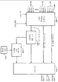
도 5A 는 본 발명의 오디오 누화 소거 망을 갖는 공간 화기의 일형태를 보여주는 기능블록도이다. 돌비 디지털 AC-3 시스템에서 처럼 5개의 오디오 입력 신호, 즉 좌측, 중앙, 우측, 좌측 서라운드 및 우측 서라운드 신호들이 수신된다. 그 신호들은 선택적인 DC 차단필터 (502,504,506,508,510)에 각각 인가된다. 좌측, 중앙 및 우측 입력 라인에서의 선택적 지연기들(512,514,516)은 누화 소거 망(520)에서의 지연시간에 대응하는 지연시간을 갖는다. 예를 들어, 누화 소거 망(520)이 증폭 압축기/제한기를 포함하지 않는다면 누화 소거 망(520) 및 지연기들(512,514,516)에서 시간 지연은 보통 존재하지 않는다. 이 예에서 누화 소거 망(520)에 대한 입력은 좌측 서라운드 및 우측 서라운드 입력이다. 누화 소거 망(520)의 간단한 실시예가 도5C 에 도시되어 있다. 도 5A를 다시 참조해 보면, 제1 선형 적응형 합산기(522)가 지연된 좌측 채널오디오 스트림을 수신한다. 제2 선형 적응형 합산기(524)가 지연된 우측 채널오디오 스트림을 수신한다. 지연된 중앙 채널 오디오 스트림이 상기 제1 및 제2 선형 적응형 합산기(522,524)에 인가된다. 누화 소거 망(520)으로부터 처리된 좌측 서라운드 채널 오디오 스트림이 또한 상기 제1 선형 적응형 합산기(522)에 인가된다. 누화 소거 망(520)으로부터 처리된 우측 서라운드 채널 오디오 스트림이 상기 제2 선형 적응형 합산기(524)에 또한 인가된다. 좌측 및 우측 서라운드 채널 오디오 스트림 만이 누화 소거 망에 의해 처리된다. 좌측 및 우측 전방 채널들이 누화 소거 망에 의해 처리된 좌측 및 우측 서라운드 채널들에 각각 부가된다. 중앙 채널은 부가적 처리없이 좌측 및 우측 출력으로 동위상 관계로 부가된다.5A is a functional block diagram showing one form of a spatializer with an audio crosstalk cancellation network of the present invention. As in the Dolby Digital AC-3 system, five audio input signals are received: left, center, right, left surround and right surround signals. The signals are applied to optional
돌비 서라운드 또는 돌비 서라운드 프로그래밍 논리 디코더에 의해 제공되는 바와 같은 4개의 입력신호들(좌측, 중앙 및 우측 채널 및 단일 서라운드 채널)이 존재할 경우 도5A의 구성이 또한 사용될 수 있다. 이 경우 단일 서라운드 채널은 2개의 의사 입체 음향 신호들로 분리 되는데, 이 신호들은 또한 소거기의 입력으로 인가된다. 하나의 신호가 다른 신호와 위상이 상이하도록 위상 시프트를 이용하여 간단한 변환기술이 사용될 수도 있다.The configuration of FIG. 5A can also be used when there are four input signals (left, center and right channel and single surround channel) as provided by the Dolby Surround or Dolby Surround programming logic decoder. In this case a single surround channel is split into two pseudo stereo signals, which are also applied to the input of the canceller. A simple conversion technique may be used using phase shift so that one signal is out of phase with another signal.
도 5B는 도 5A의 공간화기의 대안 구성을 보여준다. 도 5B에서 좌측 및 우측 전방 채널들은 부분 역위상 혼합기(526)에서의 부분 역위상 혼합에 의해 다소 확장된다. 스테레오 "스테이지"를 확장하기 위한 역위상 혼합기술은 공지된 바와 같다. 또 다른 선택구성으로서, 각 귀에 의해 두 번 들리는, 즉 한번은 가까운 음향 변환기로부터 그리고 다시 한번은 먼 음향 변환기로부터 들리는 중앙 신호에 따른 중복성을 최소화하기 위해 중앙 채널이 소거될 수 있다. 별도의 소거기를 구현하는 것보다는, 중앙 채널 음향 누화 신호들을 서라운드 채널 누화 소거 망에 인가함으로써 그 신호들을 소거할 수 있다. 따라서, 중앙 채널 신호는 선형 적응형 합산기들(527,528)을 각각 통하여 누화 소거 망(520)에 대한 좌측 서라운드 및 우측 서라운드 입력들로 혼합된다.5B shows an alternative configuration of the spatializer of FIG. 5A. In FIG. 5B the left and right front channels are somewhat expanded by partial antiphase mixing in partial
도 5C 는 도 5A 또는 5B 의 구성에서 사용가능한 간단한 음향 누화 소거기의 기본 요소들을 보여주는 기능블록도이다. 다른 보다 복잡한 소거기들이 사용될 수 있다. 각 지연기(530,532)는 도 1의 컴퓨터 모니터 환경 및 도 2의 텔레비전 환경에 대한 전형적인 각도인 +/-15°의 각도로 청취자에 대해 음향 변환기가 전방으로 배치되는 경우 약 140 ㎲(마이크로초)의 시간 지연을 갖는다. 각 필터(534,536)는 통상 약 0.9인 주파수와 무관한 감쇠팩터 K를 갖는다. 상술된 바와 같이 이 전의 각 소거기 신호의 소거를 위해 교차채널 부궤환 구성에서의 적응형 합산기(542,544)의 출력으로부터 각 누화 레그(538,540)의 입력이 발생된다(각 레그는 각 합산기에서 감산된다). 이러한 소거기는 지연기들에 대한 2개의 합산기, 2개의 승산기 및 한쌍의 6-샘플 링버퍼들을 디지털 방식으로 구현하기 위한 매우 간단한 음향 누화 소거기이다. 사용될 경우 상기 음향 누화 소거기는 소프트웨어 디지털 방식으로 구현되어 도 3의 모니터(306)와 관련된 개인용 컴퓨터 또는 도 4의 텔레비전(406)의 마이크로프로세서에서 실시간으로 동작하는 것이 바람직하다. FIG. 5C is a functional block diagram illustrating the basic elements of a simple acoustic crosstalk canceller usable in the configuration of FIG. 5A or 5B. Other more complex erasers can be used. Each
본 발명에 따르면, 인코더는 재생될 음장을 나타내는 복합 오디오-정보신호 및 방향벡터, 즉 "스티어링 제어신호"를 생성한다. 상기 복합 오디오-정보신호는 사람의 귀의 임계대역에 대응하는 다수의 부 대역으로 분리되는 주파수 스펙트럼을 갖는다. 상기 스티어링 제어신호는 각 부 대역에서 음장의 주 방향과 관련된 성분을 갖고 있다.According to the present invention, the encoder generates a composite audio-information signal and a direction vector representing the sound field to be reproduced, namely a "steering control signal". The composite audio-information signal has a frequency spectrum separated into a plurality of subbands corresponding to the critical band of the human ear. The steering control signal has a component related to the main direction of the sound field in each subband.
본 발명이 아날로그 또는 디지털 기술 또는 아날로그 및 디지털 혼합 기술을 이용하여 구현될 수 있지만, 본 발명은 디지털 기술을 이용하여 보다 편리하게 구현될 수 있으며 본 명세서에 설명된 바람직한 실시예들은 디지털 구현 방식이다. Although the present invention can be implemented using analog or digital technology or analog and digital mixing technology, the present invention can be implemented more conveniently using digital technology and the preferred embodiments described herein are digital implementations.
본 발명의 일 실시예에서는, 인코더는 입력채널 및 입력채널 각각의 위치설정 특성을 각각 나타내는 다수의 오디오 스트림을 수신한다. 디코더는 각 출력 채널에 대한 음향 변환기의 위치 또는 가상 위치 뿐만 아니라 인코딩 된 신호를 수신하며, 입력 채널 신호들로 표현되는 음장을 가능한 한 정확히 재생하기 위해 각 출력 채널에 대한 신호 스트림을 제공한다. 본 발명의 공간 코딩 구조가 단일 방향에서의 음향만을 항상 들을 수 있다는 전제에 기초를 두기 때문에, 상기 디코더는 2개의 음향 변환기에만 신호를 항상 인가해야 한다. 인코딩 된 정보는 각 부 대역에서 입력채널 모두에 대한 집합적 표현정보를 포함한다. 상기 표현정보는 순수한 전체 음장 레벨을 나타내는 복합 오디오-정보신호와 음장에 대한 위치설정 정보를 갖는 스티어링 제어신호를 포함한다. 상기 위치 설정 정보를 이하 순(net)방향 벡터라 언급한다.In one embodiment of the invention, the encoder receives a plurality of audio streams each representing an input channel and a positioning characteristic of each of the input channels. The decoder receives the encoded signal as well as the position or virtual position of the acoustic transducer for each output channel and provides a signal stream for each output channel to reproduce the sound field represented by the input channel signals as accurately as possible. Since the spatial coding structure of the present invention is based on the premise that only sound in a single direction can always be heard, the decoder must always apply a signal to only two sound transducers. The encoded information includes collective representation information for all input channels in each subband. The representation information includes a composite audio-information signal representing a pure overall sound field level and a steering control signal having positioning information for the sound field. This positioning information is referred to hereinafter as a net direction vector.
디코더에서는, 하나의 방향으로만 비트들을 취하는 경우 각 임계대역에서 하나 또는 두 개의 표현 채널들이 각 기간중에 비트들을 취한다(음장 방향이 표현채널 방향과 일치할 때 하나의 표현 채널이 적당하며, 일치하지 않으면 2개의 표현 채널들이 음장 방향을 설정하는데 필요하다). In the decoder, one or two presentation channels in each critical band take bits during each period when taking bits in only one direction (one presentation channel is suitable and the same when the sound field direction matches the presentation channel direction). Otherwise two presentation channels are needed to set the sound field direction).
본 발명의 일면에 따르면, 음장을 나타내는 다수의 오디오 스트림을 인코딩하고 그 인코딩된 신호를 디코딩하며 인코더 및 디코더를 구비하는 저 비트속도 공간 코딩 시스템이 제공된다.According to one aspect of the present invention, a low bit rate spatial coding system is provided that encodes a plurality of audio streams representing a sound field, decodes the encoded signal, and comprises an encoder and a decoder.
상기 인코더는 상기 다수의 오디오 스트림 각각의 주파수 부 대역을 각각 나타내는 다수의 부 대역 신호를 상기 다수의 오디오 스트림에 따라 발생시키는 부 대역 신호발생기와,The encoder may include: a subband signal generator for generating a plurality of subband signals representing frequency subbands of each of the plurality of audio streams according to the plurality of audio streams;
각 주파수 부 대역에서의 부 대역 신호들의 조합을 나타내는 복합 오디오 정보 신호를 발생시키는 복합 신호 발생기와,A composite signal generator for generating a composite audio information signal representing a combination of subband signals in each frequency subband;
각 부 대역에서 상기 음장의 주 방향을 나타내는 상기 복합 오디오 정보 신호에 대한 스티어링 제어신호를 발생시키는 주 방향 신호 발생기와,A main direction signal generator for generating a steering control signal for the composite audio information signal indicative of the main direction of the sound field in each subband;
상기 복합 오디오 정보 신호 및 스티어링 제어신호에 비트들을 할당함으로써 인코딩된 정보를 발생시키는 인코더 및 비트할당기와,An encoder and bit allocator for generating encoded information by allocating bits to the composite audio information signal and steering control signal;
상기 인코딩된 정보를 인코딩된 신호로 조합하는 포맷터를 포함한다.And a formatter for combining the encoded information into an encoded signal.
상기 디코더는 상기 인코딩된 신호로부터 복합 오디오 정보 신호 및 스티어링 제어신호를 추출하는 디포맷터와,The decoder includes a deformatter for extracting a composite audio information signal and a steering control signal from the encoded signal;
상기 복합 오디오 정보 신호 및 스티어링 제어신호에 따라 부 대역 신호를 추출하는 역 필터 뱅크와,An inverse filter bank for extracting a subband signal according to the complex audio information signal and a steering control signal;
3개 이상인 출력채널들의 수 및 각 출력채널들에 접속된 음향변환기들의 위치 또는 가상위치를 나타내는 재생정보를 공급하는 정보 입력부와,An information input unit for supplying reproduction information indicating the number of three or more output channels and the position or virtual position of the acoustic transducers connected to the respective output channels;
상기 부 대역 신호 및 재생정보에 따라 2개의 출력채널들에서만 오디오 스트림을 항상 발생시키는 신호 발생기를 포함한다.And a signal generator which always generates an audio stream only in two output channels according to the subband signal and reproduction information.
본 발명의 다른 면에 따르면, 음장을 나타내는 다수의 오디오 스트림을 인코딩하고 그 인코딩된 신호를 디코딩하며 상기 음장과 유사한 청각적 느낌을 재생하고 인코더 및 디코더를 구비하는 저 비트속도 공간 코딩 시스템이 제공된다.According to another aspect of the present invention, there is provided a low bit rate spatial coding system that encodes a plurality of audio streams representing a sound field, decodes the encoded signal, reproduces an auditory feel similar to the sound field, and comprises an encoder and a decoder. .
상기 인코더는 상기 다수의 오디오 스트림 각각의 주파수 부 대역을 각각 나타내는 다수의 부 대역 신호를 상기 다수의 오디오 스트림에 따라 발생시키는 부 대역 신호발생기와,The encoder may include: a subband signal generator for generating a plurality of subband signals representing frequency subbands of each of the plurality of audio streams according to the plurality of audio streams;
각 주파수 부 대역에서의 부 대역 신호들의 조합을 나타내는 복합 오디오 정보 신호를 발생시키는 복합 신호 발생기와,A composite signal generator for generating a composite audio information signal representing a combination of subband signals in each frequency subband;
각 부 대역에서 상기 음장의 주 방향을 나타내는 상기 복합 오디오 정보 신호에 대한 스티어링 제어신호를 발생시키는 주 방향 신호 발생기와,A main direction signal generator for generating a steering control signal for the composite audio information signal indicative of the main direction of the sound field in each subband;
상기 복합 오디오 정보 신호 및 스티어링 제어신호에 비트들을 할당함으로써 인코딩된 정보를 발생시키는 인코더 및 비트할당기와,An encoder and bit allocator for generating encoded information by allocating bits to the composite audio information signal and steering control signal;
상기 인코딩된 정보를 인코딩된 신호로 조합하는 포맷터를 포함한다.And a formatter for combining the encoded information into an encoded signal.
상기 디코더는 상기 인코딩된 신호로부터 복합 오디오 정보 신호 및 스티어링 제어신호를 추출하는 디포맷터와,The decoder includes a deformatter for extracting a composite audio information signal and a steering control signal from the encoded signal;
상기 복합 오디오 정보 신호 및 스티어링 제어신호에 따라 부 대역 신호를 추출하는 역 필터 뱅크와,An inverse filter bank for extracting a subband signal according to the complex audio information signal and a steering control signal;
출력채널들의 수 및 각 출력채널들에 접속된 음향변환기들의 위치 또는 가상위치를 나타내는 재생정보를 공급하는 정보 입력부와,An information input unit for supplying reproduction information indicating the number of output channels and the position or virtual position of the sound transducers connected to the respective output channels;
상기 부 대역 신호 및 재생정보에 따라 하나이상의 출력채널들에서 오디오 스트림을 발생시키는 신호 발생기를 포함한다.And a signal generator for generating an audio stream on one or more output channels in accordance with the subband signal and reproduction information.
상기 시스템은 상기 디코더의 출력채널들에 결합되며, 적당한 공간 코딩 청취영역에서 청취자 또는 청취자들에게 상기 음장과 유사한 청각적 느낌을 발생시키는 다수의 음향변환기를 추가로 구비한다.The system is further equipped with a plurality of acoustic transducers coupled to the output channels of the decoder and for generating a sound feeling similar to the sound field to the listener or listeners in a suitable spatial coding listening area.
본 발명의 또 다른 면에 따르면, 음장을 나타내는 다수의 오디오 스트림 각각의 주파수 부 대역을 각각 나타내는 다수의 부 대역 신호를 상기 다수의 오디오 스트림에 따라 발생시키고, 각 주파수 부 대역에서의 부 대역 신호들의 조합을 나타내는 복합 오디오 정보 신호를 발생시키며, 각 부 대역에서 상기 음장의 주 방향을 나타내는 상기 복합 오디오 정보 신호에 대한 스티어링 제어신호를 발생시키고, 상기 복합 오디오 정보 신호 및 스티어링 제어신호에 비트들을 할당하는 것에 의해 인코딩된 정보를 발생시키며, 상기 인코딩된 정보를 인코딩된 신호로 조합함으로써, 상기 다수의 오디오 스트림으로부터 추출된 인코딩된 신호를 디코딩하는 저 비트속도 공간 코딩 시스템용의 디코더가 제공된다.According to another aspect of the present invention, a plurality of subband signals each representing a frequency subband of each of a plurality of audio streams representing a sound field are generated according to the plurality of audio streams, and Generating a composite audio information signal indicative of the combination, generating a steering control signal for the composite audio information signal indicative of the main direction of the sound field in each subband, and allocating bits to the composite audio information signal and the steering control signal; Thereby generating encoded information and combining the encoded information into an encoded signal, thereby providing a decoder for a low bit rate spatial coding system for decoding the encoded signals extracted from the plurality of audio streams.
상기 디코더는 상기 인코딩된 신호로부터 복합 오디오 정보 신호 및 스티어링 제어신호를 추출하는 디포맷터와,The decoder includes a deformatter for extracting a composite audio information signal and a steering control signal from the encoded signal;
상기 복합 오디오 정보 신호 및 스티어링 제어신호에 따라 부 대역 신호를 추출하는 역 필터 뱅크와,An inverse filter bank for extracting a subband signal according to the complex audio information signal and a steering control signal;
3개 이상인 출력채널들의 수 및 각 출력채널들에 접속된 음향변환기들의 위치 또는 가상위치를 나타내는 재생정보를 공급하는 정보 입력부와,An information input unit for supplying reproduction information indicating the number of three or more output channels and the position or virtual position of the acoustic transducers connected to the respective output channels;
상기 부 대역 신호 및 재생정보에 따라 2개의 출력채널들에서만 오디오 스트림을 항상 발생시키는 신호 발생기를 구비한다.And a signal generator which always generates an audio stream only in two output channels according to the subband signal and reproduction information.
본 발명의 그 밖의 다른 면에 따르면, 음장을 나타내는 다수의 오디오 스트림 각각의 주파수 부 대역을 각각 나타내는 다수의 부 대역 신호를 상기 다수의 오디오 스트림에 따라 발생시키고, 각 주파수 부 대역에서의 부 대역 신호들의 조합을 나타내는 복합 오디오 정보 신호를 발생시키며, 각 부 대역에서 상기 음장의 주 방향을 나타내는 상기 복합 오디오 정보 신호에 대한 스티어링 제어신호를 발생시키고, 상기 복합 오디오 저오 신호 및 스티어링 제어신호에 비트들을 할당하는 것에 의해 인코딩된 정보를 발생시키며, 상기 인코딩된 정보를 인코딩된 신호로 조합함으로써, 상기 다수의 오디오 스트림으로부터 추출된 인코딩된 신호를 디코딩 및 재생하는 저 비트속도 공간 코딩 시스템용의 디코더 및 재생시스템이 제공된다.According to another aspect of the present invention, a plurality of subband signals each representing a frequency subband of each of a plurality of audio streams representing a sound field is generated according to the plurality of audio streams, and the subband signals in each frequency subband are generated. Generate a composite audio information signal indicative of a combination of the two components; generate a steering control signal for the composite audio information signal indicative of the main direction of the sound field in each subband, and assign bits to the composite audio low signal and the steering control signal; A decoder and playback system for a low bit rate spatial coding system that generates encoded information and combines the encoded information into an encoded signal to decode and reproduce encoded signals extracted from the plurality of audio streams. This is provided.
상기 디코더 및 재생 시스템은 상기 인코딩된 신호로부터 복합 오디오 정보 신호 및 스티어링 제어신호를 추출하는 디포맷터와,The decoder and playback system includes a deformatter for extracting a composite audio information signal and a steering control signal from the encoded signal;
상기 복합 오디오 정보 신호 및 스티어링 제어신호에 따라 부 대역 신호를 추출하는 역 필터 뱅크와,An inverse filter bank for extracting a subband signal according to the complex audio information signal and a steering control signal;
상기 디코더의 출력채널들의 수 및 각 출력채널들에 접속된 음향변환기들의 위치 또는 가상위치를 나타내는 재생정보를 공급하는 정보 입력부와,An information input unit for supplying reproduction information indicating the number of output channels of the decoder and the position or virtual position of the sound transducers connected to the respective output channels;
상기 부 대역 신호 및 재생정보에 따라 하나이상의 출력채널들에서 오디오 스트림을 발생시키는 신호 발생기와,A signal generator for generating an audio stream in one or more output channels according to the subband signal and reproduction information;
상기 디코더의 출력채널들에 결합되며, 적당한 공간 코딩 청취영역에서 청취자 또는 청취자들에게 상기 음장과 유사한 청각적 느낌을 발생시키는 다수의 음향변환기를 구비한다.Coupled to the output channels of the decoder, the decoder comprises a plurality of acoustic transducers that produce audible feeling similar to the sound field to the listener or listeners in a suitable spatial coding listening area.
이하 본 발명의 바람직한 실시예를 첨부한 도면을 참조하여 설명하겠다.Hereinafter, exemplary embodiments of the present invention will be described with reference to the accompanying drawings.
도1은 청취자가 다중표현채널에 의해 생성된 음장을 청취하지만 음향이 지점으로부터 발생하는 것을 인식하는 상태를 도시한 개념도.1 is a conceptual diagram illustrating a state in which a listener listens to a sound field generated by a multi-expression channel but recognizes that sound is generated from a point;
도2는 청취자가 5개의 음향 변환기 "서라운드 음향" 재생 구성에서 이상적인 공간코딩 스위트 스폿에 위치한 상태를 개략적으로 도시한 평면도.FIG. 2 is a plan view schematically showing a state where a listener is located in an ideal space coding sweet spot in a five acoustic transducer “surround sound” reproduction configuration; FIG.
도3은 청취자가 음향 변환기가 양측에 위치한 컴퓨터 모니터의 전방에 설정되는 이상적인 공간코딩 스위트 스폿에 위치한 상태를 개략적으로 도시한 평면도.Figure 3 is a plan view schematically showing a state where a listener is located in an ideal space coding sweet spot in which an acoustic transducer is set in front of a computer monitor on both sides;
도4는 음향 변환기가 브라운관 근처에 위치한 텔레비전의 전방에 설정되는 이상적인 공간코딩 스위트 스폿에 위치한 상태를 개략적으로 도시한 평면도.4 is a plan view schematically showing a state where an acoustic transducer is located in an ideal space coding sweet spot set in front of a television located near a CRT.
도5A는 음향 누화 소거기를 이용한 공간화기의 기능블록도.5A is a functional block diagram of a spatializer using an acoustic crosstalk canceller;
도5B는 음향 누화 소거기를 이용한 공간화기의 변형된 형태의 기능블록도.5B is a functional block diagram of a modified form of a spatializer using an acoustic crosstalk canceller;
도5C는 종래의 간단한 4-포트 음향 누화 소거기의 기능블록도.Fig. 5C is a functional block diagram of a conventional simple four-port acoustic crosstalk canceller.
도6은 공간 코딩 및 디코딩 방법을 보여주는 개념 블록도.6 is a conceptual block diagram illustrating a spatial coding and decoding method.
도7은 부 대역 인코더의 기본 구조를 도시한 기능블록도.7 is a functional block diagram showing the basic structure of a subband encoder.
도8은 부 대역 디코더의 기본 구조를 도시한 기능블록도.8 is a functional block diagram showing the basic structure of a subband decoder.
도9는 부 대역 인코딩과 관련된 본 발명의 기본 구조를 도시한 기능블록도.9 is a functional block diagram illustrating the basic structure of the present invention related to subband encoding.
도10은 부 대역 디코딩과 관련된 본 발명의 기본 구조를 도시한 기능블록도.Fig. 10 is a functional block diagram showing the basic structure of the present invention related to subband decoding.
도11은 재생 시스템을 5개의 표현채널을 갖는 3차원 형태로 도시한 가상 그래픽 표현도.FIG. 11 is a virtual graphical representation showing a playback system in three dimensional form with five representation channels; FIG.
도12A는 예측가능 재생 환경과 관련하여 동작하는 공간디코더의 개략적 기능 블록도.12A is a schematic functional block diagram of a spatial decoder operating in conjunction with a predictable playback environment.
도12B는 또 다른 예측가능 재생 환경과 관련하여 동작하는 공간디코더의 개략적 기능 블록도.12B is a schematic functional block diagram of a spatial decoder operating in conjunction with another predictable playback environment.
도 6은 유형 II 코딩 시스템의 실시예를 도시한 개념도이다. 처리부(604,606)들을 구비하는 인코더는 부 대역 코더(도7참조)로 부터의 다수의 입력채널들(602)로부터 음장을 나타내는 부 대역 신호를 수신하고, 상기 입력 채널들 각각으로 음장이 매핑되는 방법에 관한 정보를 경로(603)로부터 수신한다. 상기 처리부(604)는 상기 신호들을 경로(608)를 따라 전송되는 복합 오디오-정보 신호로 조합한다. 상기 처리부(606)는 음장의 주 방향을 나타내는 스티어링 제어신호를 발생시키며, 이 제어신호는 경로(610)를 따라 전송된다. 처리부(612)를 구비하는 디코더는 출력 채널들의 수 및 표현시스템에서의 출력채널 음향 변환기들의 실제 또는 가상 공간 구성에 관한 정보를 경로(613)로부터 수신하고, 복합채널 신호를 경로(608,610)부터 수신하며, 음장의 표현을 위해 출력들(614)에 따라 출력신호를 발생시킨다. 6 is a conceptual diagram illustrating an embodiment of a type II coding system. An encoder having
상기 공간 디코더를 실제로 응용하면, 입력채널들을 나타내는 다수의 신호 스트림들이 인코더에 대한 정보가 된다. 상기 인코더는 소정의 재생 음장과 관련되며, 따라서 상기 입력 채널들이 상기 음장과 관련되는 방법에 관한 정보를 수신해야 한다. 예를 들어, 5-채널소스가 표준화된 음향 변환기 위치에 따른 좌측, 중앙, 우측, 좌측 서라운드 및 우측 서라운드 재생 구성을 갖는 경우, 그러한 음향 변환기 위치에 인가될 5개의 채널 신호로부터 순 방향 벡터가 추출될 수 있다. When the spatial decoder is actually applied, a plurality of signal streams representing input channels become information about an encoder. The encoder is associated with a predetermined reproduction sound field, and therefore must receive information regarding how the input channels are associated with the sound field. For example, if a 5-channel source has left, center, right, left surround and right surround playback configurations according to standardized sound transducer positions, a forward vector is extracted from the five channel signals to be applied to such sound transducer positions. Can be.
재생 또는 표현환경에 관한 정보를 수신하는 공간 코딩 디코더는 상기 제한된 5-채널 재생 또는 표현환경을 위한 또는 상이한 개수의 채널들 및/또는 음향 변환기 위치를 이용한 또 다른 재생 또는 환경을 위한 신호집합을 발생시키기 위해 상기 순 방향 벡터를 이용할 수 있다. 예를 들어, 2-음향 변환기 컴퓨터 모니터 환경을 위해 상기 복합 오디오-정보신호 및 순 방향 벡터가 디코딩 될 수 있다. 상술된 바와 같이, 상기 디코더는 2개의 음향 변환기 및 그들 간의 간격에 제한되지 않는 음장의 음향심리학적 효과가 결과적으로 표현될 수 있도록 "공간화기"를 포함할 수 있다. A spatial coding decoder that receives information about a playback or presentation environment generates a signal set for the limited five-channel playback or presentation environment or for another playback or environment using a different number of channels and / or sound transducer locations. The forward vector can be used for this purpose. For example, the complex audio-information signal and the forward vector may be decoded for a two-sound converter computer monitor environment. As described above, the decoder may include a "spatializer" such that the psychoacoustic effects of the sound field, which are not limited to the two acoustic transducers and the gap therebetween, can be represented as a result.
본 발명은 다중입력 채널을 발생시키는 어느 구조나 음장을 포착 또는 재현하는 어느 구조에서도 사용될 수 있다. 본 발명에 따르면, 인코더의 입력으로서, 발생기가 음장을 발생시키기 위해 입력 채널들을 발생시키는 방법을 정의하는데 필요한 정보, 즉 청취자에 대한 소정 방향에 관한 정보를 갖는 다중 입력 채널들의 어느 집합도 사용될 수 있다. 상기 인코더는 상기 정보 및 음향 채널들을 복합 오디오 정보 신호 및 순 방향 벡터 스티어링 제어신호로 변환하여 상기 디코더가 재 생 또는 표현 장치 및 환경의 능력에 가장 바람직하게 대응하는 음장을 생성하는 표현 채널 집합을 출력할 수 있도록 한다. 상기 디코더에 의해 발생된 채널 수는 표현 시스템의 특성에 따라 결정되며 따라서 입력 채널들의 수와 반드시 일치할 필요는 없다.The present invention can be used in any structure that generates multiple input channels or any structure that captures or reproduces sound fields. According to the invention, as the input of the encoder, any set of multiple input channels with information necessary for defining how the generator generates the input channels to generate a sound field, i.e. information about a given direction to the listener, can be used. . The encoder converts the information and acoustic channels into a composite audio information signal and a forward vector steering control signal to output a set of representation channels for which the decoder generates a sound field most preferably corresponding to the capabilities of the playback or representation apparatus and the environment. Do it. The number of channels generated by the decoder is determined according to the characteristics of the presentation system and therefore does not necessarily match the number of input channels.
본 발명은 어느 공지된 기술에 따라서든 구현된 부 대역 코더에 적용 가능하다. 바람직한 구현 기술은 변환기술인데, 특히 시간 영역 에일리어싱 소거(TDAC)기술에 따른 시간 영역/주파수 영역 변환기술이다. 이러한 변환기술은 Princen 및 Bradley 에 의한 논문("Analysis/Synthesis Filter Bank Design Based on Time Domain Aliasing Cancellation," IEEE Trans. on Acoust.,Speech, Signal Proc., vol. ASSP-34, 1986, pp. 1153-1161)에서 볼 수 있다. TDAC 변환을 이용한 변환 인코더/디코더 시스템의 일 예가, 본 명세서에 있는 그대로 참조를 위해 포함된 미합중국 특허 제 5,109,528 호에 기재되어 있다. The invention is applicable to subband coders implemented according to any known technique. A preferred implementation technique is the conversion technique, in particular the time domain / frequency domain transformation technique according to the time domain aliasing cancellation (TDAC) technique. This conversion technique is described by Princen and Bradley ("Analysis / Synthesis Filter Bank Design Based on Time Domain Aliasing Cancellation," IEEE Trans.on Acoust., Speech, Signal Proc., Vol. ASSP-34, 1986, pp. 1153 -1161). An example of a transform encoder / decoder system using a TDAC transform is described in US Pat. No. 5,109,528, which is incorporated by reference as is herein.
도 7에 도시된 바와 같이, 전형적인 단일 채널 부 대역 인코딩 방법은 입력 신호 스트림을 필터 뱅크(710)를 이용하여 부 대역들로 분리하는 단계와, 그 부 대역 정보를 인코더(730)를 이용하여 양자화 코드 워드로 변환하는 단계와, 그 양자화 코드 워드를 포맷터(740)를 이용하여 전송 또는 저장에 적합한 형태로 조합하는 단계로 이루어진다. 상기 필터 뱅크가 디지털 필터 또는 이산 변환기로 구현되면, 그 입력 신호는 필터 뱅크 필터링 이전에 샘플러(700)에 의해 샘플링 되어 디지털화된다. 상기 필터가 아날로그 필터로 구현되는 경우, 부 대역 신호들이 인코더(730)에 의한 디지털 코딩을 위해 샘플러(720)에 의해 샘플링 되어 디지털화된다. 일 특성에 따르면, 본 발명은 정보의 다중채널을 위한 인코더(730)에 관한 것이다. 예를 들어 도 6에서의 각 입력(602)은 인코더(730)에 인가되는 부 대역 정보를 형성한다. As shown in FIG. 7, a typical single channel subband encoding method includes separating an input signal stream into subbands using a
도 8에 도시된 바와 같이, 전형적인 단일 채널 부 대역 디코딩 방법은 포맷팅된 코드워드를 디포맷터(810)를 이용하여 분해하는 단계와, 디코더(820)를 이용하여 부 대역 정보를 복원하는 단계와, 이 부 대역 정보를 역 필터 뱅크(840)를 이용하여 단일 채널 신호로 조합하는 단계로 이루어진다. 상기 역 방향 필터 뱅크가 아날로그 필터로 구현되고 신호가 디지털방식으로 인코딩 되면, 부 대역 정보는 역 필터 뱅크 필터링이전에 변환기(830)에 의해 아날로그 형태로 변환된다. 상기 역 필터 뱅크가 디지털 필터 또는 이산 변환기로 구현되는 경우, 디지털 신호는 변환기(850)에 의해 아날로그 형태로 변환된다. 또 다른 특성에 따르면 본 발명은 정보의 다중 채널을 위한 디코더(820)에 관한 것이다.As shown in FIG. 8, a typical single channel subband decoding method includes decomposing a formatted codeword using a
부 대역 스티어링에 따라 하나 이상의 채널들로부터의 부 대역 성분이 복합 오디오 정보 신호로 조합된다. 부 대역에 대한 복합표현이 복합채널 부 대역에 의해 표현된 개별적인 채널 부 대역 스펙트럼 성분 대신에 전송되어 기록된다. 복합 채널을 형성하는 2 가지 방법이 있으며 동일한 결과를 얻는다. 제 1 방법은, 먼저 마스킹 된 신호 성분의 코딩을 배제함으로써 각 채널에 요구된 비트 수를 감소시키기 위해 각 채널에 대역 내 마스킹 기준을 적용하고, 이어서 복합 오디오 정보 신호를 생성하기 위해 비트 감소된 채널들을 합성한다. 제 2 방법은, 먼저 복합 오디오 정보 신호를 생성하기 위해 본래의 채널 신호들을 합성하고, 이어서 마스킹 된 신호성분의 코딩을 배제함으로써 비트 수를 감소시키기 위해 복합 오디오 정보 신호에 대역 내 마스킹 기준을 적용시키는 것이다. 그 결과적인 복합 오디오 정보 신호는 어느 방법이든 기본적으로 동일하다. 양 방법에서, 공간 코더는 결과적인 복합 채널 내에서 2 가지 형태의 마스킹을 고려하는데, 즉 교차 채널 마스킹 및 대역 내 마스킹을 고려한다. 따라서 본 발명은 복합 오디오 정보 신호를 형성하는 방법 모두의 사용을 허용한다.According to subband steering, subband components from one or more channels are combined into a composite audio information signal. The composite representation for the subband is transmitted and recorded instead of the individual channel subband spectral components represented by the composite channel subband. There are two ways to form a composite channel and get the same result. The first method applies an in-band masking criterion to each channel to reduce the number of bits required for each channel by first eliminating the coding of the masked signal components, and then a bit reduced channel to generate a composite audio information signal. Synthesize them. The second method involves first applying the in-band masking criteria to the composite audio information signal to reduce the number of bits by first synthesizing the original channel signals to produce the composite audio information signal and then excluding coding of the masked signal component. will be. The resulting composite audio information signal is basically the same in either way. In both methods, the spatial coder considers two types of masking within the resulting composite channel, namely cross channel masking and in-band masking. The present invention thus allows the use of both methods of forming a composite audio information signal.
스티어링 제어 신호(즉, 순 방향 벡터)는 모든 채널로부터 스펙트럼 성분의 주 방향을 나타낸다. 디지털 인코딩 기술에 대한 본 발명의 교시에 따르면, 스펙트럼 성분을 나타내는 숫자 값이 코드워드로 양자화 되는데, 가변적인 비트 수가 코드워드의 최소한 일 부분에 적응 적으로 비트 저장부로부터 할당될 수 있다. 이 비트할당은, 현재의 신호성분으로 인해, 어떤 부 대역에서의 양자화 오차가 다른 부 대역에서의 양자화 오차보다 크게 신호 코딩품질을 저하시키는 지의 여부에 따라 좌우된다.The steering control signal (ie, forward vector) represents the main direction of the spectral component from all channels. According to the present teachings of digital encoding techniques, numeric values representing spectral components are quantized into codewords, where a variable number of bits can be adaptively assigned from at least one portion of the codeword from the bit store. This bit allocation depends on whether the signal coding quality deteriorates more than the quantization error in one subband due to the current signal component.
특히, 양자화 잡음이 다른 부 대역에서의 양자화 잡음보다 음향심리학적 마스킹을 덜 받는 부 대역에서의 스펙트럼 성분들에 보다 많은 비트가 할당된다.In particular, more bits are allocated to spectral components in the subband where quantization noise is less psychoacoustically masked than quantization noise in other subbands.
디코딩에 대한 본 발명의 교시에 따르면, 역 스티어링에 따라 스티어링 제어신호가 복합채널로부터 스티어링된 채널들의 표현을 복원하기위해 사용된다. 본 발명에 따른 공간 코딩이 단일 방향 벡터를 이용하고 청취자가 일 방향의 음향만을 항상 듣는다는 기본적인 원리의 관점에서, 특정표현 시스템상의 표현을 위해 하나 또는 2개의 채널만이 발생되어야 한다. 디코더를 위한 채널들의 수는 표현 시스템의 특성에 따라 결정되며 따라서, 입력 채널들의 수와 반드시 일치할 필요는 없다. According to the teachings of the present invention for decoding, in accordance with inverse steering, a steering control signal is used to restore the representation of the steered channels from the composite channel. In view of the basic principle that the spatial coding according to the invention uses a single direction vector and the listener always hears only one direction of sound, only one or two channels must be generated for representation on a particular representation system. The number of channels for the decoder is determined according to the characteristics of the presentation system and therefore does not necessarily match the number of input channels.
또한 디지털 디코딩 기술에 대한 본 발명의 교시에 따르면, 양자화 된 각 코드워드에 할당된 비트 수를 발생시키기 위해, 인코딩 중에 사용된 처리와 유사한 적응 식 비트 할당 처리가 수행된다. 이 정보는 부 대역 스펙트럼 성분을 재현하는데 사용된다. 도 9는 공간 코딩 인코더(즉, 간단한 단일 벡터 유형 II 인코더)의 개략적인 기능 블록도 이다. 상기 인코더는 다양한 아날로그 및 디지털 코딩 기술을 이용하여 구현될 수 있다. 본 발명은 디지털 기술을 이용하여 보다 편리하게 구현될 수 있으며 본 명세서에서 설명된 실시예 들은 디지털 방식으로 구현된다.Also in accordance with the present teachings of the digital decoding technique, an adaptive bit allocation process similar to the process used during encoding is performed to generate the number of bits allocated to each quantized codeword. This information is used to reproduce the subband spectral components. 9 is a schematic functional block diagram of a spatial coded encoder (ie, a simple single vector type II encoder). The encoder can be implemented using various analog and digital coding techniques. The present invention can be implemented more conveniently using digital technology and the embodiments described herein are implemented digitally.
디지털 구현 방식은 적응식 비트 할당 기술을 이용할 수 있다. 바람직한 실시예의 설명이 적응식 비트 할당 개념 및 부 대역 스티어링 개념 둘 다를 포함하고 있지만, 적응식이 아닌 비트 할당 구조로 공간 코딩의 디지털 구현이 가능할 수 있다.Digital implementations can use adaptive bit allocation techniques. Although the description of the preferred embodiment includes both the adaptive bit allocation concept and the subband steering concept, it may be possible to digitally implement spatial coding with a non-adaptive bit allocation structure.
도 9를 참조해 보면, 주 방향 스티어링 제어 신호 및 복합 오디오 정보 신호를 형성하기 위해 입력 경로(901)상의 다수의 입력 채널들(1-N) 각각에 대한 부 대역 신호 성분들이 주 방향 및 복합 신호 발생기(902)에 의해 처리된다. 프로세스는 소스 음장이 각 입력 채널에 매핑되는 방법을 나타내는 소스 정보(각 채널 신호에 대해 의도된 공간 방향을 나타내는 정보)를 또한 수신한다. 상기 소스 및 재생 정보는 고정적이거나 프로그램 가능하다. 상기 인코더가 소스 및/또는 재생환경에 관한 고정 명령들을 포함하거나 상기 명령들이 도 9에 도시된 바와 같이 입력 경로를 통해 인코더 외부로부터 제공될 수 있다. 소스 음장을 나타내는 복합 오디오-정보 신호가 부 대역 입력 신호 및 소스 정보로부터 추출된다. 음장의 위치설정 정보를 포함하는 단일 방향 벡터 형태의 스티어링 제어신호가 부 대역 입력 신호 및 소스 정보로부터 추출된다.Referring to FIG. 9, the subband signal components for each of the plurality of input channels 1 -N on the
주 방향 및 복합 신호 발생기(902)의 복합 오디오 정보 신호 출력이 코스 레벨 양자화기(904)에 또한 인가되며, 상기 양화화기는 단일 복합 채널의 부 대역 스펙트럼 정보를 양자화한다. 적응형 비트 할당기(908)는 코스레벨 양자화기(904)로부터 수신된 코스 양자화 정보 및 비트 저장부(910)로부터 수신된 할당 가능한 비트 수에 따라 다수의 비트를 다양한 부 대역에 할당한다. 양자화기(912)는 복합 오디오 정보 신호, 코스레벨 양자화기의 출력 및 적응형 비트 할당기의 출력에 따라 복합 오디오 정보 신호 스펙트럼 정보를 양자화 코드워드로 적응방식으로 양자화한다. 적당한 알고리즘이 아래에 설명되지만, 인코더가 적응방식으로 비트를 할당하는 알고리즘은 본 발명에서는 중요한 사항은 아니다. 상기 양자화기(912)는 스티어링 제어신호를 또한 양자화 한다. 이 양자화기(912)는 경로들(914-918)을 각각 따라서 스티어링 정보, 양자화 코드워드 및 코스 양자화 정보를 출력으로서 제공한다.A composite audio information signal output of the main direction and the
도 10은 공간 코딩 디코더의 개략적인 기능 블록도이다. 적응형 비트할당 계산기(1002)는 인코더 출력(918)으로부터 수신된 코스 양자화 정보 및 비트 저장부(1004)로부터 수신된 할당 가능한 비트수에 따라 양자화 중에 각 코드워드에 할당될 비트 수를 설정한다. 역 양자화기(1006)는 인코더 출력(916)으로부터 수신된 양자화 코드워드, 인코더 출력(918)으로부터 수신된 코스 양자화 정보 및 적응형 비트 할당 계산기(1002)로부터 수신된 비트 할당 정보에 따라 인코더 출력(914)로부터 수신된 스티어링 제어신호를 역 양자화하여 스펙트럼 성분정보를 복원하고, 단일 방향 벡터 정보, 복합 채널 부 대역 지수성분 및 복합 채널 스펙트럼 성분을 경로들(1008,1010,1012)을 각각 따라서 출력한다. 이들 출력들은 역 주방향 및 복합신호 발생기(1014)에 인가되며, 이 발생기는 출력 채널들이 기대수 및 그 출력채널들에 접속된 음향 변환기들(스피커들)의 위치 또는 가상 위치를 나타내는 재생정보를 또한 수신한다. 상기 재생정보는 고정되거나 프로그램 가능하다. 상기 디코더가 재생환경에 관한 고정 명령들을 포함하거나 상기 명령들이 도 10에 도시된 바와 같이 입력 경로를 통해 디코더 외부로부터 제공될 수 있다. 역 주방향 및 복합 신호 발생기(1014)는 부 대역 신호 세트 및 방향벡터가 수신되는 각 기간 내에 경로들(1008-1012)상에서 수신된 스티어링 및 복합 스펙트럼 정보에 따라 부 대역들을 재현하며, 부 대역 스펙트럼 성분의 하나 또는 2개의 채널에 대해 완전한 부 대역 세트가 수신되고, 각 채널은 Ch 1,...,Ch N 으로 표기된 경로(1016)의 부분들로서 나타낸다. 상기 기간 중에 각 부 대역에 대한 하나 또는 2개의 채널의 활성화는 각 부 대역에서 단일 방향으로의 음향을 재생하기에 충분하다. 즉, 어느 부 대역에 대해서도 각 기간 중에 하나 또는 2개의 채널만이 할성화 된다.10 is a schematic functional block diagram of a spatial coding decoder. Adaptive
인코딩 및 디코딩 기술에 관한 본 발명의 바람직한 실시예가 이제 보다 상세히 설명되겠다. 본 발명은 대안 실시예 및 구성은 명세서 전반을 통해 제시된다. Preferred embodiments of the present invention relating to encoding and decoding techniques will now be described in more detail. Alternative embodiments and configurations are set forth throughout the specification.
유형 II 부 대역 인코더를 도시한 도 9를 재 참조해 보면, 주 방향 및 복합 신호 발생기(902)가 경로(901)를 따라 부 대역 정보의 다중 채널을 수신한다. 부 대역 블록들이 이산 푸리에 변환(DFT)과 같은 이산 변환에 의해 추출되는 경우 각 부 대역은 하나 이상의 이산 변환 계수로 구성된다. 20 kHz 대역 폭 신호에 대해 하나의 특정 부 대역을 구성하기 위해 512 포인트 변환 및 48 kHz 의 입력 신호 샘플링 속도가 사용된다. 상기 부 대역들은 일반적으로 인간의 귀의 임계대역에 대응한다. 다른 부 대역 그룹화, 샘플링 속도 및 변환길이가 본 발명의 범주로부터 벗어나지 않는 한 활용될 수 있다.Referring again to FIG. 9, which shows a type II subband encoder, the main direction and
상술된 바와 같이, 기간이 충분히 짧을 때 단일 방향 효과가 작용한다. 48kHz 샘플링 속도 및 512 포인트 변환의 경우, 각 변환 블록은 약 10 밀리초의 시간 간격을 갖는다(DTAC 변환의 경우, 상기 시간 간격은 DTAC 처리에서 블록간 평균 고유 값의 관점에서 대략적인 값이다). 따라서 약 10 밀리초마다 일련의 복합 부 대역 신호들이 발생한다. 각 복합 블록은 관련된 단일 방향 벡터를 가질 수 있으며, 이와는 달리 상기 블록 기간보다 많거나 적은 횟수로 방향 벡터들이 규칙적으로 발생 될 수 있다. 또 다른 대안 구성으로서, 한계 값(즉, 30°를 초과한 각도)보다 큰 주 방향에서의 시프트가 행해질 때만 하나 이상의 부가적인 방향 벡터가 블록 기간 내에 발생 될 수도 있다. 약 10 밀리초의 블록 길이 및 각 블록 기간 중의 단일 방향 벡터를 갖는 시스템에 따른 TDAC 변환에 따라 즐거운 음악이 재생될 수 있다.As mentioned above, the unidirectional effect acts when the period is sufficiently short. For a 48 kHz sampling rate and a 512 point transform, each transform block has a time interval of about 10 milliseconds (for a DTAC transform, the time interval is an approximate value in terms of average interblock average eigenvalues in DTAC processing). Thus, a series of complex subband signals occurs about every 10 milliseconds. Each complex block may have a single direction vector associated with it. Alternatively, direction vectors may be generated regularly more or less times than the block period. As another alternative arrangement, one or more additional direction vectors may be generated within the block period only when a shift in the main direction that is greater than the threshold value (ie an angle exceeding 30 °) is made. Pleasant music can be played according to the TDAC transform according to a system having a block length of about 10 milliseconds and a single direction vector during each block period.
주 방향 및 복합 신호 발생기는 다중 채널로부터의 스펙트럼 성분을 합성하여 복합 단일 채널 부 대역을 형성하며, 이에 의해 양자화 되고 전송되어야 하는 스펙트럼 성분들의 수가 감소된다. 소정의 기간 내에 음장의 주 방향(단일 방향)에 관한 정보를 전달하는 스티어링 제어 신호가 인코딩된 복합 채널 스펙트럼 성분과 함께 전송되기 때문에, 그들을 수신하는 역 양자화기가 단일 방향 재생을 위해 충분한 하나 또는 2개의 채널에 대한 스펙트럼 성분을 복원할 수 있다. 일반적으로 복합 채널 및 단일 방향 제어 신호로부터 복원된 스펙트럼 성분이 수신기가 이산 채널로부터 디코딩하거나 각 채널에 대한 복합 채널 및 스케일 팩터를 형성하는 스펙트럼 성분과는 동일하지 않다(유형 I 시스템 참조).The main direction and the composite signal generator synthesize spectral components from multiple channels to form a composite single channel subband, thereby reducing the number of spectral components that must be quantized and transmitted. Since steering control signals that convey information about the main direction (single direction) of the sound field within a predetermined period of time are transmitted with the encoded composite channel spectral components, one or two inverse quantizers receiving them are sufficient for unidirectional reproduction. It is possible to recover the spectral components for the channel. In general, the spectral components reconstructed from the composite channel and unidirectional control signal are not the same as the spectral components that the receiver decodes from the discrete channels or forms the composite channel and scale factor for each channel (see Type I system).
이산 채널의 부 대역 또는 복합 채널 부 대역 및 채널 스케일 벡터를 인코딩하는 것(유형 I 시스템 참조)보다 복합 채널 부 대역 및 부수적인 단일 방향 벡터를 인코딩 함으로써 절감된 비트 수가 적응형 비트 할당 처리에 의해 사용되어 다른 부 대역에 할당되거나 양자화기가 스티어링 제어신호를 양자화 할 수 있다.Reduced number of bits used by adaptive bit allocation processing by encoding the composite channel subband and the incidental unidirectional vector rather than encoding the subband or composite channel subband and channel scale vectors of the discrete channels (see Type I system). Can be allocated to other subbands or the quantizer can quantize the steering control signal.
하나 이상의 채널에서의 부 대역의 스펙트럼 성분들이 합성된다. 상기 5,583,962, 5,632,005, 5,633,981 특허에 따르면, 바람직한 방법은 복합 부 대역의 각 스펙트럼 성분 값을 스티어링된 채널들의 대응하는 스펙트럼 성분 값들의 평균값과 일치시키며, 다른 방법들은 다른 선형 조합 값들을 형성하거나 스티어링된 채널들의 스펙트럼 성분 값들의 가중치 합을 구할 수 있다.Subband spectral components in one or more channels are synthesized. According to the 5,583,962, 5,632,005, 5,633,981 patents, the preferred method matches each spectral component value of the composite subband with the average value of the corresponding spectral component values of the steered channels, while other methods form different linear combination values or steered channels. The weighted sum of the spectral component values can be obtained.
상기 스티어링 제어 신호는 복합 채널내의 부 대역 성분들의 일차(즉, 주)공간 방향을 나타낸다. 본 발명의 요지인 유형 II 시스템의 간략화 된 버전에 따르면, 각 기간 중에 기본적인 방법은 복합 오디오 정보 신호 내의 각 부 대역에 대한 일차 또는 주 공간 방향만을 나타내는 단일 벡터를 형성한다.The steering control signal represents the primary (ie, main) spatial direction of the subband components in the composite channel. According to a simplified version of the Type II system, which is the subject of the present invention, during each period the basic method forms a single vector representing only the primary or main spatial direction for each subband in the composite audio information signal.
5개의 표현채널을 갖는 가상 재생 시스템을 도시한 도 11도를 참조하면 상기 기본방법의 개념을 보다 잘 이해할 수 있겠다. 입력 채널들 중 하나에 대응하는 상기 표현 채널들 각각은 단위 영역의 표면상에 위치한 음향 변환기를 나타낸다. 청취자는 상기 영역의 중앙에 위치한다. 채널들 중 하나가 RF로 표기된다. 채널 RF의 청취자에 대한 주 방향이 단위 벡터 ![]()
![]()
이러한 기본 코딩 방법에 따르면, 스티어링 제어신호 벡타(![]()
![]()

여기서, ![]()
![]()
LIij = 채널 i에서의 부 대역 j에 대해 계산된 레벨 LI ij = calculated level for subband j on channel i
S = 입력 채널들의 전체 수 S = total number of input channels
![]()
![]()
![]()
![]()
![]()
![]()
본 발명에서 사용 가능한 유형 II 인코더의 추가의 상세한 설명은 상기 5,583,962, 5,632,005 및 5,633,981 특허에서 기재되어 있다.Further details of the type II encoders usable in the present invention are described in the above patents 5,583,962, 5,632,005 and 5,633,981.
도 10에 도시된 공간 코딩 디코더에서는, 역 주 방향 및 복합 신호 발생기(1014)는 경로들(1008-1012)로부터 각각 수신된 스티어링 제어신호, 코스 양자화 레벨 및 스펙트럼 성분 값들에 따라 복합 채널의 단일 방향 표현을 재현한다. In the spatial coding decoder shown in FIG. 10, the inverse main direction and the
상술된 바와 같이, 유형II 코딩 별명은 스티어링 제어신호의 방향 벡터형태를 이용한다. 인코딩된 신호의 방향을 근사화 시키기 위해, 재현 처리는 디코딩 측에 설치된 음향 변환기들이 수와 위치를 고려해야 한다. 역 주 방향 복합신호 발생기(1014)에 대한 재생정보 입력으로서 각 표현채널 i에 대한 방향 벡터![]()
![]()
상기 방정식 1을 표현시스템에 적용하면 스티어링 제어 신호는 다음과 같이 표현될 수 있다.Applying
![]()
![]()
여기서, ![]()
![]()
LIij = 채널 i에서의 부 대역 j에 대해 계산된 레벨LI ij = calculated level for subband j on channel i
S = 표현 채널들의 전체 수 S = total number of presentation channels
![]()
![]()
![]()
![]()
![]()
![]()
계산된 레벨 LO에 따라 부가된 하나의 추가조건은 표현 시스템에 의해 생성된 음장의 소리 레벨이 본래의 음장의 소리 레벨과 같아야 한다는 것이다. 특히 표현 시스템에 의해 생성된 각 부 대역의 음장의 소리 레벨이 본래의 음장의 부 대역 소리 레벨과 같도록 조건이 각 ![]()
![]()
본 발명에서 사용 가능한 유형 II 디코더의 추가의 상세한 설명은 상기 제 5,583,962호, 제 5,632,005호 및 제 5,633,981호 특허에서 기재되어 있다. Further details of the type II decoder usable in the present invention are described in the above-mentioned patents 5,583,962, 5,632,005 and 5,633,981.
도 12A는 예측 가능한 재생 환경과 관련하여 동작하는 공간 디코더의 개략적 기능 블록도이다. 스티어링 정보, 양자화 코드워드 및 코스 양자화 정보가 입력경로들(1202, 1204,1206)에 따라 공간 디코더(1208)에 각각 인가된다. 입력 신호들은 예를 들어 유무선 전송, 자기매체 및 광학 매체를 포함하는 다양한 전송 또는 저장 기술에 의해 공간 디코더로 전송될 수 있다. 상술된 바와 같이, 입력신호들은 유형 II 시스템의 단일 벡터 버전에 따라 인코딩 된다. 디코더(1208)는 음향 누화 소거기를 갖는 선택적 공간화기(1210)에 인가될 수 있는 4-5개의 출력신호들을 제공한다. 상기 공간화기(1210)의 특정 구성이 한정되지는 않지만 그와 관련된 적당한 구성들이 도5A, 5B, 5C와 관련하여 설명되어 있다. 사용되는 경우 공간화기(1210)는 좌측 및 우측 음향 변환기(1212,1214)에 인가되며(도시 생략된 적당한 증폭 및 결합수단을 통하여), 사용되지 않는 경우에는 디코더(1208)출력들이 적당한 증폭 및 결합수단(도시 생략)을 통해 상기 음향 변환기에 인가된다. 예를 들어 도3 또는 도4의 방식으로 배치된 음향 변환기는 청취자(1217)가 위치하는 장원형의 공간 코딩 스위트 스폿(1216)(이상적으로 도시됨)을 형성한다.12A is a schematic functional block diagram of a spatial decoder operating in conjunction with a predictable playback environment. Steering information, quantization codewords and coarse quantization information are applied to the
도12B는 또 다른 예측 가능 재생 환경과 관련하여 동작하는 공간 디코더의 개략적 기능 블록도이다. 스티어링 정보, 양자화 코드워드 및 코스 양자화 정보가도 12A에 도시된 바와 같이 입력경로들(1202, 1204, 1206)에 따라 공간 디코더(1208)에 각각 인가된다. 도 12B의 구성은 재생환경이 표준 5-음향 변환기 서라운드 음향 구성이라는 점에서 상이하다. 이 경우 공간화기는 필요 없다. 공간 디코더(1208)의 출력들이 5개의 음향 변환기들 즉, 좌측(1218), 중앙(1220), 우측(1222), 좌측 서라운드(1224) 및 우측 서라운드(1226) 음향 변환기들에 인가되며, 상기 음향 변환기들이 청취자(1230)가 위치하는 원형의 공간코딩 스위트 스폿(1228)(이상적으로 도시됨)을 형성한다.
지금까지 본 발명의 바람직한 실시예들을 설명하였으나, 본 발명은 이에 국한되지 않고 이하의 특허청구의 범위에 기재된 발명의 범위내에서 다양한 변경 및 수정이 이루어질 수 있음은 물론이다.
[발명의 효과]
상기된 본원 발명의 구성을 통하여 매우 낮은 비트 속도로 인코딩 및 디코딩 프로세스를 수행함으로써 코딩 시스템을 개선하였으며, 청취의 효과를 개선할 수 있다.12B is a schematic functional block diagram of a spatial decoder operating in conjunction with another predictable playback environment. Steering information, quantization codewords and coarse quantization information are applied to
While the preferred embodiments of the present invention have been described so far, the present invention is not limited thereto, and various changes and modifications can be made within the scope of the invention described in the following claims.
[Effects of the Invention]
Through the above-described configuration of the present invention, the coding system is improved by performing the encoding and decoding process at a very low bit rate, and the effect of listening can be improved.
삭제delete
Claims (48)
Applications Claiming Priority (3)
| Application Number | Priority Date | Filing Date | Title |
|---|---|---|---|
| US9/056,503 | 1998-04-07 | ||
| US09/056,503 | 1998-04-07 | ||
| US09/056,503 US6016473A (en) | 1998-04-07 | 1998-04-07 | Low bit-rate spatial coding method and system |
Related Child Applications (1)
| Application Number | Title | Priority Date | Filing Date |
|---|---|---|---|
| KR1020077001117A Division KR20070017441A (en) | 1998-04-07 | 1999-04-05 | Low bit-rate spatial coding method and system |
Publications (2)
| Publication Number | Publication Date |
|---|---|
| KR20010042497A KR20010042497A (en) | 2001-05-25 |
| KR100828952B1 true KR100828952B1 (en) | 2008-05-13 |
Family
ID=22004835
Family Applications (1)
| Application Number | Title | Priority Date | Filing Date |
|---|---|---|---|
| KR1020007011123A KR100828952B1 (en) | 1998-04-07 | 1999-04-05 | Low bit-rate spatial coding method and system |
Country Status (14)
| Country | Link |
|---|---|
| US (1) | US6016473A (en) |
| EP (2) | EP1070438B1 (en) |
| JP (1) | JP2002511683A (en) |
| KR (1) | KR100828952B1 (en) |
| CN (1) | CN1142705C (en) |
| AT (1) | ATE343311T1 (en) |
| AU (1) | AU749062B2 (en) |
| CA (1) | CA2327281C (en) |
| DE (1) | DE69933659T2 (en) |
| DK (1) | DK1070438T3 (en) |
| ES (1) | ES2272062T3 (en) |
| HK (1) | HK1036728A1 (en) |
| TW (1) | TW439051B (en) |
| WO (1) | WO1999052326A1 (en) |
Families Citing this family (58)
| Publication number | Priority date | Publication date | Assignee | Title |
|---|---|---|---|---|
| US6323909B1 (en) * | 1998-10-28 | 2001-11-27 | Hughes Electronics Corporation | Method and apparatus for transmitting high definition television programming using a digital satellite system transport and MPEG-2 packetized elementary streams (PES) |
| US6687663B1 (en) * | 1999-06-25 | 2004-02-03 | Lake Technology Limited | Audio processing method and apparatus |
| AU2337101A (en) * | 1999-12-27 | 2001-07-09 | Martin Pineau | Method and apparatus for producing spatially distributed sound into a set of headphones |
| US6725110B2 (en) * | 2000-05-26 | 2004-04-20 | Yamaha Corporation | Digital audio decoder |
| US6647149B2 (en) | 2001-01-03 | 2003-11-11 | Electronics For Imaging, Inc. | Methods and apparatus for securely transmitting and processing digital image data |
| US7583805B2 (en) * | 2004-02-12 | 2009-09-01 | Agere Systems Inc. | Late reverberation-based synthesis of auditory scenes |
| US7292901B2 (en) * | 2002-06-24 | 2007-11-06 | Agere Systems Inc. | Hybrid multi-channel/cue coding/decoding of audio signals |
| US20030035553A1 (en) * | 2001-08-10 | 2003-02-20 | Frank Baumgarte | Backwards-compatible perceptual coding of spatial cues |
| US7116787B2 (en) * | 2001-05-04 | 2006-10-03 | Agere Systems Inc. | Perceptual synthesis of auditory scenes |
| US7644003B2 (en) * | 2001-05-04 | 2010-01-05 | Agere Systems Inc. | Cue-based audio coding/decoding |
| JP2003061198A (en) * | 2001-08-10 | 2003-02-28 | Pioneer Electronic Corp | Audio reproducing device |
| JP4016681B2 (en) * | 2002-03-18 | 2007-12-05 | ヤマハ株式会社 | Effect imparting device |
| ATE426235T1 (en) * | 2002-04-22 | 2009-04-15 | Koninkl Philips Electronics Nv | DECODING DEVICE WITH DECORORATION UNIT |
| US7443987B2 (en) * | 2002-05-03 | 2008-10-28 | Harman International Industries, Incorporated | Discrete surround audio system for home and automotive listening |
| US20030233230A1 (en) * | 2002-06-12 | 2003-12-18 | Lucent Technologies Inc. | System and method for representing and resolving ambiguity in spoken dialogue systems |
| EP1552724A4 (en) | 2002-10-15 | 2010-10-20 | Korea Electronics Telecomm | Method for generating and consuming 3d audio scene with extended spatiality of sound source |
| WO2004080125A1 (en) | 2003-03-04 | 2004-09-16 | Nokia Corporation | Support of a multichannel audio extension |
| EP1618686A1 (en) * | 2003-04-30 | 2006-01-25 | Nokia Corporation | Support of a multichannel audio extension |
| KR100556365B1 (en) * | 2003-07-07 | 2006-03-03 | 엘지전자 주식회사 | Apparatus and Method for Speech Recognition |
| ATE354160T1 (en) | 2003-10-30 | 2007-03-15 | Koninkl Philips Electronics Nv | AUDIO SIGNAL ENCODING OR DECODING |
| US7805313B2 (en) * | 2004-03-04 | 2010-09-28 | Agere Systems Inc. | Frequency-based coding of channels in parametric multi-channel coding systems |
| JP3815482B2 (en) * | 2004-03-09 | 2006-08-30 | セイコーエプソン株式会社 | Data transfer control device and electronic device |
| SE0400997D0 (en) * | 2004-04-16 | 2004-04-16 | Cooding Technologies Sweden Ab | Efficient coding or multi-channel audio |
| EP1749296B1 (en) * | 2004-05-28 | 2010-07-14 | Nokia Corporation | Multichannel audio extension |
| WO2006006809A1 (en) | 2004-07-09 | 2006-01-19 | Electronics And Telecommunications Research Institute | Method and apparatus for encoding and cecoding multi-channel audio signal using virtual source location information |
| KR100663729B1 (en) | 2004-07-09 | 2007-01-02 | 한국전자통신연구원 | Method and apparatus for encoding and decoding multi-channel audio signal using virtual source location information |
| US7720230B2 (en) * | 2004-10-20 | 2010-05-18 | Agere Systems, Inc. | Individual channel shaping for BCC schemes and the like |
| US8204261B2 (en) * | 2004-10-20 | 2012-06-19 | Fraunhofer-Gesellschaft Zur Foerderung Der Angewandten Forschung E.V. | Diffuse sound shaping for BCC schemes and the like |
| US7787631B2 (en) * | 2004-11-30 | 2010-08-31 | Agere Systems Inc. | Parametric coding of spatial audio with cues based on transmitted channels |
| WO2006060279A1 (en) | 2004-11-30 | 2006-06-08 | Agere Systems Inc. | Parametric coding of spatial audio with object-based side information |
| EP1817766B1 (en) | 2004-11-30 | 2009-10-21 | Agere Systems Inc. | Synchronizing parametric coding of spatial audio with externally provided downmix |
| US7903824B2 (en) * | 2005-01-10 | 2011-03-08 | Agere Systems Inc. | Compact side information for parametric coding of spatial audio |
| KR100755471B1 (en) * | 2005-07-19 | 2007-09-05 | 한국전자통신연구원 | Virtual source location information based channel level difference quantization and dequantization method |
| WO2007011157A1 (en) * | 2005-07-19 | 2007-01-25 | Electronics And Telecommunications Research Institute | Virtual source location information based channel level difference quantization and dequantization method |
| WO2007027051A1 (en) * | 2005-08-30 | 2007-03-08 | Lg Electronics Inc. | Apparatus for encoding and decoding audio signal and method thereof |
| KR100891687B1 (en) | 2005-08-30 | 2009-04-03 | 엘지전자 주식회사 | Apparatus for encoding and decoding audio signal and method thereof |
| US7742913B2 (en) | 2005-10-24 | 2010-06-22 | Lg Electronics Inc. | Removing time delays in signal paths |
| WO2007089131A1 (en) | 2006-02-03 | 2007-08-09 | Electronics And Telecommunications Research Institute | Method and apparatus for control of randering multiobject or multichannel audio signal using spatial cue |
| FR2898725A1 (en) * | 2006-03-15 | 2007-09-21 | France Telecom | DEVICE AND METHOD FOR GRADUALLY ENCODING A MULTI-CHANNEL AUDIO SIGNAL ACCORDING TO MAIN COMPONENT ANALYSIS |
| US8370134B2 (en) * | 2006-03-15 | 2013-02-05 | France Telecom | Device and method for encoding by principal component analysis a multichannel audio signal |
| ATE503245T1 (en) * | 2006-10-16 | 2011-04-15 | Dolby Sweden Ab | ADVANCED CODING AND PARAMETER REPRESENTATION OF MULTI-CHANNEL DOWN-MIXED OBJECT CODING |
| CN101529504B (en) | 2006-10-16 | 2012-08-22 | 弗劳恩霍夫应用研究促进协会 | Apparatus and method for multi-channel parameter transformation |
| US8705748B2 (en) * | 2007-05-04 | 2014-04-22 | Creative Technology Ltd | Method for spatially processing multichannel signals, processing module, and virtual surround-sound systems |
| US8140331B2 (en) * | 2007-07-06 | 2012-03-20 | Xia Lou | Feature extraction for identification and classification of audio signals |
| KR101403340B1 (en) * | 2007-08-02 | 2014-06-09 | 삼성전자주식회사 | Method and apparatus for transcoding |
| KR101303441B1 (en) * | 2007-10-17 | 2013-09-10 | 프라운호퍼 게젤샤프트 쭈르 푀르데룽 데어 안겐반텐 포르슝 에. 베. | Audio coding using downmix |
| WO2009067741A1 (en) * | 2007-11-27 | 2009-06-04 | Acouity Pty Ltd | Bandwidth compression of parametric soundfield representations for transmission and storage |
| ES2592416T3 (en) | 2008-07-17 | 2016-11-30 | Fraunhofer-Gesellschaft zur Förderung der angewandten Forschung e.V. | Audio coding / decoding scheme that has a switchable bypass |
| CN102576562B (en) | 2009-10-09 | 2015-07-08 | 杜比实验室特许公司 | Automatic generation of metadata for audio dominance effects |
| US9578419B1 (en) * | 2010-09-01 | 2017-02-21 | Jonathan S. Abel | Method and apparatus for estimating spatial content of soundfield at desired location |
| US9445174B2 (en) * | 2012-06-14 | 2016-09-13 | Nokia Technologies Oy | Audio capture apparatus |
| EP3061268B1 (en) * | 2013-10-30 | 2019-09-04 | Huawei Technologies Co., Ltd. | Method and mobile device for processing an audio signal |
| DE102013223201B3 (en) * | 2013-11-14 | 2015-05-13 | Fraunhofer-Gesellschaft zur Förderung der angewandten Forschung e.V. | Method and device for compressing and decompressing sound field data of a region |
| RU2020116816A (en) * | 2015-11-17 | 2020-07-28 | Долби Лэборетериз Лайсенсинг Корпорейшн | SYSTEM AND METHOD FOR TRACKING HEAD MOVEMENT FOR OBTAINING A PARAMETRIC BINAURAL OUTPUT SIGNAL |
| WO2017087650A1 (en) * | 2015-11-17 | 2017-05-26 | Dolby Laboratories Licensing Corporation | Headtracking for parametric binaural output system and method |
| KR102640940B1 (en) | 2016-01-27 | 2024-02-26 | 돌비 레버러토리즈 라이쎈싱 코오포레이션 | Acoustic environment simulation |
| GB2574873A (en) * | 2018-06-21 | 2019-12-25 | Nokia Technologies Oy | Determination of spatial audio parameter encoding and associated decoding |
| USD982375S1 (en) | 2019-06-06 | 2023-04-04 | Sharkninja Operating Llc | Food preparation device |
Citations (3)
| Publication number | Priority date | Publication date | Assignee | Title |
|---|---|---|---|---|
| EP0497413A1 (en) * | 1991-02-01 | 1992-08-05 | Koninklijke Philips Electronics N.V. | Subband coding system and a transmitter comprising the coding system |
| US5583962A (en) | 1991-01-08 | 1996-12-10 | Dolby Laboratories Licensing Corporation | Encoder/decoder for multidimensional sound fields |
| US5632005A (en) | 1991-01-08 | 1997-05-20 | Ray Milton Dolby | Encoder/decoder for multidimensional sound fields |
Family Cites Families (33)
| Publication number | Priority date | Publication date | Assignee | Title |
|---|---|---|---|---|
| US29490A (en) * | 1860-08-07 | hutchinson | ||
| US30278A (en) * | 1860-10-02 | graham | ||
| US871992A (en) * | 1906-11-01 | 1907-11-26 | Glazier Stove Company | Hydrocarbon-burner. |
| US1124580A (en) * | 1911-07-03 | 1915-01-12 | Edward H Amet | Method of and means for localizing sound reproduction. |
| US1850130A (en) * | 1928-10-31 | 1932-03-22 | American Telephone & Telegraph | Talking moving picture system |
| US1793772A (en) * | 1929-02-26 | 1931-02-24 | Thomas L Talley | Apparatus and method for localization of sound on screens |
| US2361490A (en) * | 1941-12-29 | 1944-10-31 | Rca Corp | Sound reproducing system |
| BE529308A (en) * | 1953-10-08 | |||
| US3067287A (en) * | 1957-06-19 | 1962-12-04 | Percival William Spencer | Stereophonic sound transmission systems |
| US3067292A (en) * | 1958-02-03 | 1962-12-04 | Jerry B Minter | Stereophonic sound transmission and reproduction |
| DE1130899B (en) * | 1958-12-12 | 1962-06-07 | Siemens Ag | Method and arrangement for recording and scanning magnetograms |
| US3272906A (en) * | 1960-10-25 | 1966-09-13 | Zenith Radio Corp | Audio reproduction system |
| US3845572A (en) * | 1972-08-02 | 1974-11-05 | Singer Co | Modular vehicle trainer sound system having a plurality of separately controllable sound generators and a polyphonic speaker array |
| JPS5235282B2 (en) * | 1972-09-09 | 1977-09-08 | ||
| JPS5317283B2 (en) * | 1973-03-07 | 1978-06-07 | ||
| US3848092A (en) * | 1973-07-02 | 1974-11-12 | R Shamma | System for electronic modification of sound |
| JPS5248001B2 (en) * | 1973-08-20 | 1977-12-07 | ||
| DE2354286A1 (en) * | 1973-10-30 | 1975-05-07 | Plank Kg Ernst | PROJECTOR |
| US3973839A (en) * | 1974-12-30 | 1976-08-10 | Mca Systems, Inc. | Special effects generation and control system for motion pictures |
| US4236039A (en) * | 1976-07-19 | 1980-11-25 | National Research Development Corporation | Signal matrixing for directional reproduction of sound |
| US4256389A (en) * | 1978-09-27 | 1981-03-17 | Paramount Sound Systems Corporation | Method and system of controlling sound and effects devices by a film strip |
| US4251688A (en) * | 1979-01-15 | 1981-02-17 | Ana Maria Furner | Audio-digital processing system for demultiplexing stereophonic/quadriphonic input audio signals into 4-to-72 output audio signals |
| US4455649A (en) * | 1982-01-15 | 1984-06-19 | International Business Machines Corporation | Method and apparatus for efficient statistical multiplexing of voice and data signals |
| DE3233882A1 (en) * | 1982-09-13 | 1984-03-15 | Robert Bosch Gmbh, 7000 Stuttgart | TELEVISION TRANSMISSION SYSTEM |
| CA1253255A (en) * | 1983-05-16 | 1989-04-25 | Nec Corporation | System for simultaneously coding and decoding a plurality of signals |
| BG60225B2 (en) * | 1988-09-02 | 1993-12-30 | Q Sound Ltd | Method and device for sound image formation |
| NL8901032A (en) * | 1988-11-10 | 1990-06-01 | Philips Nv | CODER FOR INCLUDING ADDITIONAL INFORMATION IN A DIGITAL AUDIO SIGNAL WITH A PREFERRED FORMAT, A DECODER FOR DERIVING THIS ADDITIONAL INFORMATION FROM THIS DIGITAL SIGNAL, AN APPARATUS FOR RECORDING A DIGITAL SIGNAL ON A CODE OF RECORD. OBTAINED A RECORD CARRIER WITH THIS DEVICE. |
| DE69030266T2 (en) * | 1989-01-27 | 1997-08-14 | Dolby Lab Licensing Corp | Low bit rate transform encoders, decoders and encoders / decoders for high quality audio applications |
| US5109417A (en) * | 1989-01-27 | 1992-04-28 | Dolby Laboratories Licensing Corporation | Low bit rate transform coder, decoder, and encoder/decoder for high-quality audio |
| NL9000338A (en) * | 1989-06-02 | 1991-01-02 | Koninkl Philips Electronics Nv | DIGITAL TRANSMISSION SYSTEM, TRANSMITTER AND RECEIVER FOR USE IN THE TRANSMISSION SYSTEM AND RECORD CARRIED OUT WITH THE TRANSMITTER IN THE FORM OF A RECORDING DEVICE. |
| GB8913758D0 (en) * | 1989-06-15 | 1989-08-02 | British Telecomm | Polyphonic coding |
| DE4209544A1 (en) * | 1992-03-24 | 1993-09-30 | Inst Rundfunktechnik Gmbh | Method for transmitting or storing digitized, multi-channel audio signals |
| US6052470A (en) * | 1996-09-04 | 2000-04-18 | Victor Company Of Japan, Ltd. | System for processing audio surround signal |
-
1998
- 1998-04-07 US US09/056,503 patent/US6016473A/en not_active Expired - Lifetime
-
1999
- 1999-04-05 JP JP2000542954A patent/JP2002511683A/en active Pending
- 1999-04-05 EP EP99915275A patent/EP1070438B1/en not_active Expired - Lifetime
- 1999-04-05 DK DK99915275T patent/DK1070438T3/en active
- 1999-04-05 CN CNB998046108A patent/CN1142705C/en not_active Expired - Fee Related
- 1999-04-05 ES ES99915275T patent/ES2272062T3/en not_active Expired - Lifetime
- 1999-04-05 DE DE69933659T patent/DE69933659T2/en not_active Expired - Fee Related
- 1999-04-05 KR KR1020007011123A patent/KR100828952B1/en not_active IP Right Cessation
- 1999-04-05 WO PCT/US1999/007456 patent/WO1999052326A1/en active IP Right Grant
- 1999-04-05 AU AU33829/99A patent/AU749062B2/en not_active Ceased
- 1999-04-05 CA CA002327281A patent/CA2327281C/en not_active Expired - Fee Related
- 1999-04-05 AT AT99915275T patent/ATE343311T1/en not_active IP Right Cessation
- 1999-04-05 EP EP06004008A patent/EP1677576A3/en not_active Withdrawn
- 1999-04-07 TW TW088105488A patent/TW439051B/en not_active IP Right Cessation
-
2001
- 2001-10-30 HK HK01107548A patent/HK1036728A1/en not_active IP Right Cessation
Patent Citations (3)
| Publication number | Priority date | Publication date | Assignee | Title |
|---|---|---|---|---|
| US5583962A (en) | 1991-01-08 | 1996-12-10 | Dolby Laboratories Licensing Corporation | Encoder/decoder for multidimensional sound fields |
| US5632005A (en) | 1991-01-08 | 1997-05-20 | Ray Milton Dolby | Encoder/decoder for multidimensional sound fields |
| EP0497413A1 (en) * | 1991-02-01 | 1992-08-05 | Koninklijke Philips Electronics N.V. | Subband coding system and a transmitter comprising the coding system |
Non-Patent Citations (1)
| Title |
|---|
| WAAL VAN DER R G ET AL: "SUBBAND CODING OF STEREOPHONIC DIGITAL AUDIO SIGNALS" MULTIDIMENSIONAL SIGNAL PROCESSING, TORONTO, MAY 14 - 17, 1991, vol. 4, no. CONF. 16, May 1991 (1991-05), pages 3601-3604 |
Also Published As
| Publication number | Publication date |
|---|---|
| JP2002511683A (en) | 2002-04-16 |
| CN1295778A (en) | 2001-05-16 |
| EP1070438B1 (en) | 2006-10-18 |
| DE69933659D1 (en) | 2006-11-30 |
| CN1142705C (en) | 2004-03-17 |
| AU749062B2 (en) | 2002-06-20 |
| EP1677576A2 (en) | 2006-07-05 |
| CA2327281C (en) | 2008-02-05 |
| HK1036728A1 (en) | 2002-01-11 |
| EP1677576A3 (en) | 2007-06-27 |
| TW439051B (en) | 2001-06-07 |
| DE69933659T2 (en) | 2007-08-23 |
| US6016473A (en) | 2000-01-18 |
| WO1999052326A1 (en) | 1999-10-14 |
| KR20010042497A (en) | 2001-05-25 |
| ATE343311T1 (en) | 2006-11-15 |
| DK1070438T3 (en) | 2007-02-12 |
| AU3382999A (en) | 1999-10-25 |
| CA2327281A1 (en) | 1999-10-14 |
| EP1070438A1 (en) | 2001-01-24 |
| ES2272062T3 (en) | 2007-04-16 |
Similar Documents
| Publication | Publication Date | Title |
|---|---|---|
| KR100828952B1 (en) | Low bit-rate spatial coding method and system | |
| KR100717598B1 (en) | Frequency-based coding of audio channels in parametric multi-channel coding systems | |
| Noll | MPEG digital audio coding | |
| JP3449715B2 (en) | Encoder / decoder for multi-dimensional sound field | |
| JP4603037B2 (en) | Apparatus and method for displaying a multi-channel audio signal | |
| Davis | The AC-3 multichannel coder | |
| JP4223679B2 (en) | Low bit rate multiplex audio channel encoding / decoding method and apparatus | |
| RU2431940C2 (en) | Apparatus and method for multichannel parametric conversion | |
| KR101251426B1 (en) | Apparatus and method for encoding audio signals with decoding instructions | |
| KR20060041891A (en) | Late reverberation-base synthesis of auditory scenes | |
| JPH07199993A (en) | Perception coding of acoustic signal | |
| JPH09500252A (en) | Compression method and device, transmission method, decompression method and device for multi-channel compressed audio signal, and recording medium for multi-channel compressed audio signal | |
| JP2008532395A (en) | Apparatus and method for generating an encoded stereo signal of an audio fragment or audio data stream | |
| Johnston et al. | AT&T perceptual audio coding (PAC) | |
| KR20070017441A (en) | Low bit-rate spatial coding method and system | |
| JP2852862B2 (en) | Method and apparatus for converting PCM audio signal | |
| JPH09102742A (en) | Encoding method and device, decoding method and device and recording medium | |
| JP3854313B2 (en) | Encoding multiple information signals | |
| AU682913B2 (en) | Encoder/decoder for multidimensional sound fields |
Legal Events
| Date | Code | Title | Description |
|---|---|---|---|
| A201 | Request for examination | ||
| E902 | Notification of reason for refusal | ||
| N231 | Notification of change of applicant | ||
| A107 | Divisional application of patent | ||
| E902 | Notification of reason for refusal | ||
| E701 | Decision to grant or registration of patent right | ||
| GRNT | Written decision to grant | ||
| LAPS | Lapse due to unpaid annual fee |