EP0496387A2 - Vehicle steering column apparatus - Google Patents
Vehicle steering column apparatus Download PDFInfo
- Publication number
- EP0496387A2 EP0496387A2 EP92101032A EP92101032A EP0496387A2 EP 0496387 A2 EP0496387 A2 EP 0496387A2 EP 92101032 A EP92101032 A EP 92101032A EP 92101032 A EP92101032 A EP 92101032A EP 0496387 A2 EP0496387 A2 EP 0496387A2
- Authority
- EP
- European Patent Office
- Prior art keywords
- jacket
- steering column
- vehicle
- bracket
- bracket means
- Prior art date
- Legal status (The legal status is an assumption and is not a legal conclusion. Google has not performed a legal analysis and makes no representation as to the accuracy of the status listed.)
- Ceased
Links
- 238000000034 method Methods 0.000 claims description 10
- 238000004519 manufacturing process Methods 0.000 claims description 6
- 238000005452 bending Methods 0.000 claims description 3
- 238000004891 communication Methods 0.000 claims description 3
- 238000005553 drilling Methods 0.000 claims description 3
- 239000002991 molded plastic Substances 0.000 claims 1
- 238000003466 welding Methods 0.000 description 13
- 229910000831 Steel Inorganic materials 0.000 description 5
- 239000010959 steel Substances 0.000 description 5
- 230000007246 mechanism Effects 0.000 description 4
- 239000007787 solid Substances 0.000 description 4
- 239000004033 plastic Substances 0.000 description 3
- 238000010276 construction Methods 0.000 description 2
- 238000002347 injection Methods 0.000 description 2
- 239000007924 injection Substances 0.000 description 2
- 239000000463 material Substances 0.000 description 2
- 239000002184 metal Substances 0.000 description 2
- 239000004677 Nylon Substances 0.000 description 1
- 230000000712 assembly Effects 0.000 description 1
- 238000000429 assembly Methods 0.000 description 1
- 230000008859 change Effects 0.000 description 1
- 238000009658 destructive testing Methods 0.000 description 1
- 239000011521 glass Substances 0.000 description 1
- -1 i.e. Substances 0.000 description 1
- 230000013011 mating Effects 0.000 description 1
- 229920001778 nylon Polymers 0.000 description 1
- 230000009467 reduction Effects 0.000 description 1
- 230000002787 reinforcement Effects 0.000 description 1
- 125000006850 spacer group Chemical group 0.000 description 1
Images



Classifications
-
- B—PERFORMING OPERATIONS; TRANSPORTING
- B62—LAND VEHICLES FOR TRAVELLING OTHERWISE THAN ON RAILS
- B62D—MOTOR VEHICLES; TRAILERS
- B62D1/00—Steering controls, i.e. means for initiating a change of direction of the vehicle
- B62D1/02—Steering controls, i.e. means for initiating a change of direction of the vehicle vehicle-mounted
- B62D1/16—Steering columns
- B62D1/18—Steering columns yieldable or adjustable, e.g. tiltable
- B62D1/184—Mechanisms for locking columns at selected positions
Definitions
- the present invention relates, in general, to steering columns for motor vehicles.
- Conventional steering column apparatus or assemblies for motor vehicles include an elongated, axial steering column shaft which is connected at one end to a steering wheel and at a lower end to a tail shaft.
- a jacket concentrically surrounds at least a portion of the steering column shaft, with the ends of the steering column shaft extending outward from opposed ends of the jacket.
- brackets are mounted on the jacket to mount the jacket in the vehicle and to attach various devices, such as an ignition lock, steering column switch modules and control levers, etc., to the jacket.
- a bracket containing a pivot and a release lock lever mechanism is also mounted on the jacket, typically intermediate the ends of the jacket to provide selective tilting of the steering column apparatus to accommodate a driver's size and driving position preference.
- the brackets are typically attached to the jacket via welding.
- the brackets mounted on the jacket are also made of metal which adds significant weight to the steering column apparatus.
- Welding operations are also costly in terms of labor and/or welding equipment. Welding also has uncertain reliability since there is no convenient way to determine if a proper high strength weld has been made, without resorting to destructive testing. Misaligned brackets or brackets attached to the jacket with low strength welds result in scrap which adds to overall costs.
- the construction of the steering column shaft in a conventional steering column apparatus encounters similar problems.
- the steering column shaft is a solid, metallic tubular member.
- the lower yoke and upper threaded member separate members which are welded to the shaft to connect the steering column shaft to the lower tail shaft and the steering wheel, respectively.
- This entails the use of additional, separate elements which results in a higher overall weight for the steering column shaft, higher cost due the use of additional components and potential reliability problems when the yoke and threaded member are welded to the tubular shaft.
- a steering column apparatus which is constructed without any welds. It would also be desirable to provide a steering column apparatus in which the various mounting, tilt and accessory brackets are attached to the steering column jacket without the use of welding operations. It would also be desirable to provide a steering column apparatus which includes a steering column shaft which is constructed without the use of welding. It would also be desirable to provide a steering column shaft which is constructed as a one-piece, integral member without the use of separate members welded to a tubular shaft as is conventional. Finally, it would be desirable to provide a steering column apparatus which has a lower manufacturing cost, lower weight, greater manufacturing adjustability and greater reliability than conventionally constructed steering column apparatus.
- the present invention is a vehicle steering column apparatus which provides many significant advantages over conventional steering column apparatus.
- the vehicle steering column apparatus includes a hollow tubular jacket having first and second opposed ends.
- a first bracket means is fitted into the first end of the jacket and is fixedly connectible to the vehicle.
- a second bracket means is fitted into the second end of the jacket and removably receives a lever controlled steering column switch means for operating various electrical devices on the vehicle upon selective movement of the lever.
- a steering column shaft is rotatably mounted within the jacket and extends outward from the first and second ends of the jacket for connection to the vehicle steering wheel at one end and to the vehicle steering linkage tail shaft at the other end.
- a third bracket means may be mounted intermediate the first and second ends of the jacket and to the vehicle.
- the third bracket means preferably includes pivot means for pivoting the steering column jacket about the first end thereof to any desired angular position.
- the steering column shaft is uniquely constructed as a one-piece, integral member by first slitting one end of the steering column shaft and bending the side wall portions formed by the slit into two spaced arms. A bore and a outwardly extending projection are formed in each of the arms by a T-drill operation.
- the yoke is integral with and formed as a non-separate extension of the steering column shaft thereby eliminating the need for a separate yoke member which is conventionally welded to the steering column shaft. This eliminates the welding operation thereby providing a lower cost steering column shaft which has greater reliability than previously constructed steering column shafts.
- the opposite end of the steering column shaft is formed for direct connection to a vehicle steering wheel thereby eliminating a separate threaded member which is conventionally welded to the shaft.
- the present invention also comprises a unique method of constructing a vehicle steering column apparatus in which first and second bracket means are fitted into the first and second ends of a hollow, tubular jacket. These unique steps eliminate the need for welding operations previously employed to attach the first and second brackets to the steering column jacket. This results in a significant reduction in weight and cost for the steering column apparatus of the present invention as compared to previously constructed steering column apparatus. Further, since no welding operations are employed, the reliability of the steering column shaft is greatly improved.
- the present invention encompasses a unique method of constructing a steering column shaft.
- This method includes the steps of slitting a first end of a hollow tubular shaft.
- the side wall portions formed by the slit are bent outward to form two spaced arms which are an integral extension of the hollow shaft.
- a boss and bore are formed in each arm by a T-drill operation to form a yoke at the first end of the steering column shaft. Threads are formed on the second end of the hollow shaft for connection to a steering wheel.
- This method creates a one-piece, hollow steering column shaft which includes integral yoke and threaded end portions and eliminates the need for welding a separate yoke and a separate threaded member to the steering column shaft as is conventional.
- a steering column apparatus 10 for use in a motor vehicle, such as an automobile.
- the steering column apparatus 10 is uniquely constructed with a low cost, low weight and high reliability.
- the steering column apparatus 10 includes a jacket 12 which concentrically surrounds a steering column shaft 14 connected at a first or upper end to a steering wheel 16 and at a second, opposed lower end to a tail shaft 18 which is in turn connected to the conventional vehicle steering linkage, not shown.
- Various brackets are mounted to the jacket 12 to attach the jacket 12 and the entire steering column apparatus 10 to the stationary structure of the vehicle and, as described in a preferred embodiment, to provide selective pivoting or tilting of the steering column apparatus 10 to suit a driver's size and operating position preference.
- the jacket 12 is formed as a hollow, tubular member from a high strength material, such as steel.
- the jacket 12 has a first end 20 and an opposed, second end 22, as shown in Figure 7.
- Several slots and through bores are formed in the jacket 12, as will be described in greater detail hereafter, for mounting various brackets to the jacket 12.
- the jacket 12 is preferably a one-piece member as shown in Figures 1 and 7, the jacket 12 may also be formed of two or more tubular members unitarily interconnected or telescopingly arranged.
- the steering column apparatus 10 includes a first bracket means 30 which is fitted into the first end 20 of the jacket 12 and is fixedly connectible to the stationary structure of the vehicle for mounting one end of the jacket 12 to the vehicle.
- the first bracket means 30 is constructed to provide pivotal movement of the jacket 12 and the entire steering column assembly 10 about the first end of the jacket 12 so as to enable selective tilting to the steering column apparatus 10 as described in greater detail hereafter.
- the first bracket means 30 includes a yoke 32 which is formed with two spaced, opposed legs 34 and 36 which are interconnected by a central bight section 37.
- Outwardly extending projections or trunnions 40 are formed at one end of each of the arms 34 and 36, A bore 42 is formed in each trunnion 40.
- the trunnions 40 are designed to shear under a longitudinal force exerted on the jacket 12 to provide energy management during a collision.
- the bores 42 are variable in diameter to provide a tunable shear force for the trunnions 40.
- a clevis pin may be inserted into the bores 42 for additional reinforcement.
- a tubular boss 38 extends outward from the central bight section 37.
- the boss 38 is sized so as to be fitted, such as by a press fit, for example, into the first end 20 of the jacket 12.
- the yoke 32 is preferably injection molded from a suitable, high strength plastic.
- a thin metallic strip may be insert molded into the arms 34 and 36 in the central bight section 37.
- the first bracket means 30 also includes a first plate 44,
- the first plate 44 is formed with a planar central portion 46 and two, opposed side flanges 48 and 50. Slots 52 are formed in each of the side flanges 48 and 50 for receiving fasteners to adjustably mount the first bracket means 30 to stationary vehicle structure.
- the first plate 44 also includes a pair of depending arms 54.
- An aperture 56 is formed in each of the arms 54 and is pivotally mounted about one of the trunnions 40 on the yoke 32 to pivotally interconnect the first plate 44 and the yoke 32.
- the first or lower end 20 of the jacket 12 is pivotally mounted to the stationary structure of the vehicle, such as the vehicle body panels adjacent the firewall in the interior passenger compartment of the vehicle.
- a second bracket means 60 is mounted to the jacket 12 by being fitted into the second end 22 of the jacket 12.
- the second bracket means 60 includes a base 62.
- a first annular flange 64 extends outward from one side of the base 62 and concentrically surrounds a tubular sleeve 66 which also extends outward from the base 62.
- the sleeve 66 is adapted to be fitted into the second end 22 of the jacket 12 as shown in Figure 5.
- the sleeve 66 is sized and shaped to be press fit into the second end 22 of the jacket 12.
- a projection or key 68 is formed on an upper surface of the sleeve 66 and engages a complementarily-shaped slot 70 which opens inward from the second end 22 of the jacket 12 to stationarily position the sleeve 66 with respect to the jacket 12.
- a second annular flange 72 extends outward from the opposite surface of the base 62 and, in electrical air bag steering column applications, receives the air bag electrical interface commonly referred to as the "clockspring".
- An apparatus 73 is formed in the base 62 concentrically within the second annular flange 72 and receives a collar denoted in general by reference number 74 which acts as a bearing for one end of the steering column shaft, as described hereafter.
- the base 62 includes means for mounting a steering column switch means to the base 62.
- the mounting means comprises spaced pairs of projections 74 which slidingly receive a steering column switch assembly housing 76.
- Separate housings 76 may be mounted on opposite sides of the sleeve 66.
- the housing 76 carries a control lever or stalk 78 which operates actuating mechanisms mounted within the housing 76.
- the actuating mechanisms control the operation and switching of various switch modules 80, 82 and 84 which are removably mounted in the housing 76.
- the switch modules 80, 82 and 84 control various electrical functions in the vehicle, such as headlights, turn signals, headlight beam change, etc.
- the second bracket means 60 is preferably formed as an injection molded component from a suitable plastic, such as glass reinforced nylon.
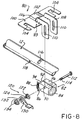
- a third bracket means denoted in general by reference number 80 in Figures 1, 2 and 8 is mounted on the jacket 12 intermediate the first and second ends 20 and 22, respectively, of the jacket 12.
- the third bracket means 80 is fixedly connected to the stationary structure of the vehicle at one portion and is pivotally adjustable with respect to the jacket 12 to enable the jacket 12 to be pivoted about the first end 20 to suit a driver's size and operating position preference.
- the third bracket means includes a clamp block 82 formed of steel or plastic.
- the clamp block 82 has a generally square, cubical form and includes a first longitudinally extending through bore 84.
- the bore 84 is sized to fit about the jacket 12.
- An outwardly extending projection or hanger 86 is mounted on one of the side walls of the clamp block 82 and provides a mounting attachment post for a biasing member, such as a coil spring 88.
- the projection 86 extends through the clamp block 82 into an aperture 118 in the jacket 12.
- a second bore 90 extends through the clamp block 82 transverse to the first bore 84 and is positioned above and in partial communication with the first bore 84 as shown in Figure 8.
- a slot 92 is formed in the clamp block 82 extending from a top surface to and opening into the first bore 84. This forms two top wall portions 94 and 96 in the clamp block 82.
- the third bracket means 80 also includes a mounting plate 100 preferably formed of steel.
- the mounting plate 100 is generally a planar member having a concave central portion 102 which is adapted to engage the circular surface of the jacket 12.
- One end of the biasing spring 88 is mounted in an aperture 89 in the mounting plate 100.
- a pair of opposed slots 104 are formed on opposite sides of the mounting plate 100 and receive retainers 105, Figure 1, and suitable fasteners, not shown, for attaching the mounting plate 100 to the stationary structure of the vehicle.
- the slots 104 and fasteners also provide for controlled collapsibility of the steering column apparatus 10 in that the fasteners slide out of the slots 104 when force is exerted on the steering wheel to collapse the steering column apparatus 10.
- a pair of spaced, L-shaped arms 106 and 108 are integrally formed with and extend downward from the mounting plate 100.
- the arms 106 and 108 are adapted to be disposed adjacent opposite side walls of the clamp block 82.
- An arcuate-shaped slot 110 is formed in each of the arms 106 and 108 to provide for pivotal adjustment of the clamp block 82 with respect to the mounting plate 100, as described immediately below.
- the third bracket means 80 includes releasable lock means for releasably locking the clamp block 82, the mounting plate 100 and the steering column jacket 12 in a one of a plurality of angular positions.
- the releasable lock includes an adjusting bolt 112.
- the adjusting bolt 112 is provided with a plurality of double start external threads 114 extending from an outer end.
- the second transverse bore 90 will be aligned with a transverse slot 116 formed in an upper surface of the steering column jacket 12, as shown in Figure 8.
- the clamp block 82 is also pinned to the steering column jacket 12 by means of the projection or hanger 86 which extends through the clamping block 82 into the aperture 118 in the jacket 12.
- the adjusting bolt 112 extends through the clamp block 82 such that the external threads 114 extend outward from one side wall of the clamp block 82.
- An adjusting nut 120 has an internally threaded bore formed adjacent one end which engages the external threads 114 on the adjusting bolt 112.
- the adjusting nut 120 also includes hex flats 122 and an externally threaded end portion 124.
- the slots 110 in the arms 106 and 108 of the mounting plate 100 slidably engage the flats 122 on the adjusting nut 120 to slidably interconnect the clamping block 82 to the mounting plate 100.
- a pivotal lever 130 includes a toothed aperture 132 which engages the external threads 124 on the adjusting nut 120.
- a lock nut 134 also engages the external threads 124 on the adjusting nut 120 to retain the lever 130 on the adjusting nut 120.
- the lever 130 is movable in any angular amount between a first upper position shown in solid in Figure 2 to a second lower lock position shown in phantom in Figure 2. While being urged clockwise to the lock position, the lever 130 rotates the adjusting nut 120 on the adjusting bolt 112 to force the arms 110 on the mounting plate 100 and the top side wall portions 94 and 96 of the clamping block 82 securely together in a fixed position about the steering column jacket 12. This locks the jacket 12 in a fixed position.
- a coil spring is disposed about one end of the bolt 112 and connected to the lever 130 to exert a slight counterclockwise biasing force on the lever 130.
- the force is sufficient to latch the jacket 12 in the upper angled position shown in solid in Figure 2.
- a slight downward force on the lever 130 will enable the jacket 12 to be moved from the first position to other angular positions.
- an ignition lock and switch assembly 140 is removably attached to the jacket 12, preferably adjacent the second bracket means 60.
- the ignition lock and switch assembly 140 includes a cylindrical housing 142 which receives a conventional ignition lock and switch mechanism.
- the housing 142 includes a generally U-shaped, open-ended sleeve 144 which is adapted to surround a lower portion of the steering column jacket 12.
- a mating arcuate shaped collar 146 is removably connected to the sleeve 144 via fasteners, not shown, to attach the housing 142 to the steering column jacket 12.
- the fasteners may be "break-away" bolts to provide an anti-theft capability.
- the ignition lock and switch assembly housing 142 has been described and illustrated as being separate from the second bracket means 60, it will be understood that the housing 142 may be integrated into a single piece unit with the second bracket means 60.
- the steering column apparatus 10 of the present invention also includes a uniquely constructed steering column shaft 14.
- the steering column shaft 14 is formed as a hollow, tubular member of a high strength material, such as steel.
- the steering column shaft 14 is formed with a first end 154 and an opposed, second end 156.
- a slit is formed in the first end 154 of the shaft 14 extending from the first end 154 along the longitudinal axis of the shaft 14 for a predetermined distance.
- the slit divides the first end 154 of the shaft 14 into two arcuate side wall portions.
- the two arcuate side wall portions are then shaped or bent into two spaced arms 158 and 160, as shown in Figure 10, each having a generally planar end portion and an angular portion integrally connecting the end portion to the remaining portion of the shaft 14.
- a conventional T-drilling operation is then applied to the arms 158 and 160 to form a bore 162 and an enlarged, outwardly extending projection or boss 164 in each of the arms 158 and 160.
- These operations form the first end 154 of the shaft 14 into a conventionally shaped yoke for interconnection to the tail shaft 18 in a normal manner.
- this yoke-shaped end portion is integral with the remainder of the shaft 14 thereby eliminating any separate operations which require attachment of a metallic yoke member to the shaft 14 by additional process steps, such as welding.
- the opposite or second end 156 of the shaft 14 is shaped or formed via normal manufacturing processes into a series of consecutively smaller diameter shoulders 166, 168 and 170. Serrations are formed on the shoulder 168. Further, a steering wheel 16 fastening means, such as a plurality of external threads 174, for example, are formed on the shoulder 170 for interconnection to the steering wheel 16 in a normal manner.
- a spring 176 abuts the first end 154 of the steering column shaft 14 and acts through a washer 178 onto a cone 180 to bias the cone 180 into contact with and to load a stamped bearing 182 mounted in a rubber compliance cup 184.
- An identical, but opposite facing arrangement of a cone 180, a bearing 182, and a compliance cup 184 are disposed over the opposed or second end 156 of the steering column shaft 14 and held in place by a spacer 186 and a retainer clip or snap ring 188 to mount the shaft 14 in the jacket 12 and to maintain the concentricity of the shaft 14 within the jacket 12.
- First and second bracket means are fitted into opposite ends of the steering column jacket and provide interconnection of the steering column jacket to stationary vehicle structure and the vehicle steering wheel.
- a third bracket means is mounted to the jacket to provide tilting characteristics to the steering column apparatus.
- the steering column shaft in the steering column apparatus of the present invention is uniquely constructed from a one-piece, integral hollow tubular member.
- the yoke-shaped end portion at one end of the shaft and the threaded end portion at the opposite end of the shaft are integrally formed in the hollow tubular member thereby eliminating the use of additional components and the normal welding operations employed to mount these components onto a conventional steering column shaft. This results in a steering column assembly having less weight, a lower manufacturing cost and greater reliability than previously constructed steering column apparatus.
Landscapes
- Engineering & Computer Science (AREA)
- Chemical & Material Sciences (AREA)
- Combustion & Propulsion (AREA)
- Transportation (AREA)
- Mechanical Engineering (AREA)
- Steering Controls (AREA)
Abstract
Description
- The present invention relates, in general, to steering columns for motor vehicles.
- Conventional steering column apparatus or assemblies for motor vehicles include an elongated, axial steering column shaft which is connected at one end to a steering wheel and at a lower end to a tail shaft. A jacket concentrically surrounds at least a portion of the steering column shaft, with the ends of the steering column shaft extending outward from opposed ends of the jacket.
- Various brackets are mounted on the jacket to mount the jacket in the vehicle and to attach various devices, such as an ignition lock, steering column switch modules and control levers, etc., to the jacket. For tiltable steering columns, a bracket containing a pivot and a release lock lever mechanism is also mounted on the jacket, typically intermediate the ends of the jacket to provide selective tilting of the steering column apparatus to accommodate a driver's size and driving position preference.
- Since the steering column jacket is made of metal, i.e., steel, the brackets are typically attached to the jacket via welding. However, this creates several disadvantages. The brackets mounted on the jacket are also made of metal which adds significant weight to the steering column apparatus. Welding operations are also costly in terms of labor and/or welding equipment. Welding also has uncertain reliability since there is no convenient way to determine if a proper high strength weld has been made, without resorting to destructive testing. Misaligned brackets or brackets attached to the jacket with low strength welds result in scrap which adds to overall costs.
- The construction of the steering column shaft in a conventional steering column apparatus encounters similar problems. Typically, the steering column shaft is a solid, metallic tubular member. The lower yoke and upper threaded member separate members which are welded to the shaft to connect the steering column shaft to the lower tail shaft and the steering wheel, respectively. This entails the use of additional, separate elements which results in a higher overall weight for the steering column shaft, higher cost due the use of additional components and potential reliability problems when the yoke and threaded member are welded to the tubular shaft.
- Thus, it would be desirable to provide a steering column apparatus which is constructed without any welds. It would also be desirable to provide a steering column apparatus in which the various mounting, tilt and accessory brackets are attached to the steering column jacket without the use of welding operations. It would also be desirable to provide a steering column apparatus which includes a steering column shaft which is constructed without the use of welding. It would also be desirable to provide a steering column shaft which is constructed as a one-piece, integral member without the use of separate members welded to a tubular shaft as is conventional. Finally, it would be desirable to provide a steering column apparatus which has a lower manufacturing cost, lower weight, greater manufacturing adjustability and greater reliability than conventionally constructed steering column apparatus.
- The present invention is a vehicle steering column apparatus which provides many significant advantages over conventional steering column apparatus.
- In a preferred embodiment, the vehicle steering column apparatus includes a hollow tubular jacket having first and second opposed ends. A first bracket means is fitted into the first end of the jacket and is fixedly connectible to the vehicle. A second bracket means is fitted into the second end of the jacket and removably receives a lever controlled steering column switch means for operating various electrical devices on the vehicle upon selective movement of the lever. A steering column shaft is rotatably mounted within the jacket and extends outward from the first and second ends of the jacket for connection to the vehicle steering wheel at one end and to the vehicle steering linkage tail shaft at the other end.
- A third bracket means may be mounted intermediate the first and second ends of the jacket and to the vehicle. The third bracket means preferably includes pivot means for pivoting the steering column jacket about the first end thereof to any desired angular position.
- The steering column shaft is uniquely constructed as a one-piece, integral member by first slitting one end of the steering column shaft and bending the side wall portions formed by the slit into two spaced arms. A bore and a outwardly extending projection are formed in each of the arms by a T-drill operation. This forms an integral yoke at one end of the steering column shaft to enable the steering column shaft to be connected to a tail shaft on the vehicle. However, the yoke is integral with and formed as a non-separate extension of the steering column shaft thereby eliminating the need for a separate yoke member which is conventionally welded to the steering column shaft. This eliminates the welding operation thereby providing a lower cost steering column shaft which has greater reliability than previously constructed steering column shafts. The opposite end of the steering column shaft is formed for direct connection to a vehicle steering wheel thereby eliminating a separate threaded member which is conventionally welded to the shaft.
- The present invention also comprises a unique method of constructing a vehicle steering column apparatus in which first and second bracket means are fitted into the first and second ends of a hollow, tubular jacket. These unique steps eliminate the need for welding operations previously employed to attach the first and second brackets to the steering column jacket. This results in a significant reduction in weight and cost for the steering column apparatus of the present invention as compared to previously constructed steering column apparatus. Further, since no welding operations are employed, the reliability of the steering column shaft is greatly improved.
- Finally, the present invention encompasses a unique method of constructing a steering column shaft. This method includes the steps of slitting a first end of a hollow tubular shaft. The side wall portions formed by the slit are bent outward to form two spaced arms which are an integral extension of the hollow shaft. A boss and bore are formed in each arm by a T-drill operation to form a yoke at the first end of the steering column shaft. Threads are formed on the second end of the hollow shaft for connection to a steering wheel.
- This method creates a one-piece, hollow steering column shaft which includes integral yoke and threaded end portions and eliminates the need for welding a separate yoke and a separate threaded member to the steering column shaft as is conventional.
- The various features, advantages and other uses of the present invention will become more apparent by referring to the following detailed description and drawing in which:
- Figure 1 is a perspective view of a steering column apparatus constructed in accordance with the teachings of the present invention;
- Figure 2 is a partial, side elevational view of the steering column apparatus shown in Figure 1;
- Figure 3 is an exploded, perspective view of the first bracket means shown in Figure 1;
- Figure 4 is a perspective view of the second bracket means shown in Figure 1;
- Figure 5 is a longitudinally cross-sectioned, exploded view showing the mounting of the second bracket means to the steering column jacket;
- Figure 6 is a rear elevational view of the second bracket means showing the mounting of the steering column switch assembly therein;
- Figure 7 is a partially cross-sectioned, side elevational view of the opposed ends of the steering column apparatus shown in Figure 1;
- Figure 8 is an exploded, perspective view of the third bracket means;
- Figure 9 is an exploded, perspective view of the ignition lock shown in Figure 1;
- Figure 10 is a partially cross-sectioned, side elevational view of the steering column shaft employed in the steering column apparatus shown in Figure 1; and
- Figure 11 is an exploded, perspective view of the bearing assembly employed with the steering column shaft.
- Referring now to the drawing, and to Figure 1 in particular, there is depicted a steering column apparatus 10 for use in a motor vehicle, such as an automobile. The steering column apparatus 10 is uniquely constructed with a low cost, low weight and high reliability.
- As shown in Figure 1, and in greater detail in Figures 2 and 7, the steering column apparatus 10 includes a
jacket 12 which concentrically surrounds asteering column shaft 14 connected at a first or upper end to asteering wheel 16 and at a second, opposed lower end to atail shaft 18 which is in turn connected to the conventional vehicle steering linkage, not shown. Various brackets are mounted to thejacket 12 to attach thejacket 12 and the entire steering column apparatus 10 to the stationary structure of the vehicle and, as described in a preferred embodiment, to provide selective pivoting or tilting of the steering column apparatus 10 to suit a driver's size and operating position preference. - The
jacket 12 is formed as a hollow, tubular member from a high strength material, such as steel. Thejacket 12 has afirst end 20 and an opposed,second end 22, as shown in Figure 7. Several slots and through bores are formed in thejacket 12, as will be described in greater detail hereafter, for mounting various brackets to thejacket 12. Although thejacket 12 is preferably a one-piece member as shown in Figures 1 and 7, thejacket 12 may also be formed of two or more tubular members unitarily interconnected or telescopingly arranged. - As shown in Figures 1 and 2, and in greater detail in Figures 3 and 7, the steering column apparatus 10 includes a first bracket means 30 which is fitted into the
first end 20 of thejacket 12 and is fixedly connectible to the stationary structure of the vehicle for mounting one end of thejacket 12 to the vehicle. In a preferred embodiment, the first bracket means 30 is constructed to provide pivotal movement of thejacket 12 and the entire steering column assembly 10 about the first end of thejacket 12 so as to enable selective tilting to the steering column apparatus 10 as described in greater detail hereafter. - In the preferred embodiment, the first bracket means 30 includes a
yoke 32 which is formed with two spaced,opposed legs central bight section 37. Outwardly extending projections ortrunnions 40 are formed at one end of each of thearms trunnion 40. Thetrunnions 40 are designed to shear under a longitudinal force exerted on thejacket 12 to provide energy management during a collision. Thebores 42 are variable in diameter to provide a tunable shear force for thetrunnions 40. A clevis pin, not shown, may be inserted into thebores 42 for additional reinforcement. - A
tubular boss 38 extends outward from thecentral bight section 37. Theboss 38 is sized so as to be fitted, such as by a press fit, for example, into thefirst end 20 of thejacket 12. - The
yoke 32 is preferably injection molded from a suitable, high strength plastic. For additional strength, a thin metallic strip may be insert molded into thearms central bight section 37. - The first bracket means 30 also includes a
first plate 44, Thefirst plate 44 is formed with a planarcentral portion 46 and two, opposedside flanges Slots 52 are formed in each of theside flanges - The
first plate 44 also includes a pair of dependingarms 54. Anaperture 56 is formed in each of thearms 54 and is pivotally mounted about one of thetrunnions 40 on theyoke 32 to pivotally interconnect thefirst plate 44 and theyoke 32. In this manner, the first orlower end 20 of thejacket 12 is pivotally mounted to the stationary structure of the vehicle, such as the vehicle body panels adjacent the firewall in the interior passenger compartment of the vehicle. - A second bracket means 60 is mounted to the
jacket 12 by being fitted into thesecond end 22 of thejacket 12. As shown in Figure 1, and in greater detail in Figures 4-7, the second bracket means 60 includes abase 62. A firstannular flange 64 extends outward from one side of thebase 62 and concentrically surrounds atubular sleeve 66 which also extends outward from thebase 62. Thesleeve 66 is adapted to be fitted into thesecond end 22 of thejacket 12 as shown in Figure 5. By way of example only, thesleeve 66 is sized and shaped to be press fit into thesecond end 22 of thejacket 12. A projection or key 68 is formed on an upper surface of thesleeve 66 and engages a complementarily-shapedslot 70 which opens inward from thesecond end 22 of thejacket 12 to stationarily position thesleeve 66 with respect to thejacket 12. - A second
annular flange 72 extends outward from the opposite surface of thebase 62 and, in electrical air bag steering column applications, receives the air bag electrical interface commonly referred to as the "clockspring". Anapparatus 73 is formed in thebase 62 concentrically within the secondannular flange 72 and receives a collar denoted in general byreference number 74 which acts as a bearing for one end of the steering column shaft, as described hereafter. - As shown in Figure 6, the
base 62 includes means for mounting a steering column switch means to thebase 62. By way of example, the mounting means comprises spaced pairs ofprojections 74 which slidingly receive a steering columnswitch assembly housing 76.Separate housings 76 may be mounted on opposite sides of thesleeve 66. Thehousing 76 carries a control lever or stalk 78 which operates actuating mechanisms mounted within thehousing 76. The actuating mechanisms control the operation and switching ofvarious switch modules housing 76. Theswitch modules housing 76 can be had by referring to United States Patent Application Serial No. 07/529,096, the contents of which are incorporated herein by reference. Other mounting means, such as fasteners, clamps, etc., may also be employed to mount the steering column switch means to thebase 52 of the second bracket means 60. - The second bracket means 60 is preferably formed as an injection molded component from a suitable plastic, such as glass reinforced nylon.
- In order to provide a tilting capability to the steering column apparatus 10, a third bracket means denoted in general by
reference number 80 in Figures 1, 2 and 8 is mounted on thejacket 12 intermediate the first and second ends 20 and 22, respectively, of thejacket 12. The third bracket means 80 is fixedly connected to the stationary structure of the vehicle at one portion and is pivotally adjustable with respect to thejacket 12 to enable thejacket 12 to be pivoted about thefirst end 20 to suit a driver's size and operating position preference. - The third bracket means includes a
clamp block 82 formed of steel or plastic. Theclamp block 82 has a generally square, cubical form and includes a first longitudinally extending throughbore 84. Thebore 84 is sized to fit about thejacket 12. - An outwardly extending projection or
hanger 86 is mounted on one of the side walls of theclamp block 82 and provides a mounting attachment post for a biasing member, such as acoil spring 88. Theprojection 86 extends through theclamp block 82 into anaperture 118 in thejacket 12. - A
second bore 90 extends through theclamp block 82 transverse to thefirst bore 84 and is positioned above and in partial communication with thefirst bore 84 as shown in Figure 8. Aslot 92 is formed in theclamp block 82 extending from a top surface to and opening into thefirst bore 84. This forms twotop wall portions clamp block 82. - The third bracket means 80 also includes a mounting
plate 100 preferably formed of steel. The mountingplate 100 is generally a planar member having a concavecentral portion 102 which is adapted to engage the circular surface of thejacket 12. One end of the biasingspring 88 is mounted in anaperture 89 in the mountingplate 100. - A pair of
opposed slots 104 are formed on opposite sides of the mountingplate 100 and receiveretainers 105, Figure 1, and suitable fasteners, not shown, for attaching the mountingplate 100 to the stationary structure of the vehicle. Theslots 104 and fasteners also provide for controlled collapsibility of the steering column apparatus 10 in that the fasteners slide out of theslots 104 when force is exerted on the steering wheel to collapse the steering column apparatus 10. - A pair of spaced, L-shaped
arms plate 100. Thearms clamp block 82. An arcuate-shapedslot 110 is formed in each of thearms clamp block 82 with respect to the mountingplate 100, as described immediately below. - The third bracket means 80 includes releasable lock means for releasably locking the
clamp block 82, the mountingplate 100 and thesteering column jacket 12 in a one of a plurality of angular positions. The releasable lock includes an adjustingbolt 112. Preferably, the adjustingbolt 112 is provided with a plurality of double start external threads 114 extending from an outer end. - When the
clamp block 82 is disposed about thesteering column jacket 12, the second transverse bore 90 will be aligned with atransverse slot 116 formed in an upper surface of thesteering column jacket 12, as shown in Figure 8. Theclamp block 82 is also pinned to thesteering column jacket 12 by means of the projection orhanger 86 which extends through the clampingblock 82 into theaperture 118 in thejacket 12. The adjustingbolt 112 extends through theclamp block 82 such that the external threads 114 extend outward from one side wall of theclamp block 82. An adjustingnut 120 has an internally threaded bore formed adjacent one end which engages the external threads 114 on the adjustingbolt 112. The adjustingnut 120 also includeshex flats 122 and an externally threadedend portion 124. Theslots 110 in thearms plate 100 slidably engage theflats 122 on the adjustingnut 120 to slidably interconnect the clampingblock 82 to the mountingplate 100. - A
pivotal lever 130 includes atoothed aperture 132 which engages theexternal threads 124 on the adjustingnut 120. Alock nut 134 also engages theexternal threads 124 on the adjustingnut 120 to retain thelever 130 on the adjustingnut 120. - In operation, as shown in Figure 2, the
lever 130 is movable in any angular amount between a first upper position shown in solid in Figure 2 to a second lower lock position shown in phantom in Figure 2. While being urged clockwise to the lock position, thelever 130 rotates the adjustingnut 120 on the adjustingbolt 112 to force thearms 110 on the mountingplate 100 and the topside wall portions block 82 securely together in a fixed position about thesteering column jacket 12. This locks thejacket 12 in a fixed position. Counterclockwise rotation of thelever 130 toward the first position releases the force on the adjustingnut 120 and enables thesteering column jacket 12 to be pivoted about thefirst end 20 through a plurality of angular positions toward a bottommost position shown in phantom in Figure 2. In any angular position of thejacket 12 between the positions shown by solid and phantom lines in Figure 2, thelever 130 may be rotated to the second lock position to retain thejacket 12 and the entire steering column apparatus 10 in the desired angular position to suit a driver's preference and/or size. - A coil spring, not shown, is disposed about one end of the
bolt 112 and connected to thelever 130 to exert a slight counterclockwise biasing force on thelever 130. The force is sufficient to latch thejacket 12 in the upper angled position shown in solid in Figure 2. A slight downward force on thelever 130 will enable thejacket 12 to be moved from the first position to other angular positions. - Additional brackets or devices may also be mounted to the
steering column jacket 12. As shown in Figure 1, and in greater detail in Figure 9, an ignition lock and switchassembly 140 is removably attached to thejacket 12, preferably adjacent the second bracket means 60. The ignition lock and switchassembly 140 includes acylindrical housing 142 which receives a conventional ignition lock and switch mechanism. Thehousing 142 includes a generally U-shaped, open-endedsleeve 144 which is adapted to surround a lower portion of thesteering column jacket 12. A mating arcuate shapedcollar 146 is removably connected to thesleeve 144 via fasteners, not shown, to attach thehousing 142 to thesteering column jacket 12. The fasteners may be "break-away" bolts to provide an anti-theft capability. - Although the ignition lock and switch
assembly housing 142 has been described and illustrated as being separate from the second bracket means 60, it will be understood that thehousing 142 may be integrated into a single piece unit with the second bracket means 60. - The steering column apparatus 10 of the present invention also includes a uniquely constructed
steering column shaft 14. As shown in Figures 7 and 10, thesteering column shaft 14 is formed as a hollow, tubular member of a high strength material, such as steel. Thesteering column shaft 14 is formed with afirst end 154 and an opposed,second end 156. - According to the method of constructing the
steering column shaft 14 of the present invention, a slit is formed in thefirst end 154 of theshaft 14 extending from thefirst end 154 along the longitudinal axis of theshaft 14 for a predetermined distance. The slit divides thefirst end 154 of theshaft 14 into two arcuate side wall portions. The two arcuate side wall portions are then shaped or bent into two spacedarms shaft 14. - A conventional T-drilling operation is then applied to the
arms bore 162 and an enlarged, outwardly extending projection orboss 164 in each of thearms first end 154 of theshaft 14 into a conventionally shaped yoke for interconnection to thetail shaft 18 in a normal manner. However, this yoke-shaped end portion is integral with the remainder of theshaft 14 thereby eliminating any separate operations which require attachment of a metallic yoke member to theshaft 14 by additional process steps, such as welding. - The opposite or
second end 156 of theshaft 14 is shaped or formed via normal manufacturing processes into a series of consecutively smaller diameter shoulders 166, 168 and 170. Serrations are formed on theshoulder 168. Further, asteering wheel 16 fastening means, such as a plurality ofexternal threads 174, for example, are formed on theshoulder 170 for interconnection to thesteering wheel 16 in a normal manner. - As shown in Figures 7 and 11, a
spring 176 abuts thefirst end 154 of thesteering column shaft 14 and acts through awasher 178 onto acone 180 to bias thecone 180 into contact with and to load a stampedbearing 182 mounted in arubber compliance cup 184. An identical, but opposite facing arrangement of acone 180, abearing 182, and acompliance cup 184 are disposed over the opposed orsecond end 156 of thesteering column shaft 14 and held in place by aspacer 186 and a retainer clip orsnap ring 188 to mount theshaft 14 in thejacket 12 and to maintain the concentricity of theshaft 14 within thejacket 12. - In summary, there has been disclosed a unique steering column apparatus for motor vehicles which is constructed without any welding operations. First and second bracket means are fitted into opposite ends of the steering column jacket and provide interconnection of the steering column jacket to stationary vehicle structure and the vehicle steering wheel. A third bracket means is mounted to the jacket to provide tilting characteristics to the steering column apparatus.
- The steering column shaft in the steering column apparatus of the present invention is uniquely constructed from a one-piece, integral hollow tubular member. The yoke-shaped end portion at one end of the shaft and the threaded end portion at the opposite end of the shaft are integrally formed in the hollow tubular member thereby eliminating the use of additional components and the normal welding operations employed to mount these components onto a conventional steering column shaft. This results in a steering column assembly having less weight, a lower manufacturing cost and greater reliability than previously constructed steering column apparatus.
Claims (21)
- A vehicle steering column apparatus (10) comprising:
a hollow, tubular jacket (12) having first and second opposed ends (20,22);
first bracket means (30) fit into the first end (20) of the jacket (12), the first bracket means (30) being fixedly connectible to the vehicle;
second bracket means (60) fit into the second end (22) of the jacket (12), the second bracket means (60) removably receiving a lever controlled (78) steering column switch means (76) for operating vehicle devices upon selected pivotal movement of the steering column switch means lever (78); and
a steering column shaft (14) rotatably mounted in the jacket (12) and extending outward from the first (20) and second ends (22) of the jacket. - The vehicle steering column apparatus of Claim 1 wherein the first bracket means (30) comprises:
a yoke (32), the yoke (32) including:
two spaced arms (34,36) interconnected by a central end portion (37); and
a boss (38) extending outward from the central end portion (37) away from the two arms (34,36) and fitted into the first end (20) of the jacket (12);
a mounting plate (44) connectible to the vehicle;
a pair of depending arms extending (54) from the mounting plate (44) and pivotally connected to the two arms (34,36) of the yoke to pivotally connect the first end (20) of the jacket (12) to the vehicle. - The vehicle steering column control apparatus of Claim 2 wherein the yoke (32) is formed of a molded plastic.
- The vehicle steering column apparatus of Claim 1 or 2 wherein the second bracket means (60) comprises:
a base (62);
a sleeve (66) extending outward from one surface of the base (62) and fitted into the second end (22) of the jacket; and
means for releasably mounting the steering column switch means (76) to the base (62). - The vehicle steering column apparatus of one of the Claims 1 till 4 further including:
third bracket means (80) mounted to the jacket (12) intermediate the first and second ends (20,22) of the jacket (12), the third means (80) being fixedly connectible to the vehicle;
the third bracket means (80) including pivot (130) means for pivoting the jacket (12) about the first end (20); and
lock means (134) for locking the pivot means (130) in a predetermined position. - The vehicle steering column apparatus of claim 5 wherein the third bracket means (80) and the lock means (34) comprises:
a clamp block (82) having a central bore (84) extending longitudinally therethrough;
a slot (92) formed in the clamp block (82) and disposed in communication with the central bore (84) in the block (82), the slot (92) separating one wall of the clamp block into two spaced wall portions (94,96);
a transverse bore (90) extending through the clamp block (82);
a threaded bolt (112) having an externally threaded end portion (114) extending through the transverse bore (90) in the clamp block (82);
an adjustable nut (120) mounted on the end (114) of the bolt (112) external from the clamp block (82);
an upper bracket (80) connected to the vehicle;
at least one arm (106,108) extending from the upper bracket (80);
a slot (110) formed in the arm for receiving the threaded bolt (112) therethrough; and
a pivotal lever (130) mounted on the adjusting nut (120) for moving the adjusting nut (120) on pivotal movement of the lever (130) between a first position locking the clamp block (82), the upper bracket (80) and the steering column jacket (12) in a fixed position relative to each other and a second position allowing the steering column jacket (12) to pivot about its first end (20) relative to the upper bracket (80). - The vehicle steering column apparatus of Claim 6 wherein the lever (130) is manually pivotal.
- The vehicle steering column apparatus of one of the Claims 1 till 7 further comprising:
ignition switch means (140) mounted on the jacket (12) for receiving a vehicle ignition switch. - The vehicle steering column apparatus of one of the Claims 1 till 8 wherein the steering column shaft (10) comprises:
a hollow, tubular member (14) having first and second opposed ends (154,156);
spaced first and second arms (158,160) integrally formed in the first end (154) of the shaft (12) as an integral extension of the tubular member (14);
a bore (162) formed in each of the first and second arms (158,160) coaxially aligned with the bore in the opposed arm (158,160); and
means (174), formed on the second end (156) of the tubular member (14) for mounting a vehicle steering wheel (16) on the tubular member (14). - The vehicle steering column apparatus of one of the Claims 1 till 9 wherein the tubular jacket (12) comprises a one-piece member.
- The vehicle steering column apparatus of one of the Claims 1 till 10 wherein the first bracket means (30) is press fit into the first end (20) of the jacket (12).
- The vehicle steering column apparatus (10) of one of the Claims 1 till 11 wherein the second bracket means (60) is press fit into the second end (12) of the jacket (12).
- A vehicle steering column apparatus (10) comprising:
a hollow, tubular jacket (12) having first and second opposed ends (20,22);
first bracket means (30) mounted on the first end (20) of the jacket (12) and fixedly connectible to the vehicle;
second bracket means (60), mounted on the second end (22) of the jacket (12), for removably receiving a lever controlled (78) steering column switch means (76) for operating vehicle electrical devices (79,81,83) upon selective pivotal movement of the steering column switch means lever (78); and
a steering column shaft (14) rotatably mounted in the tubular jacket (12), the steering column shaft (14) including:
a hollow, tubular member (14) having a first and second opposed ends (154,156);
spaced first and second arms (158,160) integrally formed in the first end (154) of the tubular member (14) as an integral extension of the tubular member (14);
a bore (162) formed in each of the first and second arms (158,160) co-axially aligned with the bore (162) in the opposed arm (158,160); and
means (174), formed on the second end (156) of the tubular member (14), for mounting a vehicle steering wheel (16) thereon. - The vehicle steering column apparatus of Claim 13 further comprising:
third bracket means (80) mounted to the jacket (12) intermediate the first and second ends (20,22) of the jacket (12), the third means (80) being fixedly connectible to the vehicle; and
the third bracket means (80) including pivot means (130) for pivoting the jacket (12) about the first end (20). - The vehicle steering column apparatus (10) of Claim 14 wherein the third bracket means (80) comprises:
a clamp block (82) having a central bore (84) extending longitudinally therethrough;
a slot (92) formed in the clamp block (82) and disposed in communication with the central bore (84) in the block (82), the slot (92) separating one wall of the clamp block into two spaced wall portions (94,96);
a transverse bore (90) extending through the clamp block (82);
a threaded bolt (112) having an externally threaded end portion (114) extending through the transverse bore (90) in the clamp block (82);
an adjustable nut (120) mounted on the end (114) of the bolt (112) external from the clamp block (82);
an upper bracket (80) connected to the vehicle;
at least one arm (106,108) extending from the upper bracket (80);
a slot (110) formed in the arm for receiving the threaded bolt (112) therethrough; and
a pivotal lever (130) mounted on the adjusting nut (120) for moving the adjusting nut (120) on pivotal movement of the lever (130) between a first position locking the clamp block (82), the upper bracket (80) and the steering column jacket (12) in a fixed position relative to each other and a second position allowing the steering column jacket (12) to pivot about its first end (20) relative to the upper bracket (80). - A method of making a vehicle steering column apparatus (10) comprising the steps of:
forming a hollow, tubular jacket (12) having first and second opposed ends (20,22);
fitting a first bracket (30) means releasably connectible to the vehicle into the first end (20) of the jacket (12);
fitting a second bracket (60) means into the second end (22) of the jacket (12), the second bracket means (60) removably receiving a steering column switch means (76); and
mounting a rotatable steering column shaft (14) within the jacket (12), with each end (154,156) of the steering column shaft extending outward from the first and second ends (20,22) of the jacket (12), respectively. - The method of Claim 16 further comprising the step of:
removably mounting a third bracket means (80) to the jacket (12) intermediate the first and second ends (20,22) of the jacket (12), the third bracket means (80) including pivot means (130) connectible to the vehicle for pivoting the jacket (12) about the first end (20) of the jacket. - The method of Claim 16 further comprising the steps of:
forming the steering column shaft (14) as a hollow, tubular member having first and second opposed ends (154,156);
slitting the first end (154) of the tubular member (14) to form first and second opposed, separate, side wall portions (158,160);
bending the first and second side wall portions apart to form first and second spaced, opposed arms (158,160), each having planar end portions and an arcuate portion connecting the end portions to the tubular member;
T-drilling a boss (164) and a bore (162) in each of the end portions of the first and second arms (158,160), the bores (162) in each of the first and second arms being co-axially aligned; and
forming a steering wheel means fastening means (174) on the second end (156) of the tubular member (14). - The method of Claim 16 wherein the step of fitting the first bracket means (30) comprises the step of press fitting the first bracket means (30) into the first end (20) of the jacket (12).
- The method of Claim 16 wherein the step of fitting the second (60) bracket means comprises the step of press fitting the second bracket means (60) into the second end (22) of the jacket (12).
- A method of making a vehicle steering column apparatus comprising the steps of:
forming a hollow, tubular jacket (12) having first and second opposed ends (20,22);
mounting a first bracket means (30) releasably connectible to the vehicle onto the first end (20) of the jacket (12);
mounting a second bracket means onto the second end (22) of the jacket (12), the second bracket means (60) removably receiving a steering column switch means (76);
forming a steering column shaft (14) as a hollow, tubular member having first and second opposed ends (154,156);
slitting the first end (154) of the tubular member (14) to form first and second opposed, separate, side wall portions (158,160);
bending the first and second side wall portions apart to form first and second spaced, opposed arms (158,160), each having planar end portions and an arcuate portion connecting the end portions to the tubular member;
T-drilling a boss (164) and a bore (162) in each of the end portions of the first and second arms (158,160), the bores in each of the first and second arms being co-axially aligned; and
forming a plurality of external threads (174) on the second end (156) of the tubular member (14).
Applications Claiming Priority (2)
| Application Number | Priority Date | Filing Date | Title |
|---|---|---|---|
| US07/644,719 US5090730A (en) | 1991-01-23 | 1991-01-23 | Vehicle steering column apparatus |
| US644719 | 1991-01-23 |
Publications (2)
| Publication Number | Publication Date |
|---|---|
| EP0496387A2 true EP0496387A2 (en) | 1992-07-29 |
| EP0496387A3 EP0496387A3 (en) | 1993-07-07 |
Family
ID=24586069
Family Applications (1)
| Application Number | Title | Priority Date | Filing Date |
|---|---|---|---|
| EP19920101032 Ceased EP0496387A3 (en) | 1991-01-23 | 1992-01-23 | Vehicle steering column apparatus |
Country Status (3)
| Country | Link |
|---|---|
| US (1) | US5090730A (en) |
| EP (1) | EP0496387A3 (en) |
| JP (1) | JPH06211137A (en) |
Cited By (4)
| Publication number | Priority date | Publication date | Assignee | Title |
|---|---|---|---|---|
| FR2726527A1 (en) * | 1994-11-07 | 1996-05-10 | Renault | STEERING ASSEMBLY FOR MOTOR VEHICLE |
| WO2001081149A2 (en) | 2000-04-20 | 2001-11-01 | Thyssenkrupp Presta Aktiengesellschaft | Adjusting and fixing device for a steering shaft, whose height and/or length can be adjusted |
| CN103707918A (en) * | 2012-10-05 | 2014-04-09 | 通用汽车环球科技运作有限责任公司 | Steering column assembly for motor vehicle |
| US11415031B2 (en) | 2017-07-21 | 2022-08-16 | Bosal Emission Control Systems Nv | Method for forming a collar in a muffler housing |
Families Citing this family (27)
| Publication number | Priority date | Publication date | Assignee | Title |
|---|---|---|---|---|
| US5211042A (en) * | 1991-03-29 | 1993-05-18 | Nissan Motor Co., Ltd. | Steering locking apparatus with tiltable steering mechanism |
| US5509325A (en) * | 1994-05-18 | 1996-04-23 | Chrysler Corporation | Steering column assembly |
| DE4422305C2 (en) † | 1994-06-17 | 1996-06-20 | Kostal Leopold Gmbh & Co Kg | Electrical equipment |
| JP3415953B2 (en) * | 1995-02-03 | 2003-06-09 | 日本精工株式会社 | Steering column support device |
| US5645299A (en) * | 1996-05-31 | 1997-07-08 | Trw Inc. | Steering column support |
| GB9704808D0 (en) * | 1997-03-07 | 1997-04-23 | Lucas Ind Plc | Improvements relating to steering assemblies |
| US6019391A (en) * | 1998-05-04 | 2000-02-01 | General Motors Corporation | Steering column for motor vehicle |
| ES2157762B1 (en) * | 1999-02-26 | 2002-02-16 | Castellon Melchor Daumal | LONGITUDINAL GUIDANCE CONTROL SYSTEM FOR TELESCOPIC TREES AND / OR ASSEMBLIES WITH COLLAPSE MECHANISMS IN STEERING COLUMNS FOR AUTOMOBILE VEHICLES. |
| US20040231917A1 (en) * | 1999-12-06 | 2004-11-25 | Chick Mark C. | Scaffold moving device |
| US6533067B2 (en) * | 1999-12-06 | 2003-03-18 | Mark C. Chick | Scaffold moving device |
| JP5195827B2 (en) * | 2000-02-15 | 2013-05-15 | 日本精工株式会社 | Vehicle steering device |
| EP1125820B2 (en) * | 2000-02-15 | 2012-07-11 | Nsk Ltd | Steering device for car |
| US6349611B1 (en) | 2000-03-20 | 2002-02-26 | L & P Property Management Company | Cable operated actuator assembly |
| US6237956B1 (en) * | 2000-04-17 | 2001-05-29 | Lear Corporation | Steering column support bracket |
| US20030172765A1 (en) * | 2000-04-20 | 2003-09-18 | Roland Heiml | Adjusting and fixing device for a steering shaft, whose height and/or length can be adjusted |
| US6829961B2 (en) * | 2001-10-09 | 2004-12-14 | Trw Inc. | Intermediate steering column |
| DE602004024090D1 (en) * | 2003-09-25 | 2009-12-24 | Nsk Ltd | ELECTRIC POWER STEERING DEVICE |
| US7077432B2 (en) * | 2003-09-30 | 2006-07-18 | Delphi Technologies, Inc. | Steering column assembly having break-away device |
| GB0525850D0 (en) * | 2005-09-01 | 2006-02-01 | Trw Lucasvarity Electric Steer | A Steering Column Assembly |
| US7574940B2 (en) * | 2005-11-23 | 2009-08-18 | Delphi Technologies, Inc. | Steering column assembly including anti-rotation device |
| US20070245845A1 (en) * | 2006-04-20 | 2007-10-25 | Ridgway Jason R | Steering column assembly for a vehicle |
| JP5429110B2 (en) * | 2010-08-20 | 2014-02-26 | 日本精工株式会社 | Steering device |
| JP5429109B2 (en) * | 2010-08-20 | 2014-02-26 | 日本精工株式会社 | Steering device |
| CN103189263B (en) * | 2011-10-11 | 2015-08-05 | 日本精工株式会社 | Steering gear and manufacture method thereof |
| EP3052370B1 (en) | 2013-10-04 | 2017-06-14 | NSK Americas, Inc. | Collapsible steering column assembly |
| DE102015220934B3 (en) * | 2015-10-27 | 2016-11-24 | Thyssenkrupp Ag | Steering column for a motor vehicle and method for producing a steering column |
| KR102917560B1 (en) * | 2020-11-25 | 2026-01-27 | 남양넥스모 주식회사 | Manufacturing method of steering column mounting bracket |
Citations (1)
| Publication number | Priority date | Publication date | Assignee | Title |
|---|---|---|---|---|
| US5049706A (en) | 1990-05-25 | 1991-09-17 | Rocher Daniel J Du | Multifunction steering column switch |
Family Cites Families (37)
| Publication number | Priority date | Publication date | Assignee | Title |
|---|---|---|---|---|
| US725574A (en) * | 1902-04-29 | 1903-04-14 | Albert N Locke | Motor-vehicle. |
| US2611047A (en) * | 1950-06-08 | 1952-09-16 | Gen Motors Corp | Direction signaling device |
| US2781429A (en) * | 1954-02-08 | 1957-02-12 | Northeast Capital Corp | Directional signal switch |
| US2830146A (en) * | 1955-03-01 | 1958-04-08 | Sparks Withington Co | Directional signal switch mechanism |
| GB1292438A (en) * | 1969-08-08 | 1972-10-11 | Daimler Benz Ag | Improvements relating to steering-column assemblies |
| GB1463819A (en) * | 1973-12-10 | 1977-02-09 | Cam Gears Ltd | Supports for steering columns |
| GB1474150A (en) * | 1974-08-12 | 1977-05-18 | Rau Swf Autozubehoer | Steering column switch for automotive vehicles |
| FR2360454A1 (en) * | 1976-08-05 | 1978-03-03 | Chrysler France | Adjustable car steering column assembly - has movable steering column support and fixed support on car, both supports having slots for adjusting rake and length |
| US4086825A (en) * | 1976-11-18 | 1978-05-02 | Ford Motor Company | Steering column assemblies |
| US4175449A (en) * | 1977-02-09 | 1979-11-27 | Ford Motor Company | Tilt cab steering column |
| US4218595A (en) * | 1977-02-18 | 1980-08-19 | Niles Parts Co., Ltd. | Composite switch device mounted to the steering shaft of automobiles |
| DE2828592C2 (en) * | 1978-06-29 | 1980-01-03 | Fa. Leopold Kostal, 5880 Luedenscheid | Steering column switches for automobiles |
| US4217792A (en) * | 1978-08-24 | 1980-08-19 | General Motors Corporation | Steering column for vehicles |
| JPS5551664A (en) * | 1978-10-11 | 1980-04-15 | Nissan Motor Co Ltd | Tilt angle adjusting apparatus of tilt handle |
| US4257624A (en) * | 1978-12-22 | 1981-03-24 | Allis-Chalmers Corporation | Extendible steering column |
| DE2905130C2 (en) * | 1979-02-10 | 1983-01-27 | Fa. Leopold Kostal, 5880 Lüdenscheid | Jacketed pipe on the steering column of motor vehicles |
| DE2934473C2 (en) * | 1979-08-25 | 1982-12-16 | Zahnradfabrik Friedrichshafen Ag, 7990 Friedrichshafen | Rotary switch for motor vehicle transmissions |
| JPS642342Y2 (en) * | 1979-10-24 | 1989-01-19 | ||
| JPS5663557A (en) * | 1979-10-26 | 1981-05-30 | Nissan Motor Co Ltd | Steering gear |
| JPS6334187Y2 (en) * | 1979-11-07 | 1988-09-12 | ||
| ES8100991A1 (en) * | 1980-02-07 | 1980-12-01 | Bendiberica Sa | Steering column for automotive vehicle. |
| GB2070532A (en) * | 1980-02-29 | 1981-09-09 | Ford Motor Co | Steering column assembly |
| JPS6031962Y2 (en) * | 1980-05-21 | 1985-09-25 | 日本プラスト株式会社 | column cover |
| FR2491855A1 (en) * | 1980-10-13 | 1982-04-16 | Peugeot Cycles | STEERING COLUMN ADJUSTABLE IN HEIGHT |
| IT8053812U1 (en) * | 1980-12-16 | 1982-06-16 | Fiat Auto Spa | CONTROL DEVICE FOR VISUAL AND ACOUSTIC WARNING DEVICES |
| JPS57205255A (en) * | 1981-06-11 | 1982-12-16 | Nissan Motor Co Ltd | Attaching structure of steering lock apparatus |
| GB2113164B (en) * | 1982-01-15 | 1985-07-17 | Ford Motor Co | Mounting for an adjustable steering column |
| JPS58150230A (en) * | 1982-03-03 | 1983-09-06 | ナイルス部品株式会社 | Device for mounting column switch for vehicle |
| GB2116496B (en) * | 1982-03-09 | 1985-08-14 | Gen Motors Ltd | Steering column mounting assemblies |
| FR2544271B1 (en) * | 1983-04-15 | 1988-09-09 | Peugeot Cycles | STEERING WHEEL AXLE FOR A STEERING COLUMN OF A MOTOR VEHICLE |
| US4543848A (en) * | 1983-12-23 | 1985-10-01 | General Motors Corporation | Tilt steering column for vehicles |
| JPS60183632U (en) * | 1984-05-16 | 1985-12-05 | 株式会社クボタ | Lock device for forward and backward switching lever |
| DE3433635A1 (en) * | 1984-09-13 | 1986-03-20 | Messerschmitt-Bölkow-Blohm GmbH, 8012 Ottobrunn | Coupling between a plastic shaft and a metal shaft |
| JPS6283246A (en) * | 1985-10-04 | 1987-04-16 | Aisin Seiki Co Ltd | Telescopic steering gear |
| JPS62244758A (en) * | 1986-04-18 | 1987-10-26 | Koyo Seiko Co Ltd | Position adjusting device for steering handle |
| US4753121A (en) * | 1987-05-05 | 1988-06-28 | Trw Inc. | Tilt-telescope steering column |
| DE3817764A1 (en) * | 1987-06-05 | 1988-12-22 | Volkswagen Ag | Device for the continuous vertical adjustment of that region of a steering column which is near to the steering wheel |
-
1991
- 1991-01-23 US US07/644,719 patent/US5090730A/en not_active Expired - Fee Related
-
1992
- 1992-01-23 EP EP19920101032 patent/EP0496387A3/en not_active Ceased
- 1992-01-23 JP JP4050153A patent/JPH06211137A/en active Pending
Patent Citations (1)
| Publication number | Priority date | Publication date | Assignee | Title |
|---|---|---|---|---|
| US5049706A (en) | 1990-05-25 | 1991-09-17 | Rocher Daniel J Du | Multifunction steering column switch |
Cited By (6)
| Publication number | Priority date | Publication date | Assignee | Title |
|---|---|---|---|---|
| FR2726527A1 (en) * | 1994-11-07 | 1996-05-10 | Renault | STEERING ASSEMBLY FOR MOTOR VEHICLE |
| WO2001081149A2 (en) | 2000-04-20 | 2001-11-01 | Thyssenkrupp Presta Aktiengesellschaft | Adjusting and fixing device for a steering shaft, whose height and/or length can be adjusted |
| AT410778B (en) * | 2000-04-20 | 2003-07-25 | Sticht Fertigungstech Stiwa | ADJUSTMENT FOR A STEERING SHAFT |
| CN103707918A (en) * | 2012-10-05 | 2014-04-09 | 通用汽车环球科技运作有限责任公司 | Steering column assembly for motor vehicle |
| CN103707918B (en) * | 2012-10-05 | 2016-10-19 | 通用汽车环球科技运作有限责任公司 | Steering column assembly for motor vehicles |
| US11415031B2 (en) | 2017-07-21 | 2022-08-16 | Bosal Emission Control Systems Nv | Method for forming a collar in a muffler housing |
Also Published As
| Publication number | Publication date |
|---|---|
| US5090730A (en) | 1992-02-25 |
| EP0496387A3 (en) | 1993-07-07 |
| JPH06211137A (en) | 1994-08-02 |
Similar Documents
| Publication | Publication Date | Title |
|---|---|---|
| US5090730A (en) | Vehicle steering column apparatus | |
| US4561323A (en) | Adjustable steering column assembly and mechanism therefor | |
| US5706704A (en) | Energy absorbing steering column for motor vehicle | |
| US4102218A (en) | Fastening device for tiltable steering mechanisms | |
| EP0150577B1 (en) | Vehicle steering column | |
| US20030222448A1 (en) | Power telescopic type steering column | |
| US7325833B2 (en) | Steering device for motor vehicle | |
| EP0464923B1 (en) | Device for adjusting the position of a vehicle gear-shift lever | |
| US20020089161A1 (en) | Steering column assembly for a vehicle | |
| US6131481A (en) | Steering column | |
| US4892330A (en) | Adjustable steering column | |
| US5732600A (en) | Shaft assembly for use in steering systems | |
| EP0816205A3 (en) | Steering column assembly for vehicle | |
| US4363499A (en) | Tiltable steering mechanism for automobiles | |
| EP1179461B1 (en) | Automotive pedal support structure and automotive vehicle provided therewith | |
| EP1133426A1 (en) | Arrangement for a steering mechanism | |
| JPH09272446A (en) | Tilt steering system | |
| US5509325A (en) | Steering column assembly | |
| US5426994A (en) | Steering column tilt mechanism | |
| EP0167925B1 (en) | Axially and angularly adjustable steering column | |
| GB2288654A (en) | Tilt steering apparatus | |
| WO1982000806A1 (en) | Tilt steering wheel and support column apparatus | |
| EP0810141A1 (en) | Steering column support | |
| US5498032A (en) | Steering column assembly | |
| EP0334416B1 (en) | Internal rearview mirror with an adjustable support for motor vehicles |
Legal Events
| Date | Code | Title | Description |
|---|---|---|---|
| PUAI | Public reference made under article 153(3) epc to a published international application that has entered the european phase |
Free format text: ORIGINAL CODE: 0009012 |
|
| 17P | Request for examination filed |
Effective date: 19920123 |
|
| AK | Designated contracting states |
Kind code of ref document: A2 Designated state(s): DE FR GB IT |
|
| PUAL | Search report despatched |
Free format text: ORIGINAL CODE: 0009013 |
|
| AK | Designated contracting states |
Kind code of ref document: A3 Designated state(s): DE FR GB IT |
|
| 17Q | First examination report despatched |
Effective date: 19940127 |
|
| STAA | Information on the status of an ep patent application or granted ep patent |
Free format text: STATUS: THE APPLICATION HAS BEEN REFUSED |
|
| 18R | Application refused |
Effective date: 19940922 |