EP0496286A1 - Method for welding cable insulations - Google Patents
Method for welding cable insulations Download PDFInfo
- Publication number
- EP0496286A1 EP0496286A1 EP19920100698 EP92100698A EP0496286A1 EP 0496286 A1 EP0496286 A1 EP 0496286A1 EP 19920100698 EP19920100698 EP 19920100698 EP 92100698 A EP92100698 A EP 92100698A EP 0496286 A1 EP0496286 A1 EP 0496286A1
- Authority
- EP
- European Patent Office
- Prior art keywords
- cable
- insulation
- heating
- carried out
- welding
- Prior art date
- Legal status (The legal status is an assumption and is not a legal conclusion. Google has not performed a legal analysis and makes no representation as to the accuracy of the status listed.)
- Withdrawn
Links
- 238000009413 insulation Methods 0.000 title claims abstract description 18
- 238000000034 method Methods 0.000 title claims abstract description 16
- 238000003466 welding Methods 0.000 title claims abstract description 11
- 238000010438 heat treatment Methods 0.000 claims abstract description 7
- 238000001816 cooling Methods 0.000 claims description 3
- 230000004927 fusion Effects 0.000 claims description 2
- 239000007788 liquid Substances 0.000 claims 1
- 238000003825 pressing Methods 0.000 claims 1
- 238000002788 crimping Methods 0.000 description 2
- 239000012774 insulation material Substances 0.000 description 2
- 238000002844 melting Methods 0.000 description 2
- 230000008018 melting Effects 0.000 description 2
- XLYOFNOQVPJJNP-UHFFFAOYSA-N water Substances O XLYOFNOQVPJJNP-UHFFFAOYSA-N 0.000 description 2
- 239000004952 Polyamide Substances 0.000 description 1
- 239000004642 Polyimide Substances 0.000 description 1
- 230000006835 compression Effects 0.000 description 1
- 238000007906 compression Methods 0.000 description 1
- 239000002826 coolant Substances 0.000 description 1
- 239000000110 cooling liquid Substances 0.000 description 1
- 238000011161 development Methods 0.000 description 1
- 230000018109 developmental process Effects 0.000 description 1
- 238000009434 installation Methods 0.000 description 1
- 238000004519 manufacturing process Methods 0.000 description 1
- 239000000155 melt Substances 0.000 description 1
- 239000004033 plastic Substances 0.000 description 1
- 229920002647 polyamide Polymers 0.000 description 1
- 229920001721 polyimide Polymers 0.000 description 1
- 229920002545 silicone oil Polymers 0.000 description 1
Images
Classifications
-
- H—ELECTRICITY
- H01—ELECTRIC ELEMENTS
- H01B—CABLES; CONDUCTORS; INSULATORS; SELECTION OF MATERIALS FOR THEIR CONDUCTIVE, INSULATING OR DIELECTRIC PROPERTIES
- H01B13/00—Apparatus or processes specially adapted for manufacturing conductors or cables
- H01B13/0023—Apparatus or processes specially adapted for manufacturing conductors or cables for welding together plastic insulated wires side-by-side
-
- B—PERFORMING OPERATIONS; TRANSPORTING
- B29—WORKING OF PLASTICS; WORKING OF SUBSTANCES IN A PLASTIC STATE IN GENERAL
- B29C—SHAPING OR JOINING OF PLASTICS; SHAPING OF MATERIAL IN A PLASTIC STATE, NOT OTHERWISE PROVIDED FOR; AFTER-TREATMENT OF THE SHAPED PRODUCTS, e.g. REPAIRING
- B29C53/00—Shaping by bending, folding, twisting, straightening or flattening; Apparatus therefor
- B29C53/02—Bending or folding
- B29C53/08—Bending or folding of tubes or other profiled members
- B29C53/083—Bending or folding of tubes or other profiled members bending longitudinally, i.e. modifying the curvature of the tube axis
-
- B—PERFORMING OPERATIONS; TRANSPORTING
- B29—WORKING OF PLASTICS; WORKING OF SUBSTANCES IN A PLASTIC STATE IN GENERAL
- B29C—SHAPING OR JOINING OF PLASTICS; SHAPING OF MATERIAL IN A PLASTIC STATE, NOT OTHERWISE PROVIDED FOR; AFTER-TREATMENT OF THE SHAPED PRODUCTS, e.g. REPAIRING
- B29C65/00—Joining or sealing of preformed parts, e.g. welding of plastics materials; Apparatus therefor
- B29C65/02—Joining or sealing of preformed parts, e.g. welding of plastics materials; Apparatus therefor by heating, with or without pressure
- B29C65/34—Joining or sealing of preformed parts, e.g. welding of plastics materials; Apparatus therefor by heating, with or without pressure using heated elements which remain in the joint, e.g. "verlorenes Schweisselement"
- B29C65/3404—Joining or sealing of preformed parts, e.g. welding of plastics materials; Apparatus therefor by heating, with or without pressure using heated elements which remain in the joint, e.g. "verlorenes Schweisselement" characterised by the type of heated elements which remain in the joint
- B29C65/342—Joining or sealing of preformed parts, e.g. welding of plastics materials; Apparatus therefor by heating, with or without pressure using heated elements which remain in the joint, e.g. "verlorenes Schweisselement" characterised by the type of heated elements which remain in the joint comprising at least a single wire, e.g. in the form of a winding
-
- B—PERFORMING OPERATIONS; TRANSPORTING
- B29—WORKING OF PLASTICS; WORKING OF SUBSTANCES IN A PLASTIC STATE IN GENERAL
- B29C—SHAPING OR JOINING OF PLASTICS; SHAPING OF MATERIAL IN A PLASTIC STATE, NOT OTHERWISE PROVIDED FOR; AFTER-TREATMENT OF THE SHAPED PRODUCTS, e.g. REPAIRING
- B29C65/00—Joining or sealing of preformed parts, e.g. welding of plastics materials; Apparatus therefor
- B29C65/02—Joining or sealing of preformed parts, e.g. welding of plastics materials; Apparatus therefor by heating, with or without pressure
- B29C65/34—Joining or sealing of preformed parts, e.g. welding of plastics materials; Apparatus therefor by heating, with or without pressure using heated elements which remain in the joint, e.g. "verlorenes Schweisselement"
- B29C65/3472—Joining or sealing of preformed parts, e.g. welding of plastics materials; Apparatus therefor by heating, with or without pressure using heated elements which remain in the joint, e.g. "verlorenes Schweisselement" characterised by the composition of the heated elements which remain in the joint
- B29C65/3476—Joining or sealing of preformed parts, e.g. welding of plastics materials; Apparatus therefor by heating, with or without pressure using heated elements which remain in the joint, e.g. "verlorenes Schweisselement" characterised by the composition of the heated elements which remain in the joint being metallic
-
- B—PERFORMING OPERATIONS; TRANSPORTING
- B29—WORKING OF PLASTICS; WORKING OF SUBSTANCES IN A PLASTIC STATE IN GENERAL
- B29C—SHAPING OR JOINING OF PLASTICS; SHAPING OF MATERIAL IN A PLASTIC STATE, NOT OTHERWISE PROVIDED FOR; AFTER-TREATMENT OF THE SHAPED PRODUCTS, e.g. REPAIRING
- B29C66/00—General aspects of processes or apparatus for joining preformed parts
- B29C66/01—General aspects dealing with the joint area or with the area to be joined
- B29C66/05—Particular design of joint configurations
- B29C66/10—Particular design of joint configurations particular design of the joint cross-sections
- B29C66/11—Joint cross-sections comprising a single joint-segment, i.e. one of the parts to be joined comprising a single joint-segment in the joint cross-section
- B29C66/112—Single lapped joints
- B29C66/1122—Single lap to lap joints, i.e. overlap joints
-
- B—PERFORMING OPERATIONS; TRANSPORTING
- B29—WORKING OF PLASTICS; WORKING OF SUBSTANCES IN A PLASTIC STATE IN GENERAL
- B29C—SHAPING OR JOINING OF PLASTICS; SHAPING OF MATERIAL IN A PLASTIC STATE, NOT OTHERWISE PROVIDED FOR; AFTER-TREATMENT OF THE SHAPED PRODUCTS, e.g. REPAIRING
- B29C66/00—General aspects of processes or apparatus for joining preformed parts
- B29C66/50—General aspects of joining tubular articles; General aspects of joining long products, i.e. bars or profiled elements; General aspects of joining single elements to tubular articles, hollow articles or bars; General aspects of joining several hollow-preforms to form hollow or tubular articles
- B29C66/51—Joining tubular articles, profiled elements or bars; Joining single elements to tubular articles, hollow articles or bars; Joining several hollow-preforms to form hollow or tubular articles
- B29C66/52—Joining tubular articles, bars or profiled elements
- B29C66/526—Joining bars
-
- B—PERFORMING OPERATIONS; TRANSPORTING
- B29—WORKING OF PLASTICS; WORKING OF SUBSTANCES IN A PLASTIC STATE IN GENERAL
- B29C—SHAPING OR JOINING OF PLASTICS; SHAPING OF MATERIAL IN A PLASTIC STATE, NOT OTHERWISE PROVIDED FOR; AFTER-TREATMENT OF THE SHAPED PRODUCTS, e.g. REPAIRING
- B29C66/00—General aspects of processes or apparatus for joining preformed parts
- B29C66/69—General aspects of joining filaments
-
- B—PERFORMING OPERATIONS; TRANSPORTING
- B29—WORKING OF PLASTICS; WORKING OF SUBSTANCES IN A PLASTIC STATE IN GENERAL
- B29C—SHAPING OR JOINING OF PLASTICS; SHAPING OF MATERIAL IN A PLASTIC STATE, NOT OTHERWISE PROVIDED FOR; AFTER-TREATMENT OF THE SHAPED PRODUCTS, e.g. REPAIRING
- B29C66/00—General aspects of processes or apparatus for joining preformed parts
- B29C66/80—General aspects of machine operations or constructions and parts thereof
- B29C66/81—General aspects of the pressing elements, i.e. the elements applying pressure on the parts to be joined in the area to be joined, e.g. the welding jaws or clamps
- B29C66/814—General aspects of the pressing elements, i.e. the elements applying pressure on the parts to be joined in the area to be joined, e.g. the welding jaws or clamps characterised by the design of the pressing elements, e.g. of the welding jaws or clamps
- B29C66/8141—General aspects of the pressing elements, i.e. the elements applying pressure on the parts to be joined in the area to be joined, e.g. the welding jaws or clamps characterised by the design of the pressing elements, e.g. of the welding jaws or clamps characterised by the surface geometry of the part of the pressing elements, e.g. welding jaws or clamps, coming into contact with the parts to be joined
- B29C66/81431—General aspects of the pressing elements, i.e. the elements applying pressure on the parts to be joined in the area to be joined, e.g. the welding jaws or clamps characterised by the design of the pressing elements, e.g. of the welding jaws or clamps characterised by the surface geometry of the part of the pressing elements, e.g. welding jaws or clamps, coming into contact with the parts to be joined comprising a single cavity, e.g. a groove
-
- B—PERFORMING OPERATIONS; TRANSPORTING
- B29—WORKING OF PLASTICS; WORKING OF SUBSTANCES IN A PLASTIC STATE IN GENERAL
- B29C—SHAPING OR JOINING OF PLASTICS; SHAPING OF MATERIAL IN A PLASTIC STATE, NOT OTHERWISE PROVIDED FOR; AFTER-TREATMENT OF THE SHAPED PRODUCTS, e.g. REPAIRING
- B29C66/00—General aspects of processes or apparatus for joining preformed parts
- B29C66/80—General aspects of machine operations or constructions and parts thereof
- B29C66/83—General aspects of machine operations or constructions and parts thereof characterised by the movement of the joining or pressing tools
- B29C66/832—Reciprocating joining or pressing tools
- B29C66/8322—Joining or pressing tools reciprocating along one axis
-
- B—PERFORMING OPERATIONS; TRANSPORTING
- B29—WORKING OF PLASTICS; WORKING OF SUBSTANCES IN A PLASTIC STATE IN GENERAL
- B29C—SHAPING OR JOINING OF PLASTICS; SHAPING OF MATERIAL IN A PLASTIC STATE, NOT OTHERWISE PROVIDED FOR; AFTER-TREATMENT OF THE SHAPED PRODUCTS, e.g. REPAIRING
- B29C35/00—Heating, cooling or curing, e.g. crosslinking or vulcanising; Apparatus therefor
- B29C35/02—Heating or curing, e.g. crosslinking or vulcanizing during moulding, e.g. in a mould
- B29C2035/0211—Heating or curing, e.g. crosslinking or vulcanizing during moulding, e.g. in a mould resistance heating
-
- B—PERFORMING OPERATIONS; TRANSPORTING
- B29—WORKING OF PLASTICS; WORKING OF SUBSTANCES IN A PLASTIC STATE IN GENERAL
- B29C—SHAPING OR JOINING OF PLASTICS; SHAPING OF MATERIAL IN A PLASTIC STATE, NOT OTHERWISE PROVIDED FOR; AFTER-TREATMENT OF THE SHAPED PRODUCTS, e.g. REPAIRING
- B29C66/00—General aspects of processes or apparatus for joining preformed parts
- B29C66/50—General aspects of joining tubular articles; General aspects of joining long products, i.e. bars or profiled elements; General aspects of joining single elements to tubular articles, hollow articles or bars; General aspects of joining several hollow-preforms to form hollow or tubular articles
- B29C66/51—Joining tubular articles, profiled elements or bars; Joining single elements to tubular articles, hollow articles or bars; Joining several hollow-preforms to form hollow or tubular articles
- B29C66/52—Joining tubular articles, bars or profiled elements
- B29C66/522—Joining tubular articles
- B29C66/5227—Joining tubular articles for forming multi-tubular articles by longitudinally joining elementary tubular articles wall-to-wall (e.g. joining the wall of a first tubular article to the wall of a second tubular article) or for forming multilayer tubular articles
-
- B—PERFORMING OPERATIONS; TRANSPORTING
- B29—WORKING OF PLASTICS; WORKING OF SUBSTANCES IN A PLASTIC STATE IN GENERAL
- B29C—SHAPING OR JOINING OF PLASTICS; SHAPING OF MATERIAL IN A PLASTIC STATE, NOT OTHERWISE PROVIDED FOR; AFTER-TREATMENT OF THE SHAPED PRODUCTS, e.g. REPAIRING
- B29C66/00—General aspects of processes or apparatus for joining preformed parts
- B29C66/70—General aspects of processes or apparatus for joining preformed parts characterised by the composition, physical properties or the structure of the material of the parts to be joined; Joining with non-plastics material
- B29C66/71—General aspects of processes or apparatus for joining preformed parts characterised by the composition, physical properties or the structure of the material of the parts to be joined; Joining with non-plastics material characterised by the composition of the plastics material of the parts to be joined
-
- B—PERFORMING OPERATIONS; TRANSPORTING
- B29—WORKING OF PLASTICS; WORKING OF SUBSTANCES IN A PLASTIC STATE IN GENERAL
- B29C—SHAPING OR JOINING OF PLASTICS; SHAPING OF MATERIAL IN A PLASTIC STATE, NOT OTHERWISE PROVIDED FOR; AFTER-TREATMENT OF THE SHAPED PRODUCTS, e.g. REPAIRING
- B29C66/00—General aspects of processes or apparatus for joining preformed parts
- B29C66/80—General aspects of machine operations or constructions and parts thereof
- B29C66/81—General aspects of the pressing elements, i.e. the elements applying pressure on the parts to be joined in the area to be joined, e.g. the welding jaws or clamps
- B29C66/814—General aspects of the pressing elements, i.e. the elements applying pressure on the parts to be joined in the area to be joined, e.g. the welding jaws or clamps characterised by the design of the pressing elements, e.g. of the welding jaws or clamps
- B29C66/8141—General aspects of the pressing elements, i.e. the elements applying pressure on the parts to be joined in the area to be joined, e.g. the welding jaws or clamps characterised by the design of the pressing elements, e.g. of the welding jaws or clamps characterised by the surface geometry of the part of the pressing elements, e.g. welding jaws or clamps, coming into contact with the parts to be joined
- B29C66/81411—General aspects of the pressing elements, i.e. the elements applying pressure on the parts to be joined in the area to be joined, e.g. the welding jaws or clamps characterised by the design of the pressing elements, e.g. of the welding jaws or clamps characterised by the surface geometry of the part of the pressing elements, e.g. welding jaws or clamps, coming into contact with the parts to be joined characterised by its cross-section, e.g. transversal or longitudinal, being non-flat
- B29C66/81421—General aspects of the pressing elements, i.e. the elements applying pressure on the parts to be joined in the area to be joined, e.g. the welding jaws or clamps characterised by the design of the pressing elements, e.g. of the welding jaws or clamps characterised by the surface geometry of the part of the pressing elements, e.g. welding jaws or clamps, coming into contact with the parts to be joined characterised by its cross-section, e.g. transversal or longitudinal, being non-flat being convex or concave
- B29C66/81423—General aspects of the pressing elements, i.e. the elements applying pressure on the parts to be joined in the area to be joined, e.g. the welding jaws or clamps characterised by the design of the pressing elements, e.g. of the welding jaws or clamps characterised by the surface geometry of the part of the pressing elements, e.g. welding jaws or clamps, coming into contact with the parts to be joined characterised by its cross-section, e.g. transversal or longitudinal, being non-flat being convex or concave being concave
-
- B—PERFORMING OPERATIONS; TRANSPORTING
- B29—WORKING OF PLASTICS; WORKING OF SUBSTANCES IN A PLASTIC STATE IN GENERAL
- B29L—INDEXING SCHEME ASSOCIATED WITH SUBCLASS B29C, RELATING TO PARTICULAR ARTICLES
- B29L2031/00—Other particular articles
- B29L2031/34—Electrical apparatus, e.g. sparking plugs or parts thereof
- B29L2031/3462—Cables
Definitions
- the invention relates to a method for welding insulation of cables according to the preamble of claim 1. So far, it has been customary to heat cables, the insulation of which should be welded, and then to compress them, so that the plastic sheaths welded at the contact points. The cable sheaths were heated, for example, by the mirror welding method known per se.
- the invention is therefore based on the object of specifying a method of the type mentioned above in which the cables can be securely positioned and a reproducible welding result is achieved.
- the invention has the particular advantage that the cable sets produced in this way are very dimensionally stable. They also stay Cable sheaths practically undeformed in the outside area, since the resulting Joule heat is dissipated to the outside by a cooling device. This means that the heat is only effective at those points where a fusion of the cable sheaths is desired.
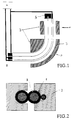
- FIG. 1 shows a schematic representation of the entire arrangement and FIG. 2 shows a cross section through a cable set with a compression mold.
- the cables 1 When the cables are welded, the cables 1 are first placed in shape 3 parallel to one another (see FIG. 1). Due to the cavities or grooves cut out in the mold 3, the individual cables are held together and positioned as soon as the pressure P is exerted on the mold and the individual molded parts are moved together. The cables are then connected to one another and to the power supply 4, as shown in FIG. 1.
- the insulation of the cable 2 is either in contact with the insulation of another cable or with the cooling liquid, provided that it is not cooled by the metallic form 2. Therefore, only the contact point of the insulation of the individual cables is heated and fused when the current passes through. After moving the molds together, the entire device (molds, lines, connections) is expediently lowered into a water bath.
- the cables are provided with cable lugs, for example, for connection to a car battery or to consumers. These cable lugs are connected to the power supply or to each other with shorting bars according to FIG. 1.
- the power supply unit delivers up to 1,000 A at 50 Hz. The current is passed through the cable until the insulation material melts at the points of contact. The remaining surface is cooled by oil or water so that the surface temperature does not reach the melting point of the insulation material.
- the particular advantage of this method is that the welding can be performed in one operation and the finished product takes a predetermined shape, for example a curve arc of 90 o permanent, so that the intended installation geometry can be taken into account already during the manufacture of the cable set.
- the method can be used for all cable insulation. There are no difficulties, for example, with PVC or rubber cores. Even with lines that are insulated with a polyimide, it is possible to reach the melting point and to weld the wires. In such a case, silicone oil is used as the coolant, for example.
- the welding of cores with polyamide insulation is an example here.
- the cores are inserted into the mold and pressed together with a force of 100 N / cm cable length.
- a pressure of approximately 1,000 N / cm2 is therefore required. If the temperature of the softening is increased, then of course one can manage with less pressure.
- the exact setting values must of course be determined experimentally in each individual case, but it is advantageous to use a higher pressure and a lower temperature so that the welding result is optimal.
Landscapes
- Engineering & Computer Science (AREA)
- Mechanical Engineering (AREA)
- Manufacturing & Machinery (AREA)
- Processing Of Terminals (AREA)
- Lining Or Joining Of Plastics Or The Like (AREA)
- Manufacturing Of Electrical Connectors (AREA)
Abstract
Bei einem Verfahren zum Verschweißen von Kabelisolierungen durch Erwärmung der Isolierungen, welche durch Druck zusammengepreßt werden, so daß die Kabelisolierungen miteinander verschmelzen, ist vorgesehen, daß die Kabelenden elektrisch verbunden werden und daß ein Strom durch die Kabel geleitet wird, so daß durch joulesche Wärme ein Verschmelzen der Kabelisolierungen erfolgt. <IMAGE>In a method for welding cable insulation by heating the insulation, which is pressed together by pressure so that the cable insulation fuses together, it is provided that the cable ends are electrically connected and that a current is passed through the cable, so that by Joule heat The cable insulation is melted. <IMAGE>
Description
Die Erfindung betrifft ein Verfahren zum Verschweißen von Isolierungen von Kabeln nach dem Oberbegriff des Anspruchs 1. Bisher war es üblich, Kabel, deren Isolierung verschweißt werden sollte, zu erhitzen und danach zu verpressen, so daß die Kunststoffmäntel an den Kontaktstellen verschweißten. Die Erhitzung der Kabelmäntel geschah beispielsweise durch das an sich bekannte Spiegelschweißverfahren.The invention relates to a method for welding insulation of cables according to the preamble of
Durch die separate Erhitzung der einzelnen Kabel wird die Fixierung der gegenseitigen Lage beim anschließenden Verpressen nicht sicher reproduziert. Es kann sehr leicht zu einer Beschädigung der Isolation kommen. Außerdem ist die Zeit zum Verpressen der Kabel begrenzt. Es besteht die Gefahr, daß beim Fixieren so viel Zeit verstreicht, daß sich die Kabelmäntel schon so stark abgekühlt haben, daß sich ein sicheres Verschweißen nicht gewährleistet ist.Due to the separate heating of the individual cables, the fixation of the mutual position during the subsequent crimping is not reliably reproduced. The insulation can easily be damaged. In addition, the time for crimping the cables is limited. There is a risk that so much time will elapse when fixing that the cable sheaths have already cooled down to such an extent that secure welding cannot be guaranteed.
Die Erfindung liegt daher die Aufgabe zugrunde, ein Verfahren der oben genannten Art anzugeben, bei dem die Kabel sicher positioniert werden können und ein reproduzierbares Schweißergebnis erzielt wird.The invention is therefore based on the object of specifying a method of the type mentioned above in which the cables can be securely positioned and a reproducible welding result is achieved.
Diese Aufgabe wird nach der Erfindung durch die im Kennzeichen des Anspruchs 1 aufgeführten Merkmale gelöst. Weiterbildungen der Erfindung sind in den Unteransprüchen aufgeführt. Anwendungen der Erfindung liegen u. a. auf dem Gebiet der Batteriekabelsätze in Kraftfahrzeugen.This object is achieved according to the invention by the features listed in the characterizing part of
Die Erfindung hat insbesondere den Vorteil, daß die so hergestellten Kabelsätze sehr formstabil sind. Außerdem bleiben die Kabelmäntel im Außenbereich praktisch undeformiert, da die entstehende joulesche Wärme nach außen durch eine Kühlvorrichtung abgeführt wird. Somit wird die Wärme nur an den Stellen wirksam, an denen eine Verschmelzung der Kabelmäntel erwünscht ist.The invention has the particular advantage that the cable sets produced in this way are very dimensionally stable. They also stay Cable sheaths practically undeformed in the outside area, since the resulting Joule heat is dissipated to the outside by a cooling device. This means that the heat is only effective at those points where a fusion of the cable sheaths is desired.
Die Erfindung wird nachstehend anhand der Zeichnung näher erläutert. Dabei zeigt Figur 1 eine schematische Darstellung der gesamten Anordnung und Figur 2 einen Querschnitt durch einen Kabelsatz mit Preßform.The invention is explained below with reference to the drawing. 1 shows a schematic representation of the entire arrangement and FIG. 2 shows a cross section through a cable set with a compression mold.
Beim Verschweißen der Kabel werden zunächst die Kabel 1 parallel zueinander in die Form 3 gelegt (siehe Figur 1). Durch die in der Form 3 ausgesparten Hohlräume oder Nuten werden die einzelnen Kabel zusammengehalten und positioniert, sobald der Preßdruck P auf auf die Form ausgeübt und die einzelnen Formteile zusammengefahren werden. Anschließend werden die Kabel, wie in Figur 1 gezeigt, miteinander und mit dem Netzgerät 4 verbunden.When the cables are welded, the
Die Isolierung der Kabel 2 steht entweder mit der Isolierung eines weiteren Kabels in Kontakt oder mit der Kühlflüssigkeit, soweit sie nicht von der metallischen Form 2 gekühlt wird. Deshalb wird beim Stromdurchgang nur die Berührungsstelle der Isolierung der einzelnen Kabel aufgeheizt und verschmilzt. Zweckmäßigerweise wird nach dem Zusammenfahren der Formen die gesamte Vorrichtung (Formen, Leitungen, Anschlüsse) in ein Wasserbad abgesenkt.The insulation of the
Die Kabel sind beispielsweise für den Anschluß an eine Autobatterie oder an Verbraucher mit Kabelschuhen versehen. Diese Kabelschuhe werden mit Kurzschlußbügeln gemäß Figur 1 mit dem Netzgerät oder untereinander verbunden. Das Netzgerät liefert beispielsweise bis zu 1.000 A bei 50 Hz. Der Strom wird solange durch das Kabel hindurchgeleitet, bis das Isolationsmaterial an den Berührungsstellen aufschmilzt. Die übrige Oberfläche wird durch Öl oder Wasser gekühlt, so daß hier die Oberflächentemperatur nicht den Schmelzpunkt des Isolationsmaterials erreicht.The cables are provided with cable lugs, for example, for connection to a car battery or to consumers. These cable lugs are connected to the power supply or to each other with shorting bars according to FIG. 1. For example, the power supply unit delivers up to 1,000 A at 50 Hz. The current is passed through the cable until the insulation material melts at the points of contact. The remaining surface is cooled by oil or water so that the surface temperature does not reach the melting point of the insulation material.
Der besondere Vorteil dieses Verfahrens besteht darin, daß die Schweißung in einem Arbeitsgang durchgeführt werden kann und das fertige Produkt eine vorgegebene Form, beispielsweise einen Kurvenbogen von 90 o dauerhaft einnimmt, so daß die vorgesehene Verlegegeometrie schon bei der Herstellung des Kabelsatzes berücksichtigt werden kann.The particular advantage of this method is that the welding can be performed in one operation and the finished product takes a predetermined shape, for example a curve arc of 90 o permanent, so that the intended installation geometry can be taken into account already during the manufacture of the cable set.
Das Verfahren ist bei allen Kabelisolierungen einsetzbar. Keinerlei Schwierigkeiten ergeben sich beispielsweise mit PVC- oder Gummiadern. Selbst bei Leitungen, welche mit einem Polyimid isoliert sind, ist es möglich, den Schmelzpunkt zu erreichen und die Adern zu verschweißen. Als Kühlmittel wird in einem solchen Fall beispielsweise Silikonöl eingesetzt.The method can be used for all cable insulation. There are no difficulties, for example, with PVC or rubber cores. Even with lines that are insulated with a polyimide, it is possible to reach the melting point and to weld the wires. In such a case, silicone oil is used as the coolant, for example.
Als Beispiel sei hier speziell das Verschweißen von Adern mit Isolation aus Polyamid genannt. Die Adern werden in die Form eingelegt und mit einer Kraft von 100 N/cm Kabellänge zusammengepreßt. Um die Isolierung auf einer Breite von 1 mm zusammenzupressen, ist daher ein Druck von etwa 1.000 N/cm² erforderlich. Wird die Temperatur der Erweichung erhöht, so kommt man natürlich mit geringerem Druck aus. Die exakten Einstellwerte müssen in jedem Einzelfall natürlich experimentell ermittelt werden, es ist jedoch vorteilhaft, einen höheren Druck und eine geringere Temperatur einzusetzen, damit das Schweißergebnis optimal wird.The welding of cores with polyamide insulation is an example here. The cores are inserted into the mold and pressed together with a force of 100 N / cm cable length. In order to compress the insulation to a width of 1 mm, a pressure of approximately 1,000 N / cm² is therefore required. If the temperature of the softening is increased, then of course one can manage with less pressure. The exact setting values must of course be determined experimentally in each individual case, but it is advantageous to use a higher pressure and a lower temperature so that the welding result is optimal.
Claims (9)
Applications Claiming Priority (2)
| Application Number | Priority Date | Filing Date | Title |
|---|---|---|---|
| DE19914101663 DE4101663C1 (en) | 1991-01-22 | 1991-01-22 | |
| DE4101663 | 1991-01-22 |
Publications (1)
| Publication Number | Publication Date |
|---|---|
| EP0496286A1 true EP0496286A1 (en) | 1992-07-29 |
Family
ID=6423411
Family Applications (1)
| Application Number | Title | Priority Date | Filing Date |
|---|---|---|---|
| EP19920100698 Withdrawn EP0496286A1 (en) | 1991-01-22 | 1992-01-17 | Method for welding cable insulations |
Country Status (11)
| Country | Link |
|---|---|
| US (1) | US5298101A (en) |
| EP (1) | EP0496286A1 (en) |
| JP (1) | JPH0594859A (en) |
| BR (1) | BR9200172A (en) |
| CA (1) | CA2059754A1 (en) |
| DE (1) | DE4101663C1 (en) |
| FI (1) | FI920260A (en) |
| HU (1) | HU207602B (en) |
| IE (1) | IE920171A1 (en) |
| NO (1) | NO920300L (en) |
| PT (1) | PT100046A (en) |
Families Citing this family (8)
| Publication number | Priority date | Publication date | Assignee | Title |
|---|---|---|---|---|
| DE19512113C2 (en) * | 1995-04-04 | 1997-12-18 | Gerhard Prof Dr Ing Babiel | Dimensionally stabilized battery cable |
| US5537742A (en) * | 1995-05-22 | 1996-07-23 | General Signal Corporation | Method for joining multiple conductor cables |
| IL116811A0 (en) * | 1996-01-18 | 1996-07-23 | Dan Pal Tech Plastic Ind | Structures made of panel units and connecting pieces and a method of forming such structures |
| US20050140065A1 (en) * | 2002-05-25 | 2005-06-30 | Hans-Martin Sauer | Method and device for connecting molded parts |
| US8404976B2 (en) * | 2009-01-30 | 2013-03-26 | Fort Wayne Metals Research Products Corporation | Fused wires |
| FR3026672B1 (en) * | 2014-10-02 | 2017-06-16 | Faurecia Bloc Avant | METHOD FOR MANUFACTURING A VEHICLE STRUCTURE HAVING TWO THERMOPLASTIC MATERIAL COMPONENTS FITTED BY HEATING, AND CORRESPONDING VEHICLE STRUCTURE |
| DE102015201711A1 (en) * | 2015-02-02 | 2016-08-04 | Bayerische Motoren Werke Aktiengesellschaft | Method for compacting individual wires |
| GB201802228D0 (en) * | 2018-02-12 | 2018-03-28 | Rolls Royce Plc | Cable harness |
Citations (2)
| Publication number | Priority date | Publication date | Assignee | Title |
|---|---|---|---|---|
| DE168457C (en) * | 1900-01-01 | |||
| US4430139A (en) * | 1978-08-15 | 1984-02-07 | Lucas Industries Limited | Apparatus for manufacturing cable |
Family Cites Families (2)
| Publication number | Priority date | Publication date | Assignee | Title |
|---|---|---|---|---|
| US2425294A (en) * | 1944-12-18 | 1947-08-12 | John T Morgan | Method of making insulated multiconductor structures |
| US2489867A (en) * | 1946-06-13 | 1949-11-29 | Belmont Radio Corp | Method for making electrical coils |
-
1991
- 1991-01-22 DE DE19914101663 patent/DE4101663C1/de not_active Expired - Lifetime
-
1992
- 1992-01-16 JP JP4246192A patent/JPH0594859A/en active Pending
- 1992-01-17 EP EP19920100698 patent/EP0496286A1/en not_active Withdrawn
- 1992-01-21 IE IE017192A patent/IE920171A1/en not_active Application Discontinuation
- 1992-01-21 US US07/823,537 patent/US5298101A/en not_active Expired - Fee Related
- 1992-01-21 FI FI920260A patent/FI920260A/en unknown
- 1992-01-21 BR BR9200172A patent/BR9200172A/en unknown
- 1992-01-21 HU HU9200189A patent/HU207602B/en not_active IP Right Cessation
- 1992-01-22 PT PT100046A patent/PT100046A/en not_active Application Discontinuation
- 1992-01-22 NO NO92920300A patent/NO920300L/en unknown
- 1992-01-22 CA CA 2059754 patent/CA2059754A1/en not_active Abandoned
Patent Citations (2)
| Publication number | Priority date | Publication date | Assignee | Title |
|---|---|---|---|---|
| DE168457C (en) * | 1900-01-01 | |||
| US4430139A (en) * | 1978-08-15 | 1984-02-07 | Lucas Industries Limited | Apparatus for manufacturing cable |
Also Published As
| Publication number | Publication date |
|---|---|
| HU207602B (en) | 1993-04-28 |
| NO920300D0 (en) | 1992-01-22 |
| IE920171A1 (en) | 1992-07-29 |
| HU9200189D0 (en) | 1992-04-28 |
| PT100046A (en) | 1994-04-29 |
| HUT60069A (en) | 1992-07-28 |
| US5298101A (en) | 1994-03-29 |
| BR9200172A (en) | 1992-10-06 |
| FI920260A (en) | 1992-07-23 |
| DE4101663C1 (en) | 1992-03-12 |
| CA2059754A1 (en) | 1992-07-23 |
| JPH0594859A (en) | 1993-04-16 |
| FI920260A0 (en) | 1992-01-21 |
| NO920300L (en) | 1992-07-23 |
Similar Documents
| Publication | Publication Date | Title |
|---|---|---|
| EP0022919B1 (en) | Method for the impregnation of tissues by resin injection | |
| DE2739021C2 (en) | ||
| DE60022438T2 (en) | Apparatus and method for heating the protective jacket of a fiber splice | |
| DE69726468T2 (en) | Device and method for connecting by melting a pipe with coupling pieces | |
| DE1565888A1 (en) | Self-regulating radiator and process for its manufacture | |
| DE8390057U1 (en) | Connector with fusible material and its own temperature control | |
| EP3417513B1 (en) | Method and device for sealing contact points at electrical line connections | |
| DE60029120T2 (en) | HEATING DEVICE WITH A FORMABLE INDUCTION GRINDING AND METHOD FOR ACCELERATED HARDENING OF THE CONNECTED PARTS | |
| DE3883797T2 (en) | Electro fusion welding of thermoplastic materials. | |
| EP0496286A1 (en) | Method for welding cable insulations | |
| EP3609023B1 (en) | Method and device for making an electrical connection and an electrical line | |
| DE102017008496B4 (en) | Method of manufacturing a heating element for user-touchable surfaces in a vehicle | |
| DE69801051T2 (en) | DEVICE CONNECTING DEVICE | |
| EP1065037B1 (en) | Process of and apparatus for heating of injection moulds | |
| DE102012212202A1 (en) | Method for connecting workpieces and connecting device | |
| DE102015117020B4 (en) | Method for producing a line seal of a line harness and method for producing a sealed line connection | |
| DE2646233A1 (en) | WELDING MACHINE | |
| DE102014017922B4 (en) | Method for the component connection of a plastic component with a joining partner | |
| DE2739418C2 (en) | Method for producing a contact connection between an enamel-insulated wire and a contact part of an electrical component by means of soft soldering and a device for carrying out the method | |
| DE69203175T2 (en) | Process for the production of stranded wires for electromechanical device technology and device for carrying out the process. | |
| DE10342964A1 (en) | Flat wire repair tool systems and processes | |
| DE68913534T2 (en) | METHOD AND DEVICE USING CONDUCTIVE POLYMERS FOR CONNECTING OBJECTS. | |
| DE69611362T2 (en) | METHOD FOR SEALING A CABLE OR LADDER | |
| DE102016121909B4 (en) | Sealing of line connectors | |
| DE1919973A1 (en) | Electrical device, especially spark gap, and methods and devices for its manufacture |
Legal Events
| Date | Code | Title | Description |
|---|---|---|---|
| PUAI | Public reference made under article 153(3) epc to a published international application that has entered the european phase |
Free format text: ORIGINAL CODE: 0009012 |
|
| AK | Designated contracting states |
Kind code of ref document: A1 Designated state(s): AT BE CH DE DK ES FR GB GR IT LI LU NL SE |
|
| 17P | Request for examination filed |
Effective date: 19920721 |
|
| 17Q | First examination report despatched |
Effective date: 19940614 |
|
| STAA | Information on the status of an ep patent application or granted ep patent |
Free format text: STATUS: THE APPLICATION IS DEEMED TO BE WITHDRAWN |
|
| 18D | Application deemed to be withdrawn |
Effective date: 19941017 |