EP0496197B1 - Flanged joint, especially for motor vehicle drive shafts - Google Patents
Flanged joint, especially for motor vehicle drive shafts Download PDFInfo
- Publication number
- EP0496197B1 EP0496197B1 EP92100096A EP92100096A EP0496197B1 EP 0496197 B1 EP0496197 B1 EP 0496197B1 EP 92100096 A EP92100096 A EP 92100096A EP 92100096 A EP92100096 A EP 92100096A EP 0496197 B1 EP0496197 B1 EP 0496197B1
- Authority
- EP
- European Patent Office
- Prior art keywords
- wedge
- flanges
- keyways
- shaped
- flange connection
- Prior art date
- Legal status (The legal status is an assumption and is not a legal conclusion. Google has not performed a legal analysis and makes no representation as to the accuracy of the status listed.)
- Expired - Lifetime
Links
- 241000397426 Centroberyx lineatus Species 0.000 claims 1
- 230000002401 inhibitory effect Effects 0.000 claims 1
- 230000005540 biological transmission Effects 0.000 description 4
- 210000000078 claw Anatomy 0.000 description 3
- 239000002184 metal Substances 0.000 description 3
- 238000010276 construction Methods 0.000 description 2
- 230000002349 favourable effect Effects 0.000 description 2
- 241001290076 Papilio machaon Species 0.000 description 1
- 238000004026 adhesive bonding Methods 0.000 description 1
- 238000010438 heat treatment Methods 0.000 description 1
- 238000009434 installation Methods 0.000 description 1
- 230000002093 peripheral effect Effects 0.000 description 1
- 238000003466 welding Methods 0.000 description 1
Images


Classifications
-
- F—MECHANICAL ENGINEERING; LIGHTING; HEATING; WEAPONS; BLASTING
- F16—ENGINEERING ELEMENTS AND UNITS; GENERAL MEASURES FOR PRODUCING AND MAINTAINING EFFECTIVE FUNCTIONING OF MACHINES OR INSTALLATIONS; THERMAL INSULATION IN GENERAL
- F16D—COUPLINGS FOR TRANSMITTING ROTATION; CLUTCHES; BRAKES
- F16D1/00—Couplings for rigidly connecting two coaxial shafts or other movable machine elements
- F16D1/06—Couplings for rigidly connecting two coaxial shafts or other movable machine elements for attachment of a member on a shaft or on a shaft-end
- F16D1/076—Couplings for rigidly connecting two coaxial shafts or other movable machine elements for attachment of a member on a shaft or on a shaft-end by clamping together two faces perpendicular to the axis of rotation, e.g. with bolted flanges
-
- F—MECHANICAL ENGINEERING; LIGHTING; HEATING; WEAPONS; BLASTING
- F16—ENGINEERING ELEMENTS AND UNITS; GENERAL MEASURES FOR PRODUCING AND MAINTAINING EFFECTIVE FUNCTIONING OF MACHINES OR INSTALLATIONS; THERMAL INSULATION IN GENERAL
- F16B—DEVICES FOR FASTENING OR SECURING CONSTRUCTIONAL ELEMENTS OR MACHINE PARTS TOGETHER, e.g. NAILS, BOLTS, CIRCLIPS, CLAMPS, CLIPS OR WEDGES; JOINTS OR JOINTING
- F16B3/00—Key-type connections; Keys
-
- F—MECHANICAL ENGINEERING; LIGHTING; HEATING; WEAPONS; BLASTING
- F16—ENGINEERING ELEMENTS AND UNITS; GENERAL MEASURES FOR PRODUCING AND MAINTAINING EFFECTIVE FUNCTIONING OF MACHINES OR INSTALLATIONS; THERMAL INSULATION IN GENERAL
- F16D—COUPLINGS FOR TRANSMITTING ROTATION; CLUTCHES; BRAKES
- F16D3/00—Yielding couplings, i.e. with means permitting movement between the connected parts during the drive
- F16D3/16—Universal joints in which flexibility is produced by means of pivots or sliding or rolling connecting parts
- F16D3/26—Hooke's joints or other joints with an equivalent intermediate member to which each coupling part is pivotally or slidably connected
- F16D3/38—Hooke's joints or other joints with an equivalent intermediate member to which each coupling part is pivotally or slidably connected with a single intermediate member with trunnions or bearings arranged on two axes perpendicular to one another
- F16D3/382—Hooke's joints or other joints with an equivalent intermediate member to which each coupling part is pivotally or slidably connected with a single intermediate member with trunnions or bearings arranged on two axes perpendicular to one another constructional details of other than the intermediate member
- F16D3/387—Fork construction; Mounting of fork on shaft; Adapting shaft for mounting of fork
Definitions
- the invention relates to a flange connection for connecting two shaft flanges, in particular in motor vehicle drives, which are provided with end-face toothing for torque transmission and are held axially clamped against one another by means of clamping means, the clamping means having corresponding wedge surfaces attached to the flanges to be connected and lying opposite one another with contact surfaces which are located on one another extend wedge-shaped from each other, and wherein the tensioning means have connecting means which are designed to achieve an operative connection with the contact surfaces and act on them.
- Such a flange connection results from US-A-2 303 031. Thereafter, it is further provided to provide two shafts at their mutually facing ends with thickened areas which have inclined surfaces which approach each other radially outwards and are designed as conical surfaces. The wedge surfaces run around the shaft.
- a multiply divided ring is attached from the outside, which has corresponding surfaces, engages over both shaft sections and braces them against one another. Screws are used to brace the circular ring sections of the divided ring against one another.
- the wedges are secured against falling out by a screwed-on sleeve.
- the wedges transmit the torque between the two flanges.
- the connection is therefore subject to play both in the axial direction and in the direction of rotation. This can cause the connection to reject.
- WO-A87 / 07073 describes an ignition coil in which the core assembled from sheet metal lamellae is held together by a metal clip.
- the sheet metal lamellae each have two spaced bores which are connected by a slot.
- the clip has two pins connected by a web. The connection is achieved by inserting the clamp and a conical tightening.
- Flange connections are used, for example, in motor vehicle construction in order to driveally drive universal joint shafts, which are provided with driver flanges at the end, with corresponding counter flanges in the motor vehicle.
- Such connections are generally made by screwing. Due to the increasingly compact design, however, the accessibility of screws is becoming more and more restricted. In addition, such screw connections are not suitable for automating assembly.
- the object of the present invention is to provide a flange connection of the type described at the outset, which is simple in its construction and enables an easily accessible quick connection between shaft flanges.
- the contact surfaces of the wedge surfaces are formed by wedge-shaped wedge-shaped grooves, that the wedge-shaped grooves each form a pair whose longitudinal axis is tangential to the axis of rotation, the wedge grooves running symmetrically to the longitudinal axis and approaching this in that the connecting means are designed as connecting wedges or wedge-shaped brackets and that the connecting means are secured in the clamped position.
- This measure creates a screw-free connection between two flanges, which enables quick fastening and allows lateral accessibility when mounted on the motor vehicle.
- a flange connection can be pretensioned and can be preassembled by hand using simple means.
- the flanges to be connected to each other are on the front provided with toothings for torque transmission so that the connection is torque-free. This enables a very direct power transmission from the bearing to the counter flanges. Short overall lengths and high rigidity are also achieved.
- the cross toothing on the end faces of the flanges to be connected can be placed in an area which is favorable for the flow of force and unbalances can be reduced.
- the opposing splines are part of lateral spline guides which are provided with opposing contact surfaces as the spline surfaces.
- lateral wedge guides each have a double T, dovetail or club shape in cross section.
- the flanges to be connected to one another are peripherally provided with lateral collars which have the mutually directed splines, and that the flanges can be braced against one another by means of wedge-shaped, cross-sectionally C-shaped clamps.
- Two wedge surfaces are preferably arranged in pairs running diametrically.
- the propeller shaft 10 shown in Figure 1 consists essentially of a first shaft part 11 and a second shaft part 12.
- the second shaft part 12 has a compensating sleeve 13 in which the profiled pin 14 is slidably but rotatably received to form a length compensation.
- the shaft parts 11 and 12 are provided with joint forks 15a of universal joints 16.
- the articulated forks 15a of the universal joints 16 are connected in an articulated manner to the articulated forks 15 at the ends via a trunnion cross.
- the articulated forks 15 are part of connecting flanges 17 which have end-face toothing 18 for torque transmission and are intended for connection to counter flanges.
- the connecting flanges 17 can be connected via the toothing 18 to correspondingly designed counter flanges 19, the counter flanges 19 in turn being connectable to an input or output shaft 20.
- the connecting flange 17 is provided with splines 21 which run tangentially to the axis of rotation 23 and the counter flange 19 is also provided with splines 21a which also run tangentially to the axis of rotation 23.
- the splines 21 and 21a are each T-shaped in cross-section and, through their corresponding arrangement, form a double T-shape.
- 19 connecting wedges 22 can be inserted into the formed keyways 21, 21a for connecting the connecting flange 17 to the counter flange 19.
- the keyways 21 and 21a are formed in pairs and run on both sides of the axis of rotation 23 with their longitudinal axis 35 tangential to it.
- the keyways 21, 21a are formed symmetrically with respect to their longitudinal axis 35, whereby they approach the longitudinal axis 35. Furthermore, they are provided with undercut wedge guides 24 on the side.
- the wedge guides 24 form pressure surfaces 25 directed towards one another in the direction of the axis of rotation 23 for receiving lateral wedge webs 28 of the connecting wedges to be used 22.
- the splines 21, 21a open toward the opening side 26 with the spline angle 27.
- the splines 21, 21a, as shown in FIG. 6, can be provided with dovetails 33 on both ends in cross section. In another embodiment, as shown in FIG. 7, the ends of a keyway 21 are designed as lobes 34.
- the assembly connection of the two connecting flanges 17, 19 takes place in such a way that they are brought closer together along the axis of rotation 23 until the connecting wedge 22 with its largest opening cross section between the wedge webs 28 can be inserted into the wedge guide 24, starting from the opening side opposite the opening side 26.
- the connecting wedge 22 is pushed in further in the direction of the opening side 26, the flanges 17, 19 approach one another until they are braced together.
- the connecting wedges 22 attached in the center of the radial extension of the toothing 18 bring about a particularly favorable bracing by distributing the clamping forces.
- the connecting flange 17 and the counter flange 19 are provided with wedge-shaped collars 31 which extend in a tangential direction.
- These laterally tangential collars 31 have projections 32, by means of which splines 30 tangential on the counter flange 19 and splines 30 a tangential on the connecting flange 17 are formed, the splines 30, 30 a moving away from the connecting plane of the flanges 17, 19.
- wedge-shaped clamps 29 can be pushed over the collars.
- the brackets 29 are C-shaped in cross section trained so that the collars 31 are overlapped from the outside.
- the wedge-shaped clamps 29 come into operative connection with the wedge-shaped keyways 30, 30a and hold the flanges 17 and 19 firmly against one another by their pretensioning. To secure the wedge-shaped clamps 29, these can also be fixed on their opening sides by caulking, welding or gluing to the flanges 17, 19. These wedge-shaped clamps 29 are, as shown in FIG. 5, symmetrical to their longitudinal axes 35.
- the keyways 30, 30a are tangent to the axis of rotation 23 and are arranged such that their contact surfaces 25 lie radially within the radial bearing bush contour in the flange driver.
Landscapes
- Engineering & Computer Science (AREA)
- General Engineering & Computer Science (AREA)
- Mechanical Engineering (AREA)
- Motor Power Transmission Devices (AREA)
- Clamps And Clips (AREA)
- Arrangement And Driving Of Transmission Devices (AREA)
- Snaps, Bayonet Connections, Set Pins, And Snap Rings (AREA)
- Mutual Connection Of Rods And Tubes (AREA)
Abstract
Description
Die Erfindung betrifft eine Flanschverbindung zur Verbindung zweier Wellenflansche, insbesondere in Kraftfahrzeugantrieben, die mit stirnseitigen Verzahnungen zur Drehmomentübertragung versehen und über Spannmittel axial gegeneinander verspannt gehalten sind, wobei die Spannmittel an den zu verbindenden Flanschen angebrachte und einander gegenüberliegende korrespondierende Keilflächen mit Anpreßflächen aufweisen, welche sich voneinander keilförmig entfernend verlaufen, und wobei die Spannmittel Verbindungsmittel aufweisen, die zur Erzielung einer Wirkverbindung mit den Anpreßflächen entsprechend gestaltet sind und an diesen angreifen.The invention relates to a flange connection for connecting two shaft flanges, in particular in motor vehicle drives, which are provided with end-face toothing for torque transmission and are held axially clamped against one another by means of clamping means, the clamping means having corresponding wedge surfaces attached to the flanges to be connected and lying opposite one another with contact surfaces which are located on one another extend wedge-shaped from each other, and wherein the tensioning means have connecting means which are designed to achieve an operative connection with the contact surfaces and act on them.
Eine solche Flanschverbindung ergibt sich aus der US-A-2 303 031. Danach ist es ferner vorgesehen, zwei Wellen an ihren einander zugewandten Enden mit Verdickungen zu versehen, die Schrägflächen aufweisen, die sich radial nach außen einander annähern und als Kegelflächen gestaltet sind. Die Keilflächen verlaufen um die Welle herum. Von außen ist ein mehrfach geteilter Ring aufgesetzt, der entsprechende Flächen aufweist, beide Wellenabschnitte übergreift und diese gegeneinander verspannt. Zur Verspannung der Kreisringabschnitte des geteilten Ringes gegeneinander dienen Schrauben.Such a flange connection results from US-A-2 303 031. Thereafter, it is further provided to provide two shafts at their mutually facing ends with thickened areas which have inclined surfaces which approach each other radially outwards and are designed as conical surfaces. The wedge surfaces run around the shaft. A multiply divided ring is attached from the outside, which has corresponding surfaces, engages over both shaft sections and braces them against one another. Screws are used to brace the circular ring sections of the divided ring against one another.
In der DE C 35 31 822 ist eine Flanschverbindung mit kegelförmigen Verbindungsmitteln beschrieben, welche lediglich dafür sorgen, daß die beiden Flansche axial zueinander gehalten werden. Ein axiales Verspannen der Verzahnungen der Flansche gegeneinander ist nicht möglich.DE C 35 31 822 describes a flange connection with conical connecting means which merely ensure that the two flanges are held axially to each other. Axial tensioning of the teeth of the flanges against one another is not possible.
Aus der GB-A-8470 / 1911 ist es bekannt, in die gegenüberliegenden Stirnflächen von zwei Flanschen ausgehend von den Stirnflächen hinterschnittene Nuten einzuarbeiten. Die Nuten kreuzen die Drehachse der Flansche mit Abstand und sind zu den Außenumfangsflächen der Flansche offen. Die sich gegenüberliegenden Nuten sind im Querschnitt schwalbenschwanzförmig gestaltet. Der Querschnitt der Nuten bleibt über deren Länge konstant. In jeweils zwei gegenüberliegenden Nuten ist ein gemeinsamer Keil eingeschoben, der die beiden Flansche axial miteinander verbindet.From GB-A-8470/1911 it is known to incorporate undercut grooves in the opposite end faces of two flanges starting from the end faces. The grooves cross the axis of rotation of the flanges at a distance and are open to the outer peripheral surfaces of the flanges. The opposite grooves are dovetail-shaped in cross section. The cross section of the grooves remains constant over their length. A common wedge is inserted into two opposite grooves, which axially connects the two flanges.
Die Keile sind gegen Herausfallen durch eine aufgeschraubte Hülse gesichert. Die Keile übertragen das Drehmoment zwischen den beiden Flanschen. Damit ist die Verbindung sowohl in Axialrichtung als auch in Drehrichtung spielbehaftet. Dies kann zu einem Ausschlagen der Verbindung führen.The wedges are secured against falling out by a screwed-on sleeve. The wedges transmit the torque between the two flanges. The connection is therefore subject to play both in the axial direction and in the direction of rotation. This can cause the connection to reject.
In der WO-A87/07073 ist eine Zündspule beschrieben, bei der der aus Blechlamellen zusammengefügte Kern durch eine metallene Klammer zusammengehalten wird. Dazu weisen die Blechlamellen jeweils zwei beabstandete Bohrungen auf, die durch einen Schlitz verbunden sind. Die Klammer hat zwei durch einen Steg verbundene Stifte. Die Verbindung wird durch Einschieben der Klammer und einen konischen Anzug erreicht.WO-A87 / 07073 describes an ignition coil in which the core assembled from sheet metal lamellae is held together by a metal clip. For this purpose, the sheet metal lamellae each have two spaced bores which are connected by a slot. The clip has two pins connected by a web. The connection is achieved by inserting the clamp and a conical tightening.
Aus der DE -U- 87 15 364 ist es bekannt, die Peripherie von miteinander zu verbindenden Flanschen durch zwei gegeneinander gerichtete teiltorusförmige Schalen, die wiederum zu einem Torus zusammensetzbar sind, miteinander zu verbinden. Für eine derartige Flanschverbindung wird jedoch ein vergrößerter radialer Bauraum benötigt, der in Fahrzeugen nicht zur Verfügung steht. Außerdem bedeutet ein derartiger Torus eine zusätzlich rotierende Masse, die bei den zu erwartenden hohen Drehzahlen zu Unwuchten führen kann.From DE -U- 87 15 364 it is known to connect the periphery of flanges to be connected to one another by means of two oppositely directed part-toroidal shells, which in turn can be assembled into a torus. However, an enlarged radial installation space is required for such a flange connection, which is not available in vehicles. In addition, such a torus means an additional rotating mass, which can lead to imbalances at the high speeds to be expected.
Aus der DE -A- 31 49 156 A1 ist es bekannt, die Flansche einer Flanschverbindung mit Bunden zu versehen, auf die Spannklauen aufgeschrumpft werden. Auch derartige Spannklauen bedeuten einerseits eine Vergrößerung der rotierenden Massen, andererseits bedeutet das Aufschrumpfen der Spannklauen einen erheblichen Energieaufwand für die Erwärmung und Montageaufwand.From DE -A- 31 49 156 A1 it is known to provide the flanges of a flange connection with collars onto which the clamping claws are shrunk. Clamping claws of this type also mean, on the one hand, an increase in the rotating masses, and, on the other hand, the shrinking of the clamping claws means a considerable expenditure of energy for heating and assembly.
Flanschverbindungen werden beispielsweise im Kraftfahrzeugbau dazu eingesetzt, um Kreuzgelenkwellen, die endseitig mit Mitnehmerflanschen versehen sind, mit entsprechenden Gegenflanschen im Kraftfahrzeug antriebsmäßig zu verbinden. Derartige Verbindungen werden allgemein durch Verschrauben hergestellt. Durch die immer kompakter werdende Bauweise wird jedoch die Zugänglichkeit von Schrauben mehr und mehr beschränkt. Außerdem eignen sich derartige Verschraubungen nicht für eine Automatisierung der Montage.Flange connections are used, for example, in motor vehicle construction in order to driveally drive universal joint shafts, which are provided with driver flanges at the end, with corresponding counter flanges in the motor vehicle. Such connections are generally made by screwing. Due to the increasingly compact design, however, the accessibility of screws is becoming more and more restricted. In addition, such screw connections are not suitable for automating assembly.
Aufgabe der vorliegenden Erfindung ist es, eine Flanschverbindung der eingangs beschriebenen Art zu schaffen, die einfach in ihrem Aufbau ist und eine leicht zugängliche Schnellverbindung zwischen Wellenflanschen ermöglicht.The object of the present invention is to provide a flange connection of the type described at the outset, which is simple in its construction and enables an easily accessible quick connection between shaft flanges.
Diese Aufgabe wird erfindungsgemäß dadurch gelöst, daß die Anpreßflächen der Keilflächen von sich keilförmig entfernenden Keilnuten gebildet sind, daß die Keilnuten jeweils ein Paar bilden, dessen Längsachse tangential zur Rotationsachse verläuft, wobei die Keilnuten symmetrisch zur Längsachse verlaufen und sich dieser annähern, daß die Verbindungsmittel als Verbindungskeile oder keilförmige Klammern ausgebildet sind und daß die Verbindungsmittel in der verspannten Position gesichert sind.This object is achieved in that the contact surfaces of the wedge surfaces are formed by wedge-shaped wedge-shaped grooves, that the wedge-shaped grooves each form a pair whose longitudinal axis is tangential to the axis of rotation, the wedge grooves running symmetrically to the longitudinal axis and approaching this in that the connecting means are designed as connecting wedges or wedge-shaped brackets and that the connecting means are secured in the clamped position.
Durch diese Maßnahme wird eine verschraubungsfreie Verbindung zwischen zwei Flanschen geschaffen, die eine Schnellbefestigung ermöglicht und bei der Montage am Kraftfahrzeug eine seitliche Zugänglichkeit ermöglicht. Eine derartige Flanschverbindung ist vorspannbar und kann mit einfachen Mitteln von Hand vormontiert werden. Die miteinander zu verbindenden Flansche sind stirnseitig mit Verzahnungen zur Drehmomentübertragung versehen, so daß die Verbindung drehmomentfrei ist. Dadurch wird eine sehr direkte Kraftübertragung von der Lagerung bis zu den Gegenflanschen möglich. Es werden dadurch ferner kurze Baulängen und eine hohe Steifigkeit erreicht. Die Kreuzverzahnung an den Stirnseiten der zu verbindenden Flansche kann in einen für den Kraftfluß güngstigen Bereich gelegt werden und es lassen sich Unwuchten verringern.This measure creates a screw-free connection between two flanges, which enables quick fastening and allows lateral accessibility when mounted on the motor vehicle. Such a flange connection can be pretensioned and can be preassembled by hand using simple means. The flanges to be connected to each other are on the front provided with toothings for torque transmission so that the connection is torque-free. This enables a very direct power transmission from the bearing to the counter flanges. Short overall lengths and high rigidity are also achieved. The cross toothing on the end faces of the flanges to be connected can be placed in an area which is favorable for the flow of force and unbalances can be reduced.
Bei einer bevorzugten Ausführungsform ist es vorgesehen, daß die einander gegenüberliegenden Keilnuten Bestandteil von seitlichen Keilführungen sind, die mit gegeneinandergerichteten Anpreßflächen als Keilflächen versehen sind.In a preferred embodiment it is provided that the opposing splines are part of lateral spline guides which are provided with opposing contact surfaces as the spline surfaces.
Ferner ist vorgesehen, daß die seitlichen Keilführungen im Querschnitt zusammen jeweils eine doppelte T-, Schwalbenschwanzoder Keulenform aufweisen.It is further provided that the lateral wedge guides each have a double T, dovetail or club shape in cross section.
Bei einer anderen Ausführungsform ist vorgesehen, daß die miteinander zu verbindenden Flansche peripher mit seitlichen Bunden versehen sind, die die gegeneinander gerichteten Keilnuten aufweisen, und daß die Flansche durch keilförmige, im Querschnitt C-förmige Klammern gegeneinander verspannbar sind.In another embodiment it is provided that the flanges to be connected to one another are peripherally provided with lateral collars which have the mutually directed splines, and that the flanges can be braced against one another by means of wedge-shaped, cross-sectionally C-shaped clamps.
Vorzugsweise sind jeweils zwei Keilflächen paarweise diametral verlaufend angeordnet.Two wedge surfaces are preferably arranged in pairs running diametrically.
Zur Sicherung der Flanschverbindung ist es vorgesehen, die keilförmigen Verbindungsmittel durch Kraftschluß selbsthemmend zu den Keilflächen in Wirkverbindung zu halten, bzw. die keilförmigen Verbindungsmittel durch Verpressen oder Verzahnung formschlüssig zu den Keilflächen in Wirkverbindung zu halten.To secure the flange connection, it is provided to hold the wedge-shaped connecting means in operative connection with the wedge-shaped surfaces in a self-locking manner, or to keep the wedge-shaped connecting means in operative connection with the wedge-shaped surfaces by pressing or toothing.
Die Erfindung ist anhand von zwei Ausführungsbeispielen in der beiliegenden Zeichnung dargestellt und wird nachfolgend näher beschrieben.The invention is illustrated by means of two exemplary embodiments in the accompanying drawing and is described in more detail below.
Es zeigt
- Figur 1
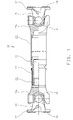
- die Längsansicht, teilweise geschnitten, einer längenveränderbaren Kreuzgelenkwelle, die beidendig mit Anschlußflanschen zur Verbindung mit Gegenflanschen versehen ist,
- Figur 2
- eine Detaildarstellung der Verbindung zwischen einem gelenkwellenseitigen Anschlußflansch und einem Gegenflansch, mit tangential verlaufenden T-förmig ausgebildeten Verbindungsmitteln;
- Figur 3
- einen Schnitt entsprechend der Linie III-III von Figur 2 durch die Verbindungsmittel;
- Figur 4
- eine Verbindung zwischen einem gelenkwellenseitigen Anschlußflansch und einem Gegenflansch durch tangential verlaufende seitliche Bunde, die von keilförmigen Klammern übergriffen sind;
- Figur 5
- eine Seitenansicht der Flanschverbindung nach der Figur 4;
- Figur 6
- einen Innenkeilquerschnitt für die keilförmigen Verbindungsmittel nach den Figuren 2 und 3 als Schwalbenschwanz;
- Figur 7
- einen Innenkeilquerschnitt für die keilförmigen Verbindungsmittel nach den Figuren 2 und 3 als Keulenform.
- Figure 1
- the longitudinal view, partly in section, of a variable-length universal joint shaft, which is provided at both ends with connecting flanges for connection to counter flanges,
- Figure 2
- a detailed view of the connection between a joint-flange connection flange and a counter-flange, with tangentially running T-shaped connecting means;
- Figure 3
- a section along the line III-III of Figure 2 by the connecting means;
- Figure 4
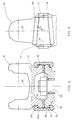
- a connection between a connecting flange on the drive shaft side and a counter flange by tangential lateral collars which are overlapped by wedge-shaped clamps;
- Figure 5
- a side view of the flange connection of Figure 4;
- Figure 6
- an inner wedge cross-section for the wedge-shaped connecting means according to Figures 2 and 3 as a dovetail;
- Figure 7
- an inner wedge cross section for the wedge-shaped connecting means according to Figures 2 and 3 as a club shape.
Die in der Figur 1 dargestellte Gelenkwelle 10 besteht im wesentlichen aus einem ersten Wellenteil 11 und einem zweiten Wellenteil 12. Das zweite Wellenteil 12 weist eine Ausgleichshülse 13 auf, in der der profilierte Zapfen 14 zur Bildung eines Längenausgleichs verschiebbar, aber drehfest aufgenommen ist. Endseitig sind die Wellenteile 11 und 12 mit Gelenkgabeln 15a von Kreuzgelenken 16 versehen. Die Gelenkgabeln 15a der Kreuzgelenke 16 sind über jeweils ein Zapfenkreuz gelenkig mit den endseitigen Gelenkgabeln 15 verbunden. Die Gelenkgabeln 15 sind Bestandteil von Anschlußflanschen 17, die stirnseitige Verzahnungen 18 zur Drehmomentübertragung aufweisen und zur Verbindung mit Gegenflanschen gedacht sind.The
Wie die Figur 2 zeigt, können die Anschlußflansche 17 über die Verzahnungen 18 mit entprechend ausgebildeten Gegenflanschen 19 verbunden werden, wobei die Gegenflansche 19 widerum mit einer An- oder Abtriebswelle 20 verbindbar sind.As FIG. 2 shows, the connecting
Wie aus Figur 2 und 3 ersichtlich, ist zur Verbindung der Anschlußflansch 17 mit tangential zur Rotationsachse 23 verlaufenden Keilnuten 21 und der Gegenflansch 19 mit ebenfalls tangential zur Rotationsachse 23 verlaufenden Keilnuten 21a versehen. Die Keilnuten 21 und 21a sind im Querschnitt jeweils T-förmig ausgebildet und bilden durch ihre korrespondierende Anordnung eine doppelte T-Form. In die ausgebildeten Keilnuten 21,21a können zur Verbindung des Anschlußflansches 17 mit dem Gegenflansch 19 Verbindungskeile 22 eingelegt werden. Die Keilnuten 21 und 21a sind paarweise ausgebildet und verlaufen beiderseits der Rotationsachse 23 mit ihrer Längsachse 35 tangential zu dieser. Die Keilnuten 21,21a sind symmetrisch zu ihrer Längsachse 35 ausgebildet, wobei sie sich der Längsachse 35 annähern. Ferner sind sie mit seitlich hinterschnittenen Keilführungen 24 versehen. Die Keilführungen 24 bilden in Richtung der Rotationsachse 23 gegeneinandergerichtete Anpreßflächen 25 zur Aufnahme von seitlichen Keilstegen 28 der einzusetzenden Verbindungskeile 22.Die Keilnuten 21,21a öffnen sich zur Öffnungsseite 26 hin mit dem Keilwinkel 27. Die Keilnuten 21,21a können, wie in der Figur 6 dargestellt ist, im Querschnitt beidendig mit Schwalbenschwänzen 33 versehen sein. Bei einer anderen Ausführung, wie sie in der Figur 7 dargestellt ist, sind die Enden einer Keilnut 21 als Keulen 34 ausgebildet. Die Montageverbindung der beiden Anschlußflansche 17,19 erfolgt derart, daß diese entlang der Rotationsachse 23 aneinanderangenähert werden, bis der Verbindungskeil 22 mit seinem größten Öffnungsquerschnitt zwischen den Keilstegen 28 in die Keilführung 24, ausgehend von der der Öffnungsseite 26 gegenüberliegenden Öffnungsseite, eingeschoben werden kann. Beim weiteren Einschieben des Verbindungskeils 22 in Richtung der Öffnungsseite 26 nähern sich die Flansche 17,19 bis zum gegenseitigen Verspannen an. Alternativ ist es jedoch möglich, die Nutenform der Keilführungen 24 so zu gestalten, daß der Verbindungskeil 22 bei aneinanderliegenden Flanschen 17,19 eingeführt werden kann. Die mittig der radialen Erstreckung der Verzahnung 18 angebrachten Verbindungskeile 22 bewirken eine besonders günstige Verspannung durch Verteilung der Spannkräfte.As can be seen from FIGS. 2 and 3, the connecting
Bei einer anderen Ausführungsform, wie sie in den Figuren 4 und 5 dargestellt ist, sind der Anschlußflansch 17 und der Gegenflansch 19 mit peripher tangential verlaufenden keilförmigen Bunden 31 versehen. Diese seitlich tangential verlaufenden Bunde 31 weisen Vorsprünge 32 auf, durch die an dem Gegenflansch 19 tangential verlaufende Keilnuten 30 und an dem Anschlußflansch 17 tangential verlaufende Keilnuten 30a gebildet werden, wobei die Keilnuten 30,30a sich von der Anschlußebene der Flansche 17,19 entfernen. Zur Verbindung der Flansche 17 und 19 können über die Bunde 31 keilförmige Klammern 29 geschoben werden. Die Klammern 29 sind, wie die Figur 4 zeigt, im Querschnitt C-förmig ausgebildet, so daß die Bunde 31 von außen übergriffen werden. Die keilförmigen Klammern 29 kommen dabei mit den keilförmigen Keilnuten 30,30a in Wirkverbindung und halten durch ihre Vorspannung die Flansche 17 und 19 fest gegeneinander. Zur Sicherung der keilförmigen Klammern 29 können diese an ihren Öffnungsseiten auch durch Verstemmen, Schweißen oder Verkleben an den Flanschen 17,19 festgelegt werden. Auch diese keilförmigen Klammern 29 sind, wie die Figur 5 zeigt, symmetrisch zur ihren Längsachsen 35 ausgebildet. Die Keilnuten 30,30a liegen tangential zu der Rotationsachse 23 und sind so angeordnet, daß ihre Anpreßflächen 25 radial innerhalb der radialen Lagerbuchsenkontur in dem Flanschmitnehmer liegen.In another embodiment, as shown in FIGS. 4 and 5, the connecting
Claims (7)
- A flange connection for connecting two shaft flanges (17, 19), especially in motor vehicle drives, which, for torque transmitting purposes, are provided with end teeth (18) and are held by tensioning means so as to be axially tensioned relative to one another, with the tensioning means comprising wedge faces with pressure faces (25) which extend away from one another in a wedge-like way and with the tensioning means comprising connecting means (22, 29) which, for the purpose of achieving an operating connection with the pressure faces (25), are shaped accordingly and act upon same,characterised inthat the pressure faces (25) of the wedge faces are formed by keyways (21, 21a; 30, 30a) extending away from one another in a wedge-like way, that the keyways (21, 21a; 30, 30a) form pairs, with the longitudinal axis (35) of each pair extending tangentially relative to the rotational axis (23) and with the keyways (21, 21a; 30, 30) extending symmetrically relative to the longitudinal axis (35) and approaching same, that the connecting means are provided in the form of connecting wedges (22) or wedge-shaped clamps (29) and that the connecting means (22) are secured in the tensioned position.
- A flange connection according to claim 1,characterised inthat the opposed keyways (21, 21a) form part of side wedge-type guiding means (24) which are provided with opposed pressure faces (25) in the form of wedge faces.
- A flange connection according to claim 2,characterised inthat the side wedge-type guiding means (24), together, if viewed in a cross-section, comprise a double-T shape, swallow-tail shape or club shape.
- A flange connection according to claim 1,characterised inthat the flanges (17, 19) to be connected to one another, on their peripheries, are provided with side collars (31) comprising the opposed keyways (30, 30a) and that the flanges (17, 19) are tensionable relative to one another by wedge-shaped clamps (29) with a C-shaped cross-section.
- A flange connection according to any one of claims 1 to 4,characterised inthat two wedge faces each are arranged so as to form a pair and extend diametrically.
- A flange connection according to claim 1,characterised inthat the wedge-shaped connecting means (22, 29), by means of a force-locking connection, are secured in a self-inhibiting way relative to the keyways (21, 21a; 30, 30a).
- A flange connection according to claim 1,characterised inthat the wedge-shaped connecting means (22, 29) are form-fittingly secured to the keyways (21, 21a; 30, 30a) by pressure or teeth.
Applications Claiming Priority (2)
| Application Number | Priority Date | Filing Date | Title |
|---|---|---|---|
| DE4101561 | 1991-01-21 | ||
| DE4101561A DE4101561C1 (en) | 1991-01-21 | 1991-01-21 |
Publications (2)
| Publication Number | Publication Date |
|---|---|
| EP0496197A1 EP0496197A1 (en) | 1992-07-29 |
| EP0496197B1 true EP0496197B1 (en) | 1996-06-12 |
Family
ID=6423355
Family Applications (1)
| Application Number | Title | Priority Date | Filing Date |
|---|---|---|---|
| EP92100096A Expired - Lifetime EP0496197B1 (en) | 1991-01-21 | 1992-01-07 | Flanged joint, especially for motor vehicle drive shafts |
Country Status (4)
| Country | Link |
|---|---|
| EP (1) | EP0496197B1 (en) |
| AT (1) | ATE139307T1 (en) |
| DE (1) | DE4101561C1 (en) |
| ES (1) | ES2088027T3 (en) |
Families Citing this family (5)
| Publication number | Priority date | Publication date | Assignee | Title |
|---|---|---|---|---|
| DE19545889A1 (en) * | 1995-12-08 | 1997-06-12 | Bayerische Motoren Werke Ag | Dust protector for vehicle shaft and boss connection |
| DE19712160C1 (en) * | 1997-03-22 | 1998-06-10 | Walterscheid Gmbh Gkn | Cardan shaft, especially for drive of agricultural machines |
| US6158916A (en) * | 1998-09-03 | 2000-12-12 | Gkn Automotive, Inc. | Universal joint connector |
| IT1396606B1 (en) * | 2009-11-11 | 2012-12-14 | Sms Innse Spa | DEVICE FOR CONNECTING HEAD OF EXTENDED ELEMENTS. |
| AT12078U1 (en) * | 2010-07-19 | 2011-10-15 | Ceratizit Austria Gmbh | ROTATING CUTTING TOOL |
Family Cites Families (8)
| Publication number | Priority date | Publication date | Assignee | Title |
|---|---|---|---|---|
| GB191108470A (en) * | 1911-04-05 | 1911-07-13 | Samuel Wilcox | Improvements in Couplings for Shafting and the like. |
| CH240852A (en) * | 1941-01-23 | 1946-01-31 | W Schneeberger | Coupling for connecting rotating tools to the tool spindle of machine tools. |
| US2303031A (en) * | 1941-07-31 | 1942-11-24 | Century Motors Corp | Coupling |
| DE2214025C3 (en) * | 1972-03-23 | 1974-08-08 | Eduard Prof. Dipl.-Ing. 6750 Kaiserslautern Herbert | Detachable butt joint for components |
| DE3149156A1 (en) * | 1981-12-11 | 1983-06-23 | J.M. Voith Gmbh, 7920 Heidenheim | Coupling for rigid connection of coaxial components and their use in articulated shafts |
| DE3531822C1 (en) * | 1985-09-06 | 1987-01-22 | Gelenkwellenbau Gmbh | Quick-release flange coupling |
| DE3615529A1 (en) * | 1986-05-07 | 1987-11-12 | Bosch Gmbh Robert | IGNITION COIL FOR IGNITION SYSTEMS FOR INTERNAL COMBUSTION ENGINES |
| DE8715364U1 (en) * | 1987-11-06 | 1988-02-18 | Schumacher, Ludger, 4354 Datteln, De |
-
1991
- 1991-01-21 DE DE4101561A patent/DE4101561C1/de not_active Expired - Lifetime
-
1992
- 1992-01-07 ES ES92100096T patent/ES2088027T3/en not_active Expired - Lifetime
- 1992-01-07 EP EP92100096A patent/EP0496197B1/en not_active Expired - Lifetime
- 1992-01-07 AT AT92100096T patent/ATE139307T1/en not_active IP Right Cessation
Also Published As
| Publication number | Publication date |
|---|---|
| EP0496197A1 (en) | 1992-07-29 |
| ATE139307T1 (en) | 1996-06-15 |
| DE4101561C1 (en) | 1992-03-12 |
| ES2088027T3 (en) | 1996-08-01 |
Similar Documents
| Publication | Publication Date | Title |
|---|---|---|
| DE3205039C2 (en) | Clutch disc | |
| CH652807A5 (en) | CONNECTING CONNECTION BETWEEN A HOLLOW SHAFT MADE BY A FIBERPLASTIC PIPE AND A CONNECTING ELEMENT. | |
| EP0784758A1 (en) | Shaft fixture | |
| WO2007000131A2 (en) | Coupling system | |
| DE102006045760A1 (en) | Articulated shaft comprises two outer sections attached to central connecting shaft by ball races, inner and outer rings of which are formed by inner surfaces of end sections and outer surfaces of connecting shaft | |
| DE2747319C2 (en) | Cardan shaft consisting of two universal joints | |
| DE3149156A1 (en) | Coupling for rigid connection of coaxial components and their use in articulated shafts | |
| DE69826787T2 (en) | propeller shaft | |
| DE19781598B4 (en) | Torsional vibration damper and equipped with such a torsional vibration damper device | |
| DE1934339A1 (en) | Method and device for the permanent connection of rotating parts, such as shaft parts or the like., By means of serrations | |
| DE19781599B4 (en) | Improved torsional vibration damper and equipped with such a torsional vibration damper device | |
| EP0496197B1 (en) | Flanged joint, especially for motor vehicle drive shafts | |
| DE3230932C2 (en) | coupling | |
| DE3843496C1 (en) | ||
| DE20221924U1 (en) | propeller shaft | |
| EP0802348A2 (en) | Transmission unit | |
| DE19729452C2 (en) | Adapter component | |
| WO2002066847A1 (en) | Flange driver for universal joints | |
| DE102013225553A1 (en) | Shaft-hub-connection | |
| DE102007004931B4 (en) | Constant velocity joint | |
| DE4128673C1 (en) | ||
| DE19515180C2 (en) | Built shaft for power transmission | |
| DE19929639B4 (en) | Shaft-hub connection with shaped bevels in shaft teeth | |
| DE19831649C1 (en) | Dog clutch for excavator vehicle drive | |
| EP1188945B1 (en) | Connectable flexible coupling |
Legal Events
| Date | Code | Title | Description |
|---|---|---|---|
| PUAI | Public reference made under article 153(3) epc to a published international application that has entered the european phase |
Free format text: ORIGINAL CODE: 0009012 |
|
| AK | Designated contracting states |
Kind code of ref document: A1 Designated state(s): AT DE ES FR GB IT SE |
|
| 17P | Request for examination filed |
Effective date: 19920808 |
|
| 17Q | First examination report despatched |
Effective date: 19921202 |
|
| RAP1 | Party data changed (applicant data changed or rights of an application transferred) |
Owner name: GKN AUTOMOTIVE AG |
|
| GRAH | Despatch of communication of intention to grant a patent |
Free format text: ORIGINAL CODE: EPIDOS IGRA |
|
| RBV | Designated contracting states (corrected) |
Designated state(s): AT ES FR GB IT SE |
|
| REG | Reference to a national code |
Ref country code: DE Ref legal event code: 8566 |
|
| GRAA | (expected) grant |
Free format text: ORIGINAL CODE: 0009210 |
|
| ITF | It: translation for a ep patent filed |
Owner name: DE DOMINICIS & MAYER S.R.L. |
|
| AK | Designated contracting states |
Kind code of ref document: B1 Designated state(s): AT ES FR GB IT SE |
|
| REF | Corresponds to: |
Ref document number: 139307 Country of ref document: AT Date of ref document: 19960615 Kind code of ref document: T |
|
| REG | Reference to a national code |
Ref country code: ES Ref legal event code: BA2A Ref document number: 2088027 Country of ref document: ES Kind code of ref document: T3 |
|
| GBT | Gb: translation of ep patent filed (gb section 77(6)(a)/1977) |
Effective date: 19960710 |
|
| REG | Reference to a national code |
Ref country code: ES Ref legal event code: FG2A Ref document number: 2088027 Country of ref document: ES Kind code of ref document: T3 |
|
| GRAH | Despatch of communication of intention to grant a patent |
Free format text: ORIGINAL CODE: EPIDOS IGRA |
|
| ET | Fr: translation filed | ||
| PG25 | Lapsed in a contracting state [announced via postgrant information from national office to epo] |
Ref country code: GB Effective date: 19970107 Ref country code: AT Free format text: LAPSE BECAUSE OF NON-PAYMENT OF DUE FEES Effective date: 19970107 |
|
| PG25 | Lapsed in a contracting state [announced via postgrant information from national office to epo] |
Ref country code: SE Effective date: 19970108 Ref country code: ES Free format text: LAPSE BECAUSE OF NON-PAYMENT OF DUE FEES Effective date: 19970108 |
|
| PLBE | No opposition filed within time limit |
Free format text: ORIGINAL CODE: 0009261 |
|
| STAA | Information on the status of an ep patent application or granted ep patent |
Free format text: STATUS: NO OPPOSITION FILED WITHIN TIME LIMIT |
|
| 26N | No opposition filed | ||
| GBPC | Gb: european patent ceased through non-payment of renewal fee |
Effective date: 19970107 |
|
| PG25 | Lapsed in a contracting state [announced via postgrant information from national office to epo] |
Ref country code: FR Effective date: 19970930 |
|
| EUG | Se: european patent has lapsed |
Ref document number: 92100096.4 |
|
| REG | Reference to a national code |
Ref country code: FR Ref legal event code: ST |
|
| REG | Reference to a national code |
Ref country code: ES Ref legal event code: FD2A Effective date: 19990201 |
|
| PG25 | Lapsed in a contracting state [announced via postgrant information from national office to epo] |
Ref country code: IT Free format text: LAPSE BECAUSE OF NON-PAYMENT OF DUE FEES Effective date: 20050107 |