EP0491988A1 - Metering device for fluid - Google Patents
Metering device for fluid Download PDFInfo
- Publication number
- EP0491988A1 EP0491988A1 EP90125555A EP90125555A EP0491988A1 EP 0491988 A1 EP0491988 A1 EP 0491988A1 EP 90125555 A EP90125555 A EP 90125555A EP 90125555 A EP90125555 A EP 90125555A EP 0491988 A1 EP0491988 A1 EP 0491988A1
- Authority
- EP
- European Patent Office
- Prior art keywords
- plunger
- cavity
- working chamber
- hollow nut
- input channel
- Prior art date
- Legal status (The legal status is an assumption and is not a legal conclusion. Google has not performed a legal analysis and makes no representation as to the accuracy of the status listed.)
- Withdrawn
Links
Images
Classifications
-
- G—PHYSICS
- G01—MEASURING; TESTING
- G01F—MEASURING VOLUME, VOLUME FLOW, MASS FLOW OR LIQUID LEVEL; METERING BY VOLUME
- G01F11/00—Apparatus requiring external operation adapted at each repeated and identical operation to measure and separate a predetermined volume of fluid or fluent solid material from a supply or container, without regard to weight, and to deliver it
- G01F11/02—Apparatus requiring external operation adapted at each repeated and identical operation to measure and separate a predetermined volume of fluid or fluent solid material from a supply or container, without regard to weight, and to deliver it with measuring chambers which expand or contract during measurement
- G01F11/04—Apparatus requiring external operation adapted at each repeated and identical operation to measure and separate a predetermined volume of fluid or fluent solid material from a supply or container, without regard to weight, and to deliver it with measuring chambers which expand or contract during measurement of the free-piston type
-
- F—MECHANICAL ENGINEERING; LIGHTING; HEATING; WEAPONS; BLASTING
- F16—ENGINEERING ELEMENTS AND UNITS; GENERAL MEASURES FOR PRODUCING AND MAINTAINING EFFECTIVE FUNCTIONING OF MACHINES OR INSTALLATIONS; THERMAL INSULATION IN GENERAL
- F16N—LUBRICATING
- F16N27/00—Proportioning devices
Definitions
- the invention relates to a metering device for fluid, in particular for metering lubricating oils, and is suitable for lubricating machine tools.
- a metering device of this type which consists of a body in which the input channel and the working chamber connected to it are located centrally.
- the working chamber is closed by a hollow nut with a central, step-like passage opening. It is located in the working chamber and in the opening of the hollow nut a plunger that is so specific that its base has a larger diameter than the other part located in the opening of the hollow nut.
- the passage between the base and the other part of the plunger is conical.
- the connection between the body and The hollow nut is thread-like and is compressed with a compression ring.
- the plunger is supported by a spring from the side of the hollow nut.
- a ball check valve is provided in the hollow nut.
- a disadvantage of this metering device is that it does not ensure an exact, exact metering of the fluid, and this within large limits depending on the voltage level, the number of metering devices installed in the system, the viscosity, the temperature and the cleanliness of the lubricating oils etc With different amounts of the dosing portion, the dimensions of the body, the plunger and the other components change in the construction, which hinders the unification of the corresponding elements.
- the object of the invention is to provide a dosing device for fluid, which ensures the exact and repetitive dosing of the fluid portions, regardless of the parameter changes of the system in which it is installed, and has a simple and technological construction and unification of the elements from the it exists.
- a metering device which consists of a body in which the inlet channel and working chamber are formed centrally, which in turn is closed by a hollow nut with a central step-shaped passage opening.
- a spring base is loosely mounted in the working chamber the working chamber to the input channel a conical surface.
- Such a conical surface also has the surface of the plunger lying there.
- This plunger is made of an elastic material and a cavity open on one side is formed in it from the side of the inlet channel.
- the inner end of the plunger is worked out with a shaped step in which a counter washer is mounted for the plunger.
- a conventional ball return valve is installed in the hollow nut.
- a second cavity is formed in the inner end of the plunger which is open on one side to the hollow nut which has a mandrel (protruding element) which is located in the second cavity.
- the outer surface of the mandrel which is located in the immediate vicinity of the hollow nut thread is conical and in its end it is cylindrical.
- the diameter of the second cavity is smaller than the largest diameter of the conical part of the dome.
- the advantages of the metering device are primarily determined by the specific construction of the plunger and by the material from which it is made. In this way, the constriction is simplified and technological.
- the elasticity of the material from which the plunger is made guarantees a constant dose of the supplied oil, with prolonged use. A maximum unification of the elements forming the dosing device is possible.
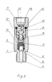
- the metering device consists of body 1, in which inlet channel 2 and working chamber 3 are formed lying axially.
- the transition between the input channel 2 and the working chamber 3 is a conical surface 4.
- a plunger 5 is loosely mounted, which is made of elastic material.
- a cavity 6, which is open on one side, is formed and the surface from this side of the plunger 5 is identical to the conical surface 4.
- the working chamber 3 of the metering device is closed by a hollow nut 7 mounted on an external thread 8.
- the hollow nut has a central step-shaped through opening 9 and is compressed to the body 1 by the compression ring 10.
- the plunger 5 is formed from the side of the hollow nut 7 with a step in which the disk 11 is mounted.
- the spring 12 is supported to the disk 11 and its other end is inserted in the nut 7.
- a conventional ball return valve is assembled, which consists of ball 13, spring 14 and counter disk 15.
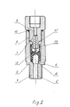
- second cavity 16 which is open on one side, is formed in the plunger 5 from the side of the hollow nut 7.
- the spring 12 is located centrally in the second cavity 16 of the plunger 5 and in one step of the through opening 9 of the hollow nut 7.
- the hollow nut 7 is provided from the side of the plunger 5 with a shaped mandrel 17, the outer surface of which is in the immediate vicinity of the thread 8 is conical and is cylindrical at its other end.
- the diameter of the cylindrical part of the dome 17 is smaller than the largest Diameter of the conical part of the dome 17.
- the mandrel 17 itself is partly in the second cavity 16.
- the metering device works as follows: When the lubricating oil is supplied by the pump, it will enter the inlet channel 2 and enter the cavity 6 of the plunger 5. As a result of the pressure increase, the walls of the cavity 6 are pressed against the walls of the working chamber 3, thereby pressing them The plunger is compressed in the working chamber 3 and functions as a piston. If the pressure of the supplied lubricating oil is greater than the spring force 12, which presses the plunger 5 towards the conical surface 4, the plunger 5 moves to the hollow nut 7, whereby the oil in the working chamber is expelled through the opening 9 of the hollow nut 7. This lasts until the plunger 5 hits the entrance of the central stepped through opening 9 of the hollow nut 7.
- the supplied oil of the plunger is let through the mounted back valve into the opening 9 of the hollow nut 7.
- the same opening 9 is opened by the back valve against the backflow of the oil from its outlet side dosing device. This creates conditions for the valuable filling of the working chamber 3 with a new oil portion.
- the plunger 5 bumps into the conical surface of the dome 17 of the hollow nut 7 with the end of its second cavity 16. Because of the elasticity of the plunger 5, its ends will encompass the conical surface of the dome 17 and they become the oil flow to the passage opening 9 In this position the pump stops working and the pressure in the working chamber 3 is reduced.
- the spring 12 tries to bring the plunger 5 back into the starting position and the ends of the first cavity 6 are drawn together and the oil fills the working chamber 3 out. Proceeding, the ends of the second cavity 16 of the plunger 5 will further encompass the mandrel 17, playing a role of the return valve, holding the beautifully ejected oil so that it does not penetrate into the working chamber 3 before it is filled with the new portion of oil is.
- the ends of the second cavity 16 of the plunger 5 are separated from the walls of the dome 17 and the plunger 5 is brought into the starting position.
- the invention relates to a metering device for fluid, in particular for metering lubricating oils, which ensures an exact and repetitive metering of the fluid portions, regardless of the parameter change of the system in which it is installed, and has a simple and technological construction and unification of the elements of which it is made possible.
- the metering device consists of a body in which the inlet channel and working chamber are formed centrally, which in turn is closed by a hollow nut with a central step-shaped through opening.
- a spring plunger is loosely mounted in the working chamber.
- the transition from the working chamber to the input channel is a conical surface open cavity shaped.
Abstract
Description
Die Erfindung betrifft eine Dosiereinrichtung für Fluid, insbesondere zum Dosieren von Schmieröle und ist zum Schmieren von Werkzeugmaschinen geeignet.The invention relates to a metering device for fluid, in particular for metering lubricating oils, and is suitable for lubricating machine tools.
Es ist bereits eine Dosiereinrichtung dieser Art bekannt, die aus einem Körper besteht, in den sich Eingangskanal und mit ihm verbundene Arbeitskammer zentralliegend befinden,Die Arbeitskammer ist von einer Hohlmutter mit zentralen,stufenartigen Durchgangsöffnung geschloßen.ln der Arbeitskammer und in der Öffnung der Hohlmutter befindet sich locker einen Plunger, der so spezifisch ist, daß seinem Grund einen größeren Durchmesser aufweist als der anderen, in der Öffnung der Hohlmutter sich befindenden Teil.Der Durchgang zwischen dem Grund und dem anderen Teil des Plungers ist kegelförmig.Die Verbindung zwischen dem Körper und der Hohlmutter ist gewindeartig und ist mit einem Verdichtungsring verdichtet.Der Plunger ist von der Seite der Hohlmutter durch eine Feder unterstützt.Es ist ein Kugelrückventil in der Hohlmutter vorgesehen./1/A metering device of this type is already known, which consists of a body in which the input channel and the working chamber connected to it are located centrally. The working chamber is closed by a hollow nut with a central, step-like passage opening. It is located in the working chamber and in the opening of the hollow nut a plunger that is so specific that its base has a larger diameter than the other part located in the opening of the hollow nut. The passage between the base and the other part of the plunger is conical. The connection between the body and The hollow nut is thread-like and is compressed with a compression ring. The plunger is supported by a spring from the side of the hollow nut. A ball check valve is provided in the hollow nut.
Einen Nachteil dieser Dosiereinrichtung ist,daß mit ihm ein exaktes,genaues Dosieren des Fluides nicht gesichert ist, und diese in großen Grenzen in Abhängigkeit von der Spannungsgröße,von der eingebauten im System Dosiereinrichtungsanzahl, von der Viskosität,von der Temperatur und der Sauberkeit der Schmieröle u.s.w. variert.Bei verschiedenen Mengen de Dosierportion verändern sich in der Konstruktion die Abmessungen des Körpers, des Plungers und der anderen Bauelemente,das die Unifizierung der entsprechenden Elemente behindert.A disadvantage of this metering device is that it does not ensure an exact, exact metering of the fluid, and this within large limits depending on the voltage level, the number of metering devices installed in the system, the viscosity, the temperature and the cleanliness of the lubricating oils etc With different amounts of the dosing portion, the dimensions of the body, the plunger and the other components change in the construction, which hinders the unification of the corresponding elements.
Die Aufgabe der Erfindung ist eine Dosiereinrichtung für Fluid zu schaffen , die die exakte und sich wiederholende Dosieung der Fluidportionen, unabhängig von der Parameteränderungen des Systems, in dem sie eingebaut ist, sichert und eine einfache und technologische Konstruktion aufweist und eine Unifizierung der Elemente aus der sie besteht, ermöglicht.The object of the invention is to provide a dosing device for fluid, which ensures the exact and repetitive dosing of the fluid portions, regardless of the parameter changes of the system in which it is installed, and has a simple and technological construction and unification of the elements from the it exists.
Die Aufgabe wird erfindungsgemäß durch eine Dosiereinrichtung gelöst,die aus einem Körper besteht, in dem Eingangskanal und Arbeitskammer zentralliegend geförmt sind,die ihrerseits durch eine Hohlmutter mit zentralen stufenförmigen Durchgangsöffnung geschloßen ist.ln der Arbeitskammer ist einen Unterfederplunger locker montiert.Erfindungsgemäß ist der Übergang von der Arbeitskammer zu den Eingangskanal eine Kegelfläche. Solche Kegelfläche weist auch die dazuliegende Oberfläche des Plungers.Dieser Plunger ist aus einem elastischen Material ausgearbeitet und von der Seite des Eingangskanal ist in ihm einen einseitig geöffneten Hohlraum geförmt.The object is achieved according to the invention by a metering device which consists of a body in which the inlet channel and working chamber are formed centrally, which in turn is closed by a hollow nut with a central step-shaped passage opening. A spring base is loosely mounted in the working chamber the working chamber to the input channel a conical surface. Such a conical surface also has the surface of the plunger lying there. This plunger is made of an elastic material and a cavity open on one side is formed in it from the side of the inlet channel.
In einer bevorzugten Erfindungsausführung ist das innere Ende des Plungers mit geformter Stufe ausgearbeitet, in der für den Plunger eine Gegenscheibe montiert ist.ln der Hohlmutter ist einen konventionelen Kugelrückventil eingebaut.In a preferred embodiment of the invention, the inner end of the plunger is worked out with a shaped step in which a counter washer is mounted for the plunger. A conventional ball return valve is installed in the hollow nut.
In einer zweiten bevorzugten Erfindungsausführung ist in dem inneren Ende des Plungers einen zweiten Hohlraum geformt, der einseitig zu der Hohlmutter geöffnet ist, die einen Dorn-(vorspringendes Element) aufweist, der sich in der zweiten Hohlraum befindet.Die Außenfläche des Dorns,die sich in unmittelbaren Nähe des Hohlmuttergewinde befindet ist kegelförmig und in ihrer Ende ist sie zylindrisch.Der Durchmesser des zweiten Hohlraumes ist kleiner als der größten Durchmesser des kegelförmigen Teils des Doms.In a second preferred embodiment of the invention, a second cavity is formed in the inner end of the plunger which is open on one side to the hollow nut which has a mandrel (protruding element) which is located in the second cavity. The outer surface of the mandrel which is located in the immediate vicinity of the hollow nut thread is conical and in its end it is cylindrical. The diameter of the second cavity is smaller than the largest diameter of the conical part of the dome.
Erfindungsgemäß werden die Vorteile der Dosiereinrichtung vor allem durchdie spezifische Konstruktion des Plungers und durch das Material, aus den er ausgearbeitet ist, besimmt. Auf dieser Weise ist die Konstriktion vereinfacht und technologisch.Die Elastizität des Materials ,aus dem den Plunger ausgearbeitet ist, garantiert eine konstante Dose des zugeführten Öls, bei längeren Anwendung.Es ist eine maximale Unifizierung der Dosiereinrichtung bildenden Elemente möglich.According to the invention, the advantages of the metering device are primarily determined by the specific construction of the plunger and by the material from which it is made. In this way, the constriction is simplified and technological. The elasticity of the material from which the plunger is made guarantees a constant dose of the supplied oil, with prolonged use. A maximum unification of the elements forming the dosing device is possible.
Anhand der beigefüg ten Zeichnungen wird ein Ausführungsbeispiel der Erfindung gezeigt,wobei:
Figur 1 stellt einen Längsschnitt durch die Achse der Dosiereinrichtung mit in der Hohlmutter eingebauten Kugelrückventil ,dar.Figur 2 Längsschnitt durch die Achse der Dosiereinrichtung bei der zweiten Variantenausführung, ohne Rückventil.
- FIG. 1 shows a longitudinal section through the axis of the metering device with a ball return valve installed in the hollow nut.
- Figure 2 shows a longitudinal section through the axis of the metering device in the second variant, without a back valve.
Die Dosiereinrichtung besteht aus Körper 1,in dem Eingangskanal 2 und Arbeitskammer 3 axial- liegend,geformt sind. Der Übergang zwischen den Eingangskanal 2 und der Arbeitskammer 3 ist eine Kegelfläche 4.ln der Arbeitskammer 3 ist locker einen Plunger 5 montiert,der aus elasischen Material ausgearbeitet ist.ln dem Plunger 5 ist einen einseitig geöffneten zu den Eingangkanal2 Hohlraum 6 geformt und die Fläche aus dieser Seite des Plungers 5 ist identisch mit der Kegelfläche 4. Die Arbeitskammer 3 der Dosiereinrichtung ist durch eine auf Außengewinde 8 montierte Hohlmutter 7 geschloßen.Die Hohlmutter weist eine zentrale stufenförmige Durchgangsöffnung 9 auf und ist zu dem Körper 1 durch den Verdichtungsring 10 verdichtet.The metering device consists of
In der einer Variantenausführung der Dosiereinrichtung ist der Plunger 5 von der Seite der Hohlmutter 7 mit einer Stufe geformt, in der Die Scheibe 11 montiert ist. Zu der Scheibe 11 ist die Feder 12 gestützt und derren andere Ende in der Mutter 7 gesteckt ist.ln der Hohlmutter 7 selbst ist ein konventionelen Kugelrückventil montiert,das aus Kugel 13, Feder 14 und Gegenscheibe 15 besteht.In one variant of the metering device, the
In der zweiten Ausführung der Dosiereinrichtung ist in dem Plunger 5 von der Seite der Hohlmutter 7 einseitig geöffneten zweiten Hohlraum 16 geformt.Die Feder 12 ist zentral in dem zweiten Hohlraum 16 des Plungers 5 und in der einen Stufe der Durchgangsöffnung 9 der Hohlmutter 7 gelegen. Die Hohlmutter 7 ist von der Seite des Plungers 5 mit einem geformten Dorn 17 versehen,dessen in unmittelbaren Nähe des Gewindes 8 sich befindende Außenfläche kegelförmig ist und an ihrer andere Ende zylindrisch ist.Der Durchmesser des zylindrischen Teil des Domes 17 ist kleiner als der größten Durchmesser des kegelförmigen Teils des Domes 17. Der Dorn 17 selbst befindet sich teilweise in dem zweiten Hohlraum 16.In the second embodiment of the metering device,
Die Dosiereinrichtung funktioniert wie folgt: Beim Zuführen des Schmieröls von der Pumpe wird es in den Eingangskanal 2 eintretten und gelangt in den Hohlraum 6 des Plungers 5.lnfolge der Druckerhöhung werden die Wände des Hohlraumes 6 zu den Wände der Arbeitskammer 3 gedrückt, wobei auf dieser Weise wird den Plunger in der Arbeitskammer 3 verdichtet und funktioniert als ein Kolben.Wenn der Druck des zugeführten Schmieröls größer als die Federkraft 12, die den Plunger 5 zu der Kegelfläche 4 drückt, ist,dann versetzt sich der Plunger 5 zur Hohlmutter 7,wobei das sich in der Arbeitskammer sich befindenden Öl durch die Öffnung 9 der Hohlmutter 7 ausgestoßen wird.Dieses dauert bis zu dem der Plunger 5 stoßt auf den Eingang der zentralen stufenförmigen Durchgangsöffnung 9 der Hohlmutter 7 auf.ln dieser Lage wird der Druck des zugeführten Öls steil zunehmen und die Pumpe hört auf zu funktionieren. Es folgt einen Druckabfall in der Arbeitskammer 3 und wird den Plunger, unter der Einwirkung der Feder 12 in die Ausgangslage zurückgeführt, wobei in dem Raum hinter ihm, in die Arbeitskammer 3 Öl eindringt, wegen des Fakts, daß die Wände des Hohlraumes 6 des Plungers 5 zusammengezogen sind.The metering device works as follows: When the lubricating oil is supplied by the pump, it will enter the
In der ersten Variante wird von dem montierten Rückventil in die Öffnung 9 der Hohlmutter 7, das zugeführten Öl des Plungers durchgelassen.Im Moment des Zuschließens der Öffnung 9 vom Plunger 5 wird von dem Rückventil dei selbe Öffnung 9 gegen den Rückfluß des Öls von seiner Ausgangsseite der Dosiereinrichtung,zugeschloßen .Dieses schafft Bedingungen zum wertvollen Ausfüllen der Arbeitskammer 3 mit einer neuen Ölportion.In the first variant, the supplied oil of the plunger is let through the mounted back valve into the opening 9 of the
Bei der zweiten Erfindungsvariante stoßt der Plunger 5 mit dem Ende seines zweiten Hohlraumes 16 in die Kegelfläche des Domes 17 der Hohlmutter 7.Wegen der Elastizität des Plungers 5 werden seinen Enden die Kegelfläche des Domes 17 umfaßen und sie werden den Ölstrom zu der Durchgangsöffnung 9 der Hohlmutter 7 unterbrechen.In dieser Lage hört die Pumpe auf zu funktionieren und wird der Druck in der Arbeitskammer 3 herabgesetzt.Die Feder 12 strebt nach Zurückbringen des Plungers 5 in die Ausgangslage und die Enden des ersten Hohlraumes 6 werden zusammengezogen und das Öl füllt die Arbeitskammer 3 aus. Ausgehend werden die Enden des zweiten Hohlraumes 16 des Plungers 5 den Dorn 17 weiter dicht umfaßen, wobei sie eine Rolle des Rückventils spielen, haltend so das schön ausgestoßenen Öl, daß es nicht in die Arbeitskammer 3 eindringt,bevor sie mit der neuen Portion Öl aufgefüllt ist. Nach dem Druckausgleich seitlich des Plungers 5,werden die Enden des zweiten Hohlraumes 16 des Plungers 5 von der Wänden des Domes 17 getrennt und der Plunger 5 wird in die Ausgangslage gebracht.In the second variant of the invention, the
Die Erfindung betrifft eine Dosiereinrichtung für Fluid, insbesondere zum Dosieren von Schmieröle,die eine exakte und sich wiederholende Dosierung der Fluidportionen,unabhängig von der Parameteränderung des Systems,in dem sie eingebaut ist, sichert und eine einfache und technologische Konstruktion aufweist und eine Unifizierung der Elemente aus der sie besteht, erröglicht.The invention relates to a metering device for fluid, in particular for metering lubricating oils, which ensures an exact and repetitive metering of the fluid portions, regardless of the parameter change of the system in which it is installed, and has a simple and technological construction and unification of the elements of which it is made possible.
Die Dosiereinrichtung besteht aus einem Körper, in dem Eingangskanal und Arbeitskammer zentralliegend geformt sind, die ihrerseits durch eine Hohlmutter mit zentralen stufenförmigen Durchgangsöffnung geschloßen ist. In der Arbeitskammer ist einen Unterfederplunger locker montiert.Erfindungsgemäß ist der Übergang von der Arbeitskammer zu den Eingangskanal eine Kegelfläche.Solche Kegelfläche weist auch dazuliegende Oberfläche des Plungers.Dieser Plunger ist aus einem elastischen Material ausgearbeitet und von der Seite des Eingangskanal ist in ihm einen einseitig geöffneten Hohlraum geformt.The metering device consists of a body in which the inlet channel and working chamber are formed centrally, which in turn is closed by a hollow nut with a central step-shaped through opening. In the working chamber, a spring plunger is loosely mounted. According to the invention, the transition from the working chamber to the input channel is a conical surface open cavity shaped.
Es sind zwei Erfindungsausführungen in der Beschreibung erläutert.Two embodiments of the invention are explained in the description.
Claims (3)
LITERATUR:
1. Urheberschein der VRBulgarien No.40 2663. Dosing device according to claim 1, characterized in that in the inner end of the plunger / 5 / a second, one-sided to the hollow nut / 7 /, cavity / 16 / is formed, the hollow nut having a mandrel / 17 /, the Outer surface near the thread / 8 / the hollow nut / 7 / is conical and is cylindrical at the end, with the mandrel / 17 / in the cavity / 16 /, the diameter of the second cavity / 16 / smaller than that largest diameter of the conical part of the mandrel / 17 /.
LITERATURE:
1.Copyright of VRBulgarien No.40 266
Priority Applications (1)
| Application Number | Priority Date | Filing Date | Title |
|---|---|---|---|
| EP90125555A EP0491988A1 (en) | 1990-12-27 | 1990-12-27 | Metering device for fluid |
Applications Claiming Priority (1)
| Application Number | Priority Date | Filing Date | Title |
|---|---|---|---|
| EP90125555A EP0491988A1 (en) | 1990-12-27 | 1990-12-27 | Metering device for fluid |
Publications (1)
| Publication Number | Publication Date |
|---|---|
| EP0491988A1 true EP0491988A1 (en) | 1992-07-01 |
Family
ID=8204897
Family Applications (1)
| Application Number | Title | Priority Date | Filing Date |
|---|---|---|---|
| EP90125555A Withdrawn EP0491988A1 (en) | 1990-12-27 | 1990-12-27 | Metering device for fluid |
Country Status (1)
| Country | Link |
|---|---|
| EP (1) | EP0491988A1 (en) |
Cited By (5)
| Publication number | Priority date | Publication date | Assignee | Title |
|---|---|---|---|---|
| WO1994011644A1 (en) * | 1992-11-19 | 1994-05-26 | Ina Wälzlager Schaeffler Kg | Linear bearing component |
| EP0855550A1 (en) * | 1997-01-22 | 1998-07-29 | Alex S.p.A. | Easily assembled metering valve |
| CN1312428C (en) * | 2004-07-23 | 2007-04-25 | 象山县久源润滑件有限公司 | Unloading method for grease multiple point central quantitative lubricating pipeline and self suction load device |
| CN101985998A (en) * | 2010-11-26 | 2011-03-16 | 浙江胜祥机械有限公司 | Oil dripping valve |
| US9752461B2 (en) | 2013-02-05 | 2017-09-05 | General Electric Technology Gmbh | Steam power plant with a second low-pressure turbine and an additional condensing system |
Citations (2)
| Publication number | Priority date | Publication date | Assignee | Title |
|---|---|---|---|---|
| US1837811A (en) * | 1928-10-15 | 1931-12-22 | Farfall Company | Measuring nipple for lubricating systems |
| GB791455A (en) * | 1954-07-24 | 1958-03-05 | Emmerich Satzger | Dispenser for lubricants |
-
1990
- 1990-12-27 EP EP90125555A patent/EP0491988A1/en not_active Withdrawn
Patent Citations (2)
| Publication number | Priority date | Publication date | Assignee | Title |
|---|---|---|---|---|
| US1837811A (en) * | 1928-10-15 | 1931-12-22 | Farfall Company | Measuring nipple for lubricating systems |
| GB791455A (en) * | 1954-07-24 | 1958-03-05 | Emmerich Satzger | Dispenser for lubricants |
Cited By (7)
| Publication number | Priority date | Publication date | Assignee | Title |
|---|---|---|---|---|
| WO1994011644A1 (en) * | 1992-11-19 | 1994-05-26 | Ina Wälzlager Schaeffler Kg | Linear bearing component |
| US5496113A (en) * | 1992-11-19 | 1996-03-05 | Ina Walzlager Schaeffler Kg | Linear bearing element |
| DE4395740C1 (en) * | 1992-11-19 | 1997-06-12 | Schaeffler Waelzlager Kg | Lubrication and sealing device for linear rolling bearing elements |
| EP0855550A1 (en) * | 1997-01-22 | 1998-07-29 | Alex S.p.A. | Easily assembled metering valve |
| CN1312428C (en) * | 2004-07-23 | 2007-04-25 | 象山县久源润滑件有限公司 | Unloading method for grease multiple point central quantitative lubricating pipeline and self suction load device |
| CN101985998A (en) * | 2010-11-26 | 2011-03-16 | 浙江胜祥机械有限公司 | Oil dripping valve |
| US9752461B2 (en) | 2013-02-05 | 2017-09-05 | General Electric Technology Gmbh | Steam power plant with a second low-pressure turbine and an additional condensing system |
Similar Documents
| Publication | Publication Date | Title |
|---|---|---|
| DE3640669C2 (en) | Fluid dispenser | |
| DE2641171B2 (en) | Writing implement | |
| DE1500597B2 (en) | Dip tube atomizer | |
| DE10231751B4 (en) | Suction-pressure pump for ejecting a product from a container | |
| DE10334032B4 (en) | valve means | |
| WO2004067988A1 (en) | Damper especially for movable parts of pieces of furniture | |
| EP0444036B1 (en) | Applicator pen for liquids | |
| EP1779023B1 (en) | Single line distributor | |
| DE1653402B2 (en) | Exhaust valve assembly | |
| EP0688988B1 (en) | Dripfree valve | |
| DE3630911C2 (en) | ||
| DE69814961T2 (en) | Micropump for nebulizing fluids | |
| EP1631767A1 (en) | Distributing element for lubricating systems | |
| DE2906992C2 (en) | ||
| DE1920450C3 (en) | Grease cup | |
| EP0491988A1 (en) | Metering device for fluid | |
| DE2651133A1 (en) | DOSING VALVE FOR LUBRICATION SYSTEMS WORKING UNDER PRESSURE | |
| DE2711208C2 (en) | Device for dosing and filling especially highly viscous media | |
| DE19614446C1 (en) | Grease gun check valve | |
| DE3525449C2 (en) | Output device for flowable media | |
| DE2949202A1 (en) | ELECTRICALLY ACTUATED FLUID CONTROL DEVICE | |
| EP0388651B1 (en) | Device for discharging a fluid | |
| DE102007011192A1 (en) | Dosing device for a lubricant dispenser | |
| DE3922956C2 (en) | ||
| DE60302566T2 (en) | FLUID PRODUCT SUPPLY PUMP |
Legal Events
| Date | Code | Title | Description |
|---|---|---|---|
| PUAI | Public reference made under article 153(3) epc to a published international application that has entered the european phase |
Free format text: ORIGINAL CODE: 0009012 |
|
| AK | Designated contracting states |
Kind code of ref document: A1 Designated state(s): AT DE FR GB IT |
|
| STAA | Information on the status of an ep patent application or granted ep patent |
Free format text: STATUS: THE APPLICATION IS DEEMED TO BE WITHDRAWN |
|
| 18D | Application deemed to be withdrawn |
Effective date: 19930102 |