EP0491790B1 - Field lighting installation - Google Patents
Field lighting installation Download PDFInfo
- Publication number
- EP0491790B1 EP0491790B1 EP90913745A EP90913745A EP0491790B1 EP 0491790 B1 EP0491790 B1 EP 0491790B1 EP 90913745 A EP90913745 A EP 90913745A EP 90913745 A EP90913745 A EP 90913745A EP 0491790 B1 EP0491790 B1 EP 0491790B1
- Authority
- EP
- European Patent Office
- Prior art keywords
- lamp
- current
- installation
- circuit
- series
- Prior art date
- Legal status (The legal status is an assumption and is not a legal conclusion. Google has not performed a legal analysis and makes no representation as to the accuracy of the status listed.)
- Expired - Lifetime
Links
- 238000009434 installation Methods 0.000 title claims description 33
- 230000001105 regulatory effect Effects 0.000 claims description 13
- 238000012544 monitoring process Methods 0.000 claims description 9
- 230000001360 synchronised effect Effects 0.000 claims description 2
- 239000003990 capacitor Substances 0.000 description 3
- 238000000034 method Methods 0.000 description 2
- 230000001681 protective effect Effects 0.000 description 2
- 230000015556 catabolic process Effects 0.000 description 1
- 239000004020 conductor Substances 0.000 description 1
- 230000001276 controlling effect Effects 0.000 description 1
- 239000013078 crystal Substances 0.000 description 1
- 230000003247 decreasing effect Effects 0.000 description 1
- 230000000694 effects Effects 0.000 description 1
- 238000005286 illumination Methods 0.000 description 1
- 230000001939 inductive effect Effects 0.000 description 1
- 238000002955 isolation Methods 0.000 description 1
- 230000008054 signal transmission Effects 0.000 description 1
- 230000009466 transformation Effects 0.000 description 1
- 230000001052 transient effect Effects 0.000 description 1
Images


Classifications
-
- H—ELECTRICITY
- H05—ELECTRIC TECHNIQUES NOT OTHERWISE PROVIDED FOR
- H05B—ELECTRIC HEATING; ELECTRIC LIGHT SOURCES NOT OTHERWISE PROVIDED FOR; CIRCUIT ARRANGEMENTS FOR ELECTRIC LIGHT SOURCES, IN GENERAL
- H05B39/00—Circuit arrangements or apparatus for operating incandescent light sources
- H05B39/04—Controlling
- H05B39/08—Controlling by shifting phase of trigger voltage applied to gas-filled controlling tubes also in controlled semiconductor devices
-
- H—ELECTRICITY
- H05—ELECTRIC TECHNIQUES NOT OTHERWISE PROVIDED FOR
- H05B—ELECTRIC HEATING; ELECTRIC LIGHT SOURCES NOT OTHERWISE PROVIDED FOR; CIRCUIT ARRANGEMENTS FOR ELECTRIC LIGHT SOURCES, IN GENERAL
- H05B39/00—Circuit arrangements or apparatus for operating incandescent light sources
- H05B39/10—Circuits providing for substitution of the light source in case of its failure
- H05B39/105—Circuits providing for substitution of the light source in case of its failure with a spare lamp in the circuit, and a possibility of shunting a failed lamp
-
- H—ELECTRICITY
- H05—ELECTRIC TECHNIQUES NOT OTHERWISE PROVIDED FOR
- H05B—ELECTRIC HEATING; ELECTRIC LIGHT SOURCES NOT OTHERWISE PROVIDED FOR; CIRCUIT ARRANGEMENTS FOR ELECTRIC LIGHT SOURCES, IN GENERAL
- H05B47/00—Circuit arrangements for operating light sources in general, i.e. where the type of light source is not relevant
- H05B47/20—Responsive to malfunctions or to light source life; for protection
- H05B47/23—Responsive to malfunctions or to light source life; for protection of two or more light sources connected in series
Definitions
- the present invention relates to a field lighting installation, including a plurality of series connected light fittings supplied from an A.C. mains via a converter unit, said converter unit being adapted to convert the substantially constant voltage obtained from the mains to a substantially constant current in departing current lines of a power cable containing the light fittings, each light fitting being adapted to include a lamp, a regulator unit supplied with said constant current on the power cable being associated with each light fitting or group of light fittings for individual regulation of the current passing through the associated lamp or lamps.
- GB-A-1 424 802 which document forms the base for the preamble of Claim 1, discloses a field lighting installation with a constant current feeding the lamp fittings, a regulator unit for individual regulation of the current passing through the lamp, the regulator unit receiving control information through a separate cable.
- DE-C-470 324 and GB-A-367 430 describe the use of Boucherot circuits having no connection with airfield lighting plants and not discussing the particular problems which can occur in such plants.
- the traditional method of controlling and monitoring field lights on an airfield is to supply power to the different light configurations via a so-called parallel system or a so-called series system, cf. Figures 1 and 2.
- the regulating and monitoring unit is centrally placed in a cabinet or the like, and its regulators provide either a contstant voltage (parallel system) or a constant current (series system) to the different power supply cables to the different field light configurations.
- the object of the present invention is to achieve a field lighting installation of the kind mentioned in the introduction, wherein individual control of the light fittings, or groups thereof, is possible while cable costs are considerably reduced at the same time.
- each regulator unit is disposed to receive control information via the power cable and in that the converter unit includes a Boucherot circuit having a series resonance circuit, substantially tuned on the mains frequency, and an additional inductance in series with a load connected to the converter unit.
- the converter unit adapted for converting the voltage obtained from the A.C. mains to a substantially constant current is a so-called Boucherot circuit with a series resonance circuit, tuned substantially to the mains frequency.
- Boucherot circuit is described more in detail by E. Arnold, Die Kirstromtechnik, Managerer Band, Zweite Auflage, Verlag Julius Springer, Berlin, pp 141-4.
- the converter unit includes a further inductance in series with a load connected to the converter unit. If this inductance is of the same magnitude as the one included in the series resonance circuit, there will be obtained the advantage that during idling, i.e. short-circuiting of the current system, the current in the network ideally will be zero.
- Another advantage in the utilization of this special Boucherot circuit is that the effect on the network is small and that the sinus wave shape is maintained essentially unaffected, which facilitates signal transmission over the power cables, and is generally advantageous in applications for airfields, where a low interference level is essential.
- the regulator unit includes a counter synchronized to the zero crossings of the current, said counter being intended for current regulation controlled by a set binary number.
- the regulator unit includes a triac or thyristor connected in parallel with the lamp of the light fitting for regulating the current through the lamp.
- the installation in accordance with the invention also preferably includes a safety system, suitably having three levels, since a fault that could lead to an open circuit would cause impermissibly high voltages.
- the installation according to the invention therefore includes transient protection, primarily in the shape of a component, e.g. a type of two-way Zener diode, which is connected across each lamp and which is short-circuited (not interrupted) when it is driven outside its operating range.
- the triac can be disposed such that in response to over-voltage occurring across the lamp it is forced to a permanent "on" state for short-circuiting the transients, and as a third protection means there can be arranged a (mechanical and/or electronic) device for short-circuiting any occurring over-voltages, if these are not short-circuited by the other protective means.
- Figures 1 and 2 illustrate the principles of so-called parallel and series supply, respectively, for filed lightings on an airfield according to prior art.
- Figure 3 illustrates the principle of the installation according to the invention and
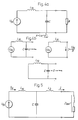
- Figure 4a illustrates the basic implementation of the so-called Boucherot circuit included in the converter unit of the installation according to the invention
- Figure 4b illustrates the electrical properties of the circuit.
- Figure 5 illustrates a further development of the Boucherot circuit
- Figure 6 illustrates the further developed Boucherot circuit of Figure 5 included in the installation according to the invention
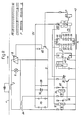
- Figure 7 schematically illustrates an example of a local regulating and monitoring unit in the installation according to the invention
- Figure 8 illustrates the unit of Figure 7 in more detail.
- FIG. 3 there is schematically illustrated an embodiment of the installation according to the invention, in which a series system of a plurality of light fittings is supplied from a current generator 10.
- Each fitting includes a lamp 6 as well as a local regulating and monitoring unit 12.
- the output voltage is not regulated, and becomes a function of the prevailing load.
- the regulating and monitoring units 12 are given their control information, suitably from a central control system, by signals carried on the power cable, a separate control cable or by radio.
- the current source is realised by a converter unit supplied from an A.C. mains having substantially constant voltage.
- This converter unit converts the voltage obtained from the mains to a substantially constant current in the departing lines which include the light fittings.
- the converter unit includes a Boucherot circuit, illustrated in its basic implementation in Figure 4a.
- the circuit contains a series resonance circuit formed of an inductance L N and a capacitor C and is tuned substantially to the mains frequency.
- the properties of the Boucherot circuit are as follows. When it is supplied with the voltage U N from the mains the voltage seen from the load side is infinitely great when the load impedance goes towards infinity and for a short-circuited load the impedance is formed of the reactance in the inductance L N , cf Figure 4b.
- the circuit may be represented by an infinitely great EMF behind an infinite impedance, i.e. it constitutes a current source.
- I N I and is purely inductive.
- FIG. 5 there is shown a further advantageous development of the Boucherot circuit, which is used in the installation according to the invention.
- a second inductance L2 is connected in series with the load Z bel . If the inductance L2 is of the same magnitude as the series resonance circuit inductance L N , one of the advantages with this embodiment is that the mains current I N is equal to zero, when the system is short-circuited, i.e. in a no-load state, since L2 and C are in parallel resonance.
- the load has been assumed to be linear, namely a resistance in series with an (ideal) inductance.
- the load consists of a resistance, i.e. the lamp 6, which is connected in parallel with a triac 8, cf figures 6-8.
- the effective value of the current through the lamp can then be varied by varying the ignition angle of the triac 8.
- This combined load is non-linear, but in spite of this the current from the Boucherot circuit is practically sinusoidal, due to the inductance L2 at the output. As previously mentioned, this affords important advantages.
- the Boucherot circuit When the triac 8 is disconnected at the beginning of each half period the Boucherot circuit is resistively loaded, and when the triac 8 is connected for the rest of the half period the Boucherot circuit is short-circuited.
- the wave form of the voltage across the load is also formed of a part of a sinus form that can be divided into fundamental tone and overtones.
- the overtones will be (almost) filtered away by the inductances and capacitance of the circuit, while the fundamental tone of the voltage can be divided into an active component, in phase with the current, and a reactive component, phase shifted 90° forwards of the current.
- the load acts as a resistive-inductive load.
- FIG 6 there is shown an example of a series system of field lights of the kind to which the invention relates, and supplied from a Boucherot circuit via a current transformer 14 on the output side.
- the series line is loaded by a plurality of current transformers 2, each of which is connected to one or more light fittings on the secondary side.
- Via a switch 16 the Boucherot circuit is connected between the phases of an ordinary 3-phase mains 18. Several such circuits can be connected distributed between the phases of the mains to balance the 3-phase load.
- the installation must be provided with protective means, since very high voltages will occur if a light fitting should form an open circuit, e.g. because of a lamp failure.
- the triac 8 connected in parallel with the lamp 6 is adapted to be permanently turned-on for short-circuiting the lamp, should the lamp fail. If the circuit for turning on the triac should not enter into function, there is a second over-voltage protection in the form of a two-way Zener diode 20 connected across the lamp 6, and it will be short-circuited if an overvoltage occurs across the lamp.
- the Boucherot circuit is further protected by a short-circuitng means comprising two anti-parallel connected thyristors 22 across the output transformer 14. If the line with the transformers should form an open circuit, e.g.
- the short-circuiting means 22 will start to function and short-circuit the Boucherot circuit. If the operation mechanism of the short-circuiting means 22 should not function a break-down will occur in the thyristor as a result of the overvoltage, and a permanent short-circuit will be established. Only a limited overvoltage will appear in the installation for a very short time, and this overvoltage can be used to activate an alarm and for triggering the switch 16, suitably with time a delay of a few periods, so that the current has time to be decay.
- the installation shown in Figure 6 thus includes a threefold overvoltage protection.
- each light fitting includes a local regulator unit 12 (not shown in Figure 6).
- a local regulator unit 12 (not shown in Figure 6).
- An example of such a unit is cursorily illustrated in Figure 7.
- the regulating and monitoring unit includes a conventional current transformer 2, as isolation between the power supply 4 and the lamp 6, as well as a triac 8 connected in parallel with the lamp 6, for regulating the light intensity of the latter. Thyristors can be used instead of the triac 8 for regulating illumination.
- the current transformer 2 drives a constant current through the secondary side and with the triac 8 not turned on the entire secondary side current flows through the lamp 6. By gradually turning on the triac 8 there is obtained a gradually decreasing current through the lamp 6.
- the light intensity from the lamp can thus be regulated in this way, which will be explained in greater detail below in connection with Figure 8.
- the regulating and monitoring unit illustrated in figures 7 and 8 may be essentially divided into: Power supply, detector, counter and amplifier.
- the power supply includes an auxiliary transformer 24, which may be a current transformer having a high transformation ratio, the secondary side of which is connected to a rectifier bridge 26.
- the rectified output voltage from the rectifier bridge 26 is smoothed by a capacitor 28 and stabilised by a Zener diode 30.
- the detector is connected to the A.C. terminals of the rectifier bridge 26, where the voltage has a square wave configuration and is in phase with the current in the line containing the light fittings.
- the steepness of the flanks of the square wave are improved with the aid of comparators 32, 34 and the square wave is converted into a short pulse PE, which is repeated every half period by transferring the output voltages of the comparators 32, 34 to the base of a transistor 36 via their respective capacitors 38, 40.
- This zero point detector will thus send a pulse PE for each zero crossing of the current in the line containing the light fittings.
- the counter includes a crystal-controlled oscillator with a binary counter 42, which generates a clock pulse C1, which in turn clocks a following 8 bit binary count-down counter 44.
- the count-down counter 44 is activated by the pulse PE , which sets it to the binary number N, to be found at the inputs J0, J1...J7. After N counts the count-down counter 44 delivers a short output pulse CO .
- This pulse CO sets an RS-flipflop to zero 46, which is set to the "one" state by the pulse PE .
- the pulse CO sets the output of the flipflop 46 to 0, in which state it remains for the rest of half period.
- the pulse trains PE, CO and P are shown in the upper right-hand part of Figure 8.
- the binary number N is individual for each lamp 6 and is transferred ot the address of the light fitting in question from a computer in the central control system. This transfer is most cheaply achieved by using the power cable, but it can also be effected via separate signal cables or per radio, as already mentioned.
Landscapes
- Circuit Arrangement For Electric Light Sources In General (AREA)
- Circuit Arrangements For Discharge Lamps (AREA)
- Preparation Of Compounds By Using Micro-Organisms (AREA)
- Control Of Eletrric Generators (AREA)
- Discharge-Lamp Control Circuits And Pulse- Feed Circuits (AREA)
- Dc-Dc Converters (AREA)
- Arrangement Of Elements, Cooling, Sealing, Or The Like Of Lighting Devices (AREA)
- Supplying Of Containers To The Packaging Station (AREA)
Abstract
Description
- The present invention relates to a field lighting installation, including a plurality of series connected light fittings supplied from an A.C. mains via a converter unit, said converter unit being adapted to convert the substantially constant voltage obtained from the mains to a substantially constant current in departing current lines of a power cable containing the light fittings, each light fitting being adapted to include a lamp, a regulator unit supplied with said constant current on the power cable being associated with each light fitting or group of light fittings for individual regulation of the current passing through the associated lamp or lamps.
- Through US
patent specification 4 754 201 there is known a field lighting installation including a plurality of series connected light fittings, supplied from an A.C. mains via a converter unit adapted to convert the substantially constant voltage obtained from the mains to a substantially constant current in departing current lines containing the fittings. - GB-A-1 424 802, which document forms the base for the preamble of
Claim 1, discloses a field lighting installation with a constant current feeding the lamp fittings, a regulator unit for individual regulation of the current passing through the lamp, the regulator unit receiving control information through a separate cable. - DE-C-470 324 and GB-A-367 430 describe the use of Boucherot circuits having no connection with airfield lighting plants and not discussing the particular problems which can occur in such plants.
- The traditional method of controlling and monitoring field lights on an airfield is to supply power to the different light configurations via a so-called parallel system or a so-called series system, cf. Figures 1 and 2. In such a case, the regulating and monitoring unit is centrally placed in a cabinet or the like, and its regulators provide either a contstant voltage (parallel system) or a constant current (series system) to the different power supply cables to the different field light configurations.
- The object of the present invention is to achieve a field lighting installation of the kind mentioned in the introduction, wherein individual control of the light fittings, or groups thereof, is possible while cable costs are considerably reduced at the same time.
- This object is obtained, in accordance with the invention, in that each regulator unit is disposed to receive control information via the power cable and in that the converter unit includes a Boucherot circuit having a series resonance circuit, substantially tuned on the mains frequency, and an additional inductance in series with a load connected to the converter unit.
- In the installation according to the invention different light configurations are supplied by one or more transformers, implemented such that they may be regarded as representing current supply sources. Each light fitting is provided with a local regulating and monitoring unit, which obtains its control information via signals carried by the power cable. In the installation in accordance with the invention there is thus used a "current supply" network where the prevailing output voltage will be a function of the prevailing load. The advantages accompanying the use of such a current supply system in a field lighting installation for airfields are as follows:
- 1) The lamps have a resistance that varies heavily, depending on the filament temperature, a current supplying system then providing a smooth successive voltage increase across the lamp, whereas a voltage supplying system results in severe current surges when the lamp is turned on;
- 2) the lamps are spread over large areas, and if a current supplying system is used, single conductor, high-voltage cables, typically for 5 kW, can be used for the supply, which considerably reduces cable costs; and
- 3) current transformers are cheaper than corresponding voltage transformers.
- Further, in accordance with the invention, the converter unit adapted for converting the voltage obtained from the A.C. mains to a substantially constant current is a so-called Boucherot circuit with a series resonance circuit, tuned substantially to the mains frequency. This is a simple and advantageous method of obtaining a current source having an indefinite EMF behind an infinite impedance. The Boucherot circuit is described more in detail by E. Arnold, Die Wechselstromtechnik, Erster Band, Zweite Auflage, Verlag Julius Springer, Berlin, pp 141-4.
- Furthermore, in the installation according to the invention, the converter unit includes a further inductance in series with a load connected to the converter unit. If this inductance is of the same magnitude as the one included in the series resonance circuit, there will be obtained the advantage that during idling, i.e. short-circuiting of the current system, the current in the network ideally will be zero.
- Another advantage in the utilization of this special Boucherot circuit is that the effect on the network is small and that the sinus wave shape is maintained essentially unaffected, which facilitates signal transmission over the power cables, and is generally advantageous in applications for airfields, where a low interference level is essential.
- In accordance with an advantageous embodiment of the installation according to the invention the regulator unit includes a counter synchronized to the zero crossings of the current, said counter being intended for current regulation controlled by a set binary number.
- In accordance with a further advantageous embodiment of the installation according to the invention the regulator unit includes a triac or thyristor connected in parallel with the lamp of the light fitting for regulating the current through the lamp.
- The installation in accordance with the invention also preferably includes a safety system, suitably having three levels, since a fault that could lead to an open circuit would cause impermissibly high voltages. The installation according to the invention therefore includes transient protection, primarily in the shape of a component, e.g. a type of two-way Zener diode, which is connected across each lamp and which is short-circuited (not interrupted) when it is driven outside its operating range. As further protection, the triac can be disposed such that in response to over-voltage occurring across the lamp it is forced to a permanent "on" state for short-circuiting the transients, and as a third protection means there can be arranged a (mechanical and/or electronic) device for short-circuiting any occurring over-voltages, if these are not short-circuited by the other protective means.
- In order to explain the invention more in detail, an embodiment of the installation according to the invention, selected as an example, will now be described while referring to Figures 3-8.
- On the drawings, Figures 1 and 2 illustrate the principles of so-called parallel and series supply, respectively, for filed lightings on an airfield according to prior art. Figure 3 illustrates the principle of the installation according to the invention and Figure 4a illustrates the basic implementation of the so-called Boucherot circuit included in the converter unit of the installation according to the invention, and Figure 4b illustrates the electrical properties of the circuit. Figure 5 illustrates a further development of the Boucherot circuit, Figure 6 illustrates the further developed Boucherot circuit of Figure 5 included in the installation according to the invention, Figure 7 schematically illustrates an example of a local regulating and monitoring unit in the installation according to the invention and Figure 8 illustrates the unit of Figure 7 in more detail.
- In Figure 3 there is schematically illustrated an embodiment of the installation according to the invention, in which a series system of a plurality of light fittings is supplied from a
current generator 10. Each fitting includes alamp 6 as well as a local regulating andmonitoring unit 12. The output voltage is not regulated, and becomes a function of the prevailing load. The regulating andmonitoring units 12 are given their control information, suitably from a central control system, by signals carried on the power cable, a separate control cable or by radio. - The current source is realised by a converter unit supplied from an A.C. mains having substantially constant voltage. This converter unit converts the voltage obtained from the mains to a substantially constant current in the departing lines which include the light fittings.
- The converter unit includes a Boucherot circuit, illustrated in its basic implementation in Figure 4a. The circuit contains a series resonance circuit formed of an inductance LN and a capacitor C and is tuned substantially to the mains frequency.
- The properties of the Boucherot circuit are as follows. When it is supplied with the voltage UN from the mains the voltage seen from the load side is infinitely great when the load impedance goes towards infinity and for a short-circuited load the impedance is formed of the reactance in the inductance LN, cf Figure 4b.
- By applying Thevenin's theorem, the circuit may be represented by an infinitely great EMF behind an infinite impedance, i.e. it constitutes a current source. The magnitude of the current is: I=UN/X, where X = ω LN is the reactance of the inductance, and this current is equal to the short-circuiting current. When the circuit is short-circuited the current in the load line is IN = I and is purely inductive.
- In Figure 5 there is shown a further advantageous development of the Boucherot circuit, which is used in the installation according to the invention. In this embodiment a second inductance L₂ is connected in series with the load Zbel. If the inductance L₂ is of the same magnitude as the series resonance circuit inductance LN, one of the advantages with this embodiment is that the mains current IN is equal to zero, when the system is short-circuited, i.e. in a no-load state, since L₂ and C are in parallel resonance.
- In the description so far of the Boucherot circuit the load has been assumed to be linear, namely a resistance in series with an (ideal) inductance. In the installation according to the invention, the load consists of a resistance, i.e. the
lamp 6, which is connected in parallel with atriac 8, cf figures 6-8. The effective value of the current through the lamp can then be varied by varying the ignition angle of thetriac 8. This combined load is non-linear, but in spite of this the current from the Boucherot circuit is practically sinusoidal, due to the inductance L₂ at the output. As previously mentioned, this affords important advantages. - When the
triac 8 is disconnected at the beginning of each half period the Boucherot circuit is resistively loaded, and when thetriac 8 is connected for the rest of the half period the Boucherot circuit is short-circuited. The wave form of the voltage across the load is also formed of a part of a sinus form that can be divided into fundamental tone and overtones. The overtones will be (almost) filtered away by the inductances and capacitance of the circuit, while the fundamental tone of the voltage can be divided into an active component, in phase with the current, and a reactive component, phase shifted 90° forwards of the current. In other words, the load acts as a resistive-inductive load. - In Figure 6 there is shown an example of a series system of field lights of the kind to which the invention relates, and supplied from a Boucherot circuit via a
current transformer 14 on the output side. The series line is loaded by a plurality ofcurrent transformers 2, each of which is connected to one or more light fittings on the secondary side. Via aswitch 16 the Boucherot circuit is connected between the phases of an ordinary 3-phase mains 18. Several such circuits can be connected distributed between the phases of the mains to balance the 3-phase load. - As already mentioned, the installation must be provided with protective means, since very high voltages will occur if a light fitting should form an open circuit, e.g. because of a lamp failure.
- The
triac 8 connected in parallel with thelamp 6 is adapted to be permanently turned-on for short-circuiting the lamp, should the lamp fail. If the circuit for turning on the triac should not enter into function, there is a second over-voltage protection in the form of a two-way Zenerdiode 20 connected across thelamp 6, and it will be short-circuited if an overvoltage occurs across the lamp. The Boucherot circuit is further protected by a short-circuitng means comprising two anti-parallel connectedthyristors 22 across theoutput transformer 14. If the line with the transformers should form an open circuit, e.g. due to a lamp failure, and the voltage across thetransformer 14 rises, the short-circuiting means 22 will start to function and short-circuit the Boucherot circuit. If the operation mechanism of the short-circuiting means 22 should not function a break-down will occur in the thyristor as a result of the overvoltage, and a permanent short-circuit will be established. Only a limited overvoltage will appear in the installation for a very short time, and this overvoltage can be used to activate an alarm and for triggering theswitch 16, suitably with time a delay of a few periods, so that the current has time to be decay. - The installation shown in Figure 6 thus includes a threefold overvoltage protection.
- As mentioned above in connection with the description of Figure 3, each light fitting includes a local regulator unit 12 (not shown in Figure 6). An example of such a unit is cursorily illustrated in Figure 7.
- The regulating and monitoring unit includes a conventional
current transformer 2, as isolation between thepower supply 4 and thelamp 6, as well as atriac 8 connected in parallel with thelamp 6, for regulating the light intensity of the latter. Thyristors can be used instead of thetriac 8 for regulating illumination. Thecurrent transformer 2 drives a constant current through the secondary side and with thetriac 8 not turned on the entire secondary side current flows through thelamp 6. By gradually turning on thetriac 8 there is obtained a gradually decreasing current through thelamp 6. The light intensity from the lamp can thus be regulated in this way, which will be explained in greater detail below in connection with Figure 8. - The regulating and monitoring unit illustrated in figures 7 and 8 may be essentially divided into: Power supply, detector, counter and amplifier.
- The power supply includes an
auxiliary transformer 24, which may be a current transformer having a high transformation ratio, the secondary side of which is connected to arectifier bridge 26. The rectified output voltage from therectifier bridge 26 is smoothed by acapacitor 28 and stabilised by aZener diode 30. - The detector is connected to the A.C. terminals of the
rectifier bridge 26, where the voltage has a square wave configuration and is in phase with the current in the line containing the light fittings. The steepness of the flanks of the square wave are improved with the aid ofcomparators comparators transistor 36 via theirrespective capacitors - The counter includes a crystal-controlled oscillator with a
binary counter 42, which generates a clock pulse C1, which in turn clocks a following 8 bit binary count-down counter 44. The count-down counter 44 is activated by the pulsePE , which sets it to the binary number N, to be found at the inputs J0, J1...J7. After N counts the count-down counter 44 delivers a short output pulseCO . This pulseCO sets an RS-flipflop to zero 46, which is set to the "one" state by the pulsePE . The pulseCO sets the output of the flipflop 46 to 0, in which state it remains for the rest of half period. The output signal P is amplified in theamplifier 48 and forms the control pulse turning on thetriac 8, which is turned on for P=O.
The pulse trains PE, CO and P are shown in the upper right-hand part of Figure 8. - The binary number N is individual for each
lamp 6 and is transferred ot the address of the light fitting in question from a computer in the central control system. This transfer is most cheaply achieved by using the power cable, but it can also be effected via separate signal cables or per radio, as already mentioned. - It has also been mentioned earlier that there is a means for turning the triac into a permanent on-state if there should be a lamp failure, and suitably there are also means (not shown) for sensing the condition of the
lamp 6 and sending information thereon back to the central control system computer, which can thus keep count of which lamps need to be changed.
Claims (9)
- Field lighting installation, including a plurality of series connected light fittings supplied from an A.C. mains via a converter unit (LN,C,L2), said converter unit (LN,C,L2) being adapted to convert the substantially constant voltage obtained from the mains to substantially constant current in departing current lines of a power cable (4) containing the light fitting, each light fitting being adapted to include a lamp (6), a regulator unit (12) supplied with said constant current on the power cable (4) being associated with each light fitting or group of light fitting for individual regulation of the current passing through the associated lamp or lamps (6), characterized in that each regulator unit (12) is disposed to receive control information via the power cable (4) and in that the converter unit (LN,C,L2) includes a Boucherot circuit having a series resonance circuit (LNC), substantially tuned on the mains frequency, and an additional inductance (L2) in series with a load (Zbel) connected to the converter unit.
- Installation as claimed in claim 1, characterized in that the regulator unit (12) includes a counter (42,44) synchronized to the zero crossings of the current, said counter being intended for current regulation controlled by a set binary number.
- Installation as claimed in claims 1 or 2, characterized in that the regulator unit (12) includes a triac (8) or thyristor connnected in parallel with the lamp (6) of the light fitting for regulating the current through the lamp.
- Installation as claimed in any one of claims 1-3, characterized in that the regulator unit (12) also includes means for monitoring the operational state of the lamp (6) in the light fitting.
- Installation as claimed in any one of claims 1-4, characterized in that there is provided over-voltage protection in the form of a component, preferably a two-way Zener diode (20), which is short-circuited when it is driven outside its operation range, said component being connected across each lamp (6).
- Installation as claimed in any one of claims 3-5, characterized in that the triac (8) connected in parallel with the lamp is adapted to be forced in a permanent on-state in response to the occurrence of overvoltage across the lamp (6) for short-circuiting until a resetting signal is given.
- Installation as claimed in claim 6, characterized in that a short-circuiting means (22) is arranged across the primary side of a transformer (14) connected to the output of the Boucherot circuit for short-circuiting the transformer if an overvoltage should occur.
- Installation as claimed in any one of claims 1-7, characterized in that the regulator units (12) are adapted for being controlled from a central control system.
- Installation as claimed in any one of claims 1-8, characterized in that said additional inductance (L2) in series with a load is of equal magnitude as the inductance included in the series resonance circuit.
Applications Claiming Priority (3)
| Application Number | Priority Date | Filing Date | Title |
|---|---|---|---|
| SE8903028 | 1989-09-14 | ||
| SE8903028A SE467132B (en) | 1989-09-14 | 1989-09-14 | FAELTLJUSANORDNING |
| PCT/SE1990/000582 WO1991004647A1 (en) | 1989-09-14 | 1990-09-12 | Field lighting installation |
Publications (2)
| Publication Number | Publication Date |
|---|---|
| EP0491790A1 EP0491790A1 (en) | 1992-07-01 |
| EP0491790B1 true EP0491790B1 (en) | 1995-06-28 |
Family
ID=20376880
Family Applications (1)
| Application Number | Title | Priority Date | Filing Date |
|---|---|---|---|
| EP90913745A Expired - Lifetime EP0491790B1 (en) | 1989-09-14 | 1990-09-12 | Field lighting installation |
Country Status (9)
| Country | Link |
|---|---|
| US (1) | US5239236A (en) |
| EP (1) | EP0491790B1 (en) |
| JP (1) | JP2866893B2 (en) |
| AT (1) | ATE124597T1 (en) |
| AU (1) | AU642166B2 (en) |
| DE (1) | DE69020571T2 (en) |
| ES (1) | ES2076372T3 (en) |
| SE (1) | SE467132B (en) |
| WO (1) | WO1991004647A1 (en) |
Cited By (1)
| Publication number | Priority date | Publication date | Assignee | Title |
|---|---|---|---|---|
| EP2579690A2 (en) | 2011-10-07 | 2013-04-10 | LUCEBIT GmbH | Airport lighting system |
Families Citing this family (23)
| Publication number | Priority date | Publication date | Assignee | Title |
|---|---|---|---|---|
| SE462698B (en) * | 1988-10-07 | 1990-08-13 | Swedish Airport Technology Han | FAIR LIGHTING FOR AIRPORT |
| IT1256123B (en) * | 1992-07-22 | 1995-11-29 | AUTOMATIC LIGHTS CONTROL SYSTEM OF A SERIES CIRCUIT LIGHTING SYSTEM, IN PARTICULAR FOR AIRPORT SIGNAL LAMPS. | |
| US5485151A (en) * | 1993-05-06 | 1996-01-16 | Adb-Alnaco, Inc. | Airfield lighting system |
| US5638057A (en) * | 1994-05-09 | 1997-06-10 | Adb-Alnaco, Inc. | Ground fault detection and measurement system for airfield lighting system |
| US5648723A (en) * | 1994-05-09 | 1997-07-15 | Adb-Alnaco, Inc. | Method and apparatus for separating and analyzing composite AC/DC waveforms |
| US20080129214A1 (en) * | 1995-06-26 | 2008-06-05 | Jlj, Inc. | Miniature light base unit with shunt for random twinkle |
| US7178961B2 (en) * | 1995-06-26 | 2007-02-20 | Jlj, Inc. | Voltage regulated light string |
| US20090039794A1 (en) * | 1995-06-26 | 2009-02-12 | Janning John L | Miniature light bulb for random high-low twinkle in series-wired light string |
| US5926115A (en) * | 1996-06-21 | 1999-07-20 | Adb Alnaco, Inc. | Airfield series circuit communications lighting system and method |
| US6035266A (en) * | 1997-04-16 | 2000-03-07 | A.L. Air Data, Inc. | Lamp monitoring and control system and method |
| US6714895B2 (en) * | 2000-06-28 | 2004-03-30 | A.L. Air Data, Inc. | Lamp monitoring and control unit and method |
| EP1002449A1 (en) * | 1997-08-05 | 2000-05-24 | Siemens Aktiengesellschaft | Method and device for stabilizing the series circuit current of lighting installations at airports and similar |
| IT1306314B1 (en) * | 1998-07-08 | 2001-06-04 | Ocem Spa | ADAPTER DEVICE FOR INSERTING A LOAD IN AN IMPRESSED CURRENT CIRCUIT |
| WO2002093711A1 (en) | 2001-05-17 | 2002-11-21 | Stay Lit International, Inc. | Voltage regulated light string |
| US20100045202A1 (en) * | 2006-06-30 | 2010-02-25 | Cooper Technologies Company | Interface Device for Low Power LED Airfield Lighting System |
| US20100045186A1 (en) * | 2006-10-04 | 2010-02-25 | Janning John L | Dual brightness twinkle in a miniature light bulb |
| US20110031896A1 (en) * | 2007-10-09 | 2011-02-10 | Jean-Claude Vandevoorde | Lighting device for lighting the airfield of an airport |
| US9008992B2 (en) | 2011-03-25 | 2015-04-14 | Thomas & Betts International, Inc. | Testing and monitoring an electrical system |
| US8907587B2 (en) | 2012-07-25 | 2014-12-09 | Cooper Technologies Company | Stand-alone synchronization for a runway light |
| EP2720516A1 (en) * | 2012-10-09 | 2014-04-16 | Toshiba Lighting & Technology Corporation | Load control device and lighting apparatus |
| US9554444B2 (en) | 2012-12-17 | 2017-01-24 | OV20 Systems | Device and method for retrofitting or converting or adapting series circuits |
| DE102016011115B3 (en) * | 2016-09-16 | 2017-10-05 | Systemtechnik LEBER GmbH & Co. KG | Arrangement and method for protecting persons from dangerous contact voltage in series circuits with series circuit and lamp transformers |
| FI127536B (en) * | 2016-11-03 | 2018-08-31 | Ellego Powertec Oy | Power supply |
Family Cites Families (9)
| Publication number | Priority date | Publication date | Assignee | Title |
|---|---|---|---|---|
| DE25404C (en) * | A. RlNCKLAKE, Professor in Braunschweig | Devices for sealing the kerosene lamps | ||
| DE470324C (en) * | 1926-04-23 | 1929-01-14 | Aeg | Device for the optional conversion of electrical work from constant AC voltage into work from constant current or vice versa |
| GB367430A (en) * | 1930-11-20 | 1932-02-22 | Gen Electric Co Ltd | Improved means for obtaining constant voltage in alternating current circuits |
| US3771120A (en) * | 1971-12-27 | 1973-11-06 | Gte Sylvania Inc | Airport runway approach and reference lighting system |
| GB1424802A (en) * | 1972-01-28 | 1976-02-11 | Plessey Co Ltd | Series circuit control systems |
| US4242614A (en) * | 1979-02-26 | 1980-12-30 | General Electric Company | Lighting control system |
| GB2174852B (en) * | 1985-05-02 | 1988-12-07 | Tann Electronics Ltd | Airfield lighting installations |
| DE3635682A1 (en) | 1986-10-21 | 1988-04-28 | Bbc Brown Boveri & Cie | Monitoring device for lamp failure in airfield lighting systems |
| LU86815A1 (en) * | 1987-03-19 | 1988-11-17 | Jacques Mawet | DEVICE FOR RE-ESTABLISHING THE LINE CURRENT IN THE EVENT OF A BREAKDOWN OF ONE OR MORE PULSE ELEMENTS OF A SERIES MOUNTING |
-
1989
- 1989-09-14 SE SE8903028A patent/SE467132B/en not_active IP Right Cessation
-
1990
- 1990-09-12 AU AU64020/90A patent/AU642166B2/en not_active Ceased
- 1990-09-12 WO PCT/SE1990/000582 patent/WO1991004647A1/en not_active Ceased
- 1990-09-12 US US07/829,090 patent/US5239236A/en not_active Expired - Fee Related
- 1990-09-12 AT AT90913745T patent/ATE124597T1/en not_active IP Right Cessation
- 1990-09-12 DE DE69020571T patent/DE69020571T2/en not_active Expired - Fee Related
- 1990-09-12 ES ES90913745T patent/ES2076372T3/en not_active Expired - Lifetime
- 1990-09-12 JP JP2512959A patent/JP2866893B2/en not_active Expired - Fee Related
- 1990-09-12 EP EP90913745A patent/EP0491790B1/en not_active Expired - Lifetime
Cited By (3)
| Publication number | Priority date | Publication date | Assignee | Title |
|---|---|---|---|---|
| EP2579690A2 (en) | 2011-10-07 | 2013-04-10 | LUCEBIT GmbH | Airport lighting system |
| DE102011115104A1 (en) | 2011-10-07 | 2013-04-11 | LUCEBIT GmbH | Airport lighting system |
| DE102011115104B4 (en) * | 2011-10-07 | 2020-12-31 | Adb Safegate Germany Gmbh | Airport lighting system |
Also Published As
| Publication number | Publication date |
|---|---|
| AU6402090A (en) | 1991-04-18 |
| SE8903028D0 (en) | 1989-09-14 |
| ES2076372T3 (en) | 1995-11-01 |
| WO1991004647A1 (en) | 1991-04-04 |
| SE8903028L (en) | 1991-03-15 |
| JPH05505055A (en) | 1993-07-29 |
| DE69020571T2 (en) | 1996-01-11 |
| US5239236A (en) | 1993-08-24 |
| JP2866893B2 (en) | 1999-03-08 |
| AU642166B2 (en) | 1993-10-14 |
| SE467132B (en) | 1992-05-25 |
| EP0491790A1 (en) | 1992-07-01 |
| DE69020571D1 (en) | 1995-08-03 |
| ATE124597T1 (en) | 1995-07-15 |
Similar Documents
| Publication | Publication Date | Title |
|---|---|---|
| EP0491790B1 (en) | Field lighting installation | |
| US5073848A (en) | Power distribution system | |
| US4207497A (en) | Ballast structure for central high frequency dimming apparatus | |
| US4949020A (en) | Lighting control system | |
| US6559562B1 (en) | Voltage sag and over-voltage compensation device with pulse width modulated autotransformer | |
| AU2018232948B2 (en) | Multi-module dc-to-dc power transformation system | |
| US4688161A (en) | Regulated power supply apparatus and method using reverse phase angle control | |
| EP0621678B1 (en) | Overvoltage protection circuit | |
| GB2091051A (en) | Dc-to-ac converter | |
| RU2473163C2 (en) | High-voltage inverter | |
| CA1077135A (en) | Cycloconverter apparatus and method for working into an active load | |
| CA2292442C (en) | Low voltage illumination system | |
| US8072192B2 (en) | Auxiliary power supply with a coupling capacitor between a high voltage line and ground | |
| US20140204614A1 (en) | Rectified high frequency power supply with low total harmonic distortion (thd) | |
| US4626953A (en) | Doubly overload-protected power distribution system | |
| US6426611B1 (en) | Constant voltage lamp controller | |
| US4816738A (en) | Tap changing power regulator for airport lighting | |
| US4607324A (en) | Reduced harmonic current rectifier including sequentially switched secondary windings | |
| EP0010811A1 (en) | Switching transistor over-voltage protection means | |
| RU2025911C1 (en) | Outdoor lighting system | |
| US4639662A (en) | Thyristor circuit for current regulation | |
| Hehenkamp | Thyristor inverters for fluorescent lighting | |
| SU1032510A1 (en) | Device for single-phase earth fault protection in isolated neutral system | |
| RU34283U1 (en) | Uninterruptible power supply unit | |
| WO1989010024A1 (en) | Arrangement for controlled energy transfer for electrical supply, especially for reducing switching transients |
Legal Events
| Date | Code | Title | Description |
|---|---|---|---|
| PUAI | Public reference made under article 153(3) epc to a published international application that has entered the european phase |
Free format text: ORIGINAL CODE: 0009012 |
|
| 17P | Request for examination filed |
Effective date: 19920204 |
|
| AK | Designated contracting states |
Kind code of ref document: A1 Designated state(s): AT BE CH DE DK ES FR GB IT LI LU NL SE |
|
| RAP1 | Party data changed (applicant data changed or rights of an application transferred) |
Owner name: AIRPORT TECHNOLOGY IN SCANDINAVIA AB |
|
| 17Q | First examination report despatched |
Effective date: 19931029 |
|
| GRAA | (expected) grant |
Free format text: ORIGINAL CODE: 0009210 |
|
| AK | Designated contracting states |
Kind code of ref document: B1 Designated state(s): AT BE CH DE DK ES FR GB IT LI LU NL SE |
|
| PG25 | Lapsed in a contracting state [announced via postgrant information from national office to epo] |
Ref country code: NL Free format text: LAPSE BECAUSE OF NON-PAYMENT OF DUE FEES Effective date: 19950628 Ref country code: LI Effective date: 19950628 Ref country code: DK Effective date: 19950628 Ref country code: CH Effective date: 19950628 Ref country code: AT Effective date: 19950628 |
|
| REF | Corresponds to: |
Ref document number: 124597 Country of ref document: AT Date of ref document: 19950715 Kind code of ref document: T |
|
| REF | Corresponds to: |
Ref document number: 69020571 Country of ref document: DE Date of ref document: 19950803 |
|
| ITF | It: translation for a ep patent filed | ||
| PG25 | Lapsed in a contracting state [announced via postgrant information from national office to epo] |
Ref country code: SE Effective date: 19950928 |
|
| REG | Reference to a national code |
Ref country code: CH Ref legal event code: PL |
|
| PG25 | Lapsed in a contracting state [announced via postgrant information from national office to epo] |
Ref country code: LU Free format text: LAPSE BECAUSE OF NON-PAYMENT OF DUE FEES Effective date: 19950930 |
|
| ET | Fr: translation filed | ||
| REG | Reference to a national code |
Ref country code: ES Ref legal event code: FG2A Ref document number: 2076372 Country of ref document: ES Kind code of ref document: T3 |
|
| NLV1 | Nl: lapsed or annulled due to failure to fulfill the requirements of art. 29p and 29m of the patents act | ||
| PLBI | Opposition filed |
Free format text: ORIGINAL CODE: 0009260 |
|
| PLBF | Reply of patent proprietor to notice(s) of opposition |
Free format text: ORIGINAL CODE: EPIDOS OBSO |
|
| 26 | Opposition filed |
Opponent name: SIEMENS AG Effective date: 19960319 |
|
| PLBF | Reply of patent proprietor to notice(s) of opposition |
Free format text: ORIGINAL CODE: EPIDOS OBSO |
|
| PLBF | Reply of patent proprietor to notice(s) of opposition |
Free format text: ORIGINAL CODE: EPIDOS OBSO |
|
| PLBO | Opposition rejected |
Free format text: ORIGINAL CODE: EPIDOS REJO |
|
| APAC | Appeal dossier modified |
Free format text: ORIGINAL CODE: EPIDOS NOAPO |
|
| APAE | Appeal reference modified |
Free format text: ORIGINAL CODE: EPIDOS REFNO |
|
| APAC | Appeal dossier modified |
Free format text: ORIGINAL CODE: EPIDOS NOAPO |
|
| REG | Reference to a national code |
Ref country code: FR Ref legal event code: TP |
|
| REG | Reference to a national code |
Ref country code: GB Ref legal event code: 732E |
|
| REG | Reference to a national code |
Ref country code: GB Ref legal event code: IF02 |
|
| PGFP | Annual fee paid to national office [announced via postgrant information from national office to epo] |
Ref country code: FR Payment date: 20030228 Year of fee payment: 13 |
|
| PGFP | Annual fee paid to national office [announced via postgrant information from national office to epo] |
Ref country code: GB Payment date: 20030303 Year of fee payment: 13 |
|
| PGFP | Annual fee paid to national office [announced via postgrant information from national office to epo] |
Ref country code: ES Payment date: 20030325 Year of fee payment: 13 |
|
| PGFP | Annual fee paid to national office [announced via postgrant information from national office to epo] |
Ref country code: BE Payment date: 20030327 Year of fee payment: 13 |
|
| PGFP | Annual fee paid to national office [announced via postgrant information from national office to epo] |
Ref country code: DE Payment date: 20030328 Year of fee payment: 13 |
|
| APBU | Appeal procedure closed |
Free format text: ORIGINAL CODE: EPIDOSNNOA9O |
|
| PLBN | Opposition rejected |
Free format text: ORIGINAL CODE: 0009273 |
|
| STAA | Information on the status of an ep patent application or granted ep patent |
Free format text: STATUS: OPPOSITION REJECTED |
|
| PG25 | Lapsed in a contracting state [announced via postgrant information from national office to epo] |
Ref country code: GB Free format text: LAPSE BECAUSE OF NON-PAYMENT OF DUE FEES Effective date: 20030912 |
|
| PG25 | Lapsed in a contracting state [announced via postgrant information from national office to epo] |
Ref country code: ES Free format text: LAPSE BECAUSE OF NON-PAYMENT OF DUE FEES Effective date: 20030913 |
|
| PG25 | Lapsed in a contracting state [announced via postgrant information from national office to epo] |
Ref country code: BE Free format text: LAPSE BECAUSE OF NON-PAYMENT OF DUE FEES Effective date: 20030930 |
|
| 27O | Opposition rejected |
Effective date: 19981218 |
|
| BERE | Be: lapsed |
Owner name: *SAFEGATE INTERNATIONAL A.B. Effective date: 20030930 |
|
| PG25 | Lapsed in a contracting state [announced via postgrant information from national office to epo] |
Ref country code: DE Free format text: LAPSE BECAUSE OF NON-PAYMENT OF DUE FEES Effective date: 20040401 |
|
| GBPC | Gb: european patent ceased through non-payment of renewal fee |
Effective date: 20030912 |
|
| PG25 | Lapsed in a contracting state [announced via postgrant information from national office to epo] |
Ref country code: FR Free format text: LAPSE BECAUSE OF NON-PAYMENT OF DUE FEES Effective date: 20040528 |
|
| REG | Reference to a national code |
Ref country code: FR Ref legal event code: ST |
|
| REG | Reference to a national code |
Ref country code: ES Ref legal event code: FD2A Effective date: 20030913 |
|
| PG25 | Lapsed in a contracting state [announced via postgrant information from national office to epo] |
Ref country code: IT Free format text: LAPSE BECAUSE OF NON-PAYMENT OF DUE FEES;WARNING: LAPSES OF ITALIAN PATENTS WITH EFFECTIVE DATE BEFORE 2007 MAY HAVE OCCURRED AT ANY TIME BEFORE 2007. THE CORRECT EFFECTIVE DATE MAY BE DIFFERENT FROM THE ONE RECORDED. Effective date: 20050912 |
|
| APAH | Appeal reference modified |
Free format text: ORIGINAL CODE: EPIDOSCREFNO |