EP0491663A1 - Procedure and apparatus for the examination of optical components, particularly ophthalmic components, and device for the illumination of transparent objects under examination - Google Patents
Procedure and apparatus for the examination of optical components, particularly ophthalmic components, and device for the illumination of transparent objects under examination Download PDFInfo
- Publication number
- EP0491663A1 EP0491663A1 EP19910810978 EP91810978A EP0491663A1 EP 0491663 A1 EP0491663 A1 EP 0491663A1 EP 19910810978 EP19910810978 EP 19910810978 EP 91810978 A EP91810978 A EP 91810978A EP 0491663 A1 EP0491663 A1 EP 0491663A1
- Authority
- EP
- European Patent Office
- Prior art keywords
- image
- reflector
- illumination
- test
- lighting device
- Prior art date
- Legal status (The legal status is an assumption and is not a legal conclusion. Google has not performed a legal analysis and makes no representation as to the accuracy of the status listed.)
- Granted
Links
- 230000003287 optical effect Effects 0.000 title claims abstract description 38
- 238000000034 method Methods 0.000 title claims abstract description 21
- 238000005286 illumination Methods 0.000 title claims description 28
- 238000004519 manufacturing process Methods 0.000 claims abstract description 48
- 238000010191 image analysis Methods 0.000 claims abstract description 29
- 230000007547 defect Effects 0.000 claims abstract description 14
- 238000012360 testing method Methods 0.000 claims description 78
- 238000012545 processing Methods 0.000 claims description 15
- 238000001514 detection method Methods 0.000 claims description 7
- 238000003860 storage Methods 0.000 claims description 5
- 230000005855 radiation Effects 0.000 claims description 2
- 230000006978 adaptation Effects 0.000 claims 1
- 230000003667 anti-reflective effect Effects 0.000 claims 1
- 238000007689 inspection Methods 0.000 abstract description 8
- 230000010354 integration Effects 0.000 abstract 1
- 238000003908 quality control method Methods 0.000 description 10
- 230000015654 memory Effects 0.000 description 7
- 239000000463 material Substances 0.000 description 5
- 239000011888 foil Substances 0.000 description 4
- 238000012544 monitoring process Methods 0.000 description 4
- 238000006116 polymerization reaction Methods 0.000 description 4
- 239000012634 fragment Substances 0.000 description 3
- 239000007788 liquid Substances 0.000 description 3
- 230000001419 dependent effect Effects 0.000 description 2
- 238000010586 diagram Methods 0.000 description 2
- 239000011521 glass Substances 0.000 description 2
- 238000000465 moulding Methods 0.000 description 2
- 238000004806 packaging method and process Methods 0.000 description 2
- 238000005498 polishing Methods 0.000 description 2
- 239000000243 solution Substances 0.000 description 2
- 238000012369 In process control Methods 0.000 description 1
- 229910045601 alloy Inorganic materials 0.000 description 1
- 239000000956 alloy Substances 0.000 description 1
- 238000004140 cleaning Methods 0.000 description 1
- 230000003749 cleanliness Effects 0.000 description 1
- 230000001427 coherent effect Effects 0.000 description 1
- 230000002950 deficient Effects 0.000 description 1
- 238000006073 displacement reaction Methods 0.000 description 1
- 239000000428 dust Substances 0.000 description 1
- 238000011156 evaluation Methods 0.000 description 1
- 239000012530 fluid Substances 0.000 description 1
- 230000006870 function Effects 0.000 description 1
- 230000036571 hydration Effects 0.000 description 1
- 238000006703 hydration reaction Methods 0.000 description 1
- 238000003384 imaging method Methods 0.000 description 1
- 230000001771 impaired effect Effects 0.000 description 1
- 238000010965 in-process control Methods 0.000 description 1
- 238000002347 injection Methods 0.000 description 1
- 239000007924 injection Substances 0.000 description 1
- 238000009434 installation Methods 0.000 description 1
- 238000003754 machining Methods 0.000 description 1
- 229910052751 metal Inorganic materials 0.000 description 1
- 239000002184 metal Substances 0.000 description 1
- 150000002739 metals Chemical class 0.000 description 1
- 210000000056 organ Anatomy 0.000 description 1
- 238000009304 pastoral farming Methods 0.000 description 1
- 238000003672 processing method Methods 0.000 description 1
- 238000004381 surface treatment Methods 0.000 description 1
- 230000000007 visual effect Effects 0.000 description 1
- 238000003466 welding Methods 0.000 description 1
- 238000013316 zoning Methods 0.000 description 1
Images


Classifications
-
- G—PHYSICS
- G01—MEASURING; TESTING
- G01J—MEASUREMENT OF INTENSITY, VELOCITY, SPECTRAL CONTENT, POLARISATION, PHASE OR PULSE CHARACTERISTICS OF INFRARED, VISIBLE OR ULTRAVIOLET LIGHT; COLORIMETRY; RADIATION PYROMETRY
- G01J1/00—Photometry, e.g. photographic exposure meter
-
- G—PHYSICS
- G01—MEASURING; TESTING
- G01M—TESTING STATIC OR DYNAMIC BALANCE OF MACHINES OR STRUCTURES; TESTING OF STRUCTURES OR APPARATUS, NOT OTHERWISE PROVIDED FOR
- G01M11/00—Testing of optical apparatus; Testing structures by optical methods not otherwise provided for
- G01M11/02—Testing optical properties
- G01M11/0242—Testing optical properties by measuring geometrical properties or aberrations
- G01M11/0278—Detecting defects of the object to be tested, e.g. scratches or dust
-
- G—PHYSICS
- G01—MEASURING; TESTING
- G01N—INVESTIGATING OR ANALYSING MATERIALS BY DETERMINING THEIR CHEMICAL OR PHYSICAL PROPERTIES
- G01N21/00—Investigating or analysing materials by the use of optical means, i.e. using sub-millimetre waves, infrared, visible or ultraviolet light
- G01N21/84—Systems specially adapted for particular applications
- G01N21/88—Investigating the presence of flaws or contamination
- G01N21/8851—Scan or image signal processing specially adapted therefor, e.g. for scan signal adjustment, for detecting different kinds of defects, for compensating for structures, markings, edges
- G01N2021/8887—Scan or image signal processing specially adapted therefor, e.g. for scan signal adjustment, for detecting different kinds of defects, for compensating for structures, markings, edges based on image processing techniques
-
- G—PHYSICS
- G01—MEASURING; TESTING
- G01N—INVESTIGATING OR ANALYSING MATERIALS BY DETERMINING THEIR CHEMICAL OR PHYSICAL PROPERTIES
- G01N21/00—Investigating or analysing materials by the use of optical means, i.e. using sub-millimetre waves, infrared, visible or ultraviolet light
- G01N21/84—Systems specially adapted for particular applications
- G01N21/88—Investigating the presence of flaws or contamination
- G01N21/95—Investigating the presence of flaws or contamination characterised by the material or shape of the object to be examined
- G01N2021/9511—Optical elements other than lenses, e.g. mirrors
-
- G—PHYSICS
- G01—MEASURING; TESTING
- G01N—INVESTIGATING OR ANALYSING MATERIALS BY DETERMINING THEIR CHEMICAL OR PHYSICAL PROPERTIES
- G01N21/00—Investigating or analysing materials by the use of optical means, i.e. using sub-millimetre waves, infrared, visible or ultraviolet light
- G01N21/84—Systems specially adapted for particular applications
- G01N21/88—Investigating the presence of flaws or contamination
- G01N21/95—Investigating the presence of flaws or contamination characterised by the material or shape of the object to be examined
- G01N21/958—Inspecting transparent materials or objects, e.g. windscreens
- G01N2021/9583—Lenses
Definitions
- both a dry test (air test) and a wet test (test in storage solution) of hydrated contact lenses can be carried out. If the components are housed in transparent containers, it is possible to carry out a final inspection of the components introduced.
Landscapes
- Physics & Mathematics (AREA)
- General Physics & Mathematics (AREA)
- Chemical & Material Sciences (AREA)
- Analytical Chemistry (AREA)
- Biochemistry (AREA)
- Pathology (AREA)
- Health & Medical Sciences (AREA)
- Life Sciences & Earth Sciences (AREA)
- Spectroscopy & Molecular Physics (AREA)
- General Health & Medical Sciences (AREA)
- Immunology (AREA)
- Geometry (AREA)
- Investigating Materials By The Use Of Optical Means Adapted For Particular Applications (AREA)
- Testing Of Optical Devices Or Fibers (AREA)
- Eye Examination Apparatus (AREA)
- Eyeglasses (AREA)
- Image Processing (AREA)
- Image Analysis (AREA)
Abstract
Description
Die Erfindung betrifft ein verfahren und eine vorrichtung zum Prüfen von optischen Bauteilen, bei dem von dem jeweils zu prüfenden Bauteil ein Bild hergestellt wird und durch Bildanalyse Fehler am abgebildeten Gegenstand erfasst werden, sowie eine Beleuchtungseinrichtung zum Beleuchten klar-transparenter Prüfungsobjekte.The invention relates to a method and a device for testing optical components, in which an image is made of the component to be tested in each case and errors in the depicted object are detected by image analysis, and a lighting device for illuminating clear-transparent test objects.
Bei der Herstellung und Qualitätsprüfung von optischen Bauteilen, insbesondere von augenoptischen Bauteilen, wie Kontaktlinsen, wird die Prüfung noch visuell durchgeführt. In diesem Zusammenhang kann beispielsweise auf die DIN-vorschrift 58 223 hingewiesen werden. Die visuelle Qualitätskontrolle stellt eine nur subjektive Prüfung dar, die personenabhängig ist und tageszeitlichen Schwankungen unterworfen wird. Damit ergeben sich bei der Qualitätsprüfung zwangsläufig verschiebungen der Qualitätsstandards, und es läßt sich eine ausreichende Reproduzierbarkeit der Qualität der Produkte nicht erreichen. Außerdem sind die Möglichkeiten einer Automatisierung, insbesondere bei der Massenfertigung solcher Bauteile, erheblich beeinträchtigt.In the manufacture and quality inspection of optical components, especially optical components such as contact lenses, the inspection is still carried out visually. In this context, reference may be made, for example, to DIN
Aus der EP 0 359 084 A2 ist es bei der Kontaktlinsenherstellung bekannt, das vorhandensein bzw. Fehlen von Kratzern und dergl. auf der gekrümmten Oberfläche der Linse durch eine optische Projektoreinrichtung und eine Bildverarbeitungseinrichtung zu erfassen. Aus der genannten Druckschrift ergibt sich jedoch nicht, wie die Projektoreinrichtung und die Bildverarbeitungseinrichtung ausgebildet sind, um sie für eine reproduzierbare Qualitätskontrolle, insbesondere bei der automatischen Fertigung von optischen Bauteilen, einsetzen zu können.From EP 0 359 084 A2 it is known in contact lens production to indicate the presence or absence of scratches and the like on the curved surface of the lens to detect an optical projector device and an image processing device. However, it is not clear from the cited document how the projector device and the image processing device are designed so that they can be used for reproducible quality control, in particular in the automatic production of optical components.
Bezüglich der Beleuchtung von Prüfobjekten ist bekannt, Objekte in einem Mikroskop mittels "Dunkelfeldbeleuchtung" zu beleuchten. Bei einer solchen Dunkelfeldbeleuchtung wird ein Objekt durch eine Lichtquelle und eine Beleuchtungsoptik (Kondensor) so beleuchtet, dass das Beleuchtungslichtbündel selbst nicht in den Strahlengang des Mikroskops gelangt. Becbachtet wird dann nur das von dem Objekt in den Strahlengang gestreute Licht.With regard to the illumination of test objects, it is known to illuminate objects in a microscope using "dark field illumination". With such dark field illumination, an object is illuminated by a light source and an illumination optics (condenser) in such a way that the illumination light bundle itself does not get into the beam path of the microscope. Then only the light scattered by the object into the beam path is observed.
Es sind Beleuchtungsoptiken für Dunkelfeldbeleuchtung bekannt, bei denen im Strahlengang eine zentrale Blendenscheibe angeordnet ist, welche den mittleren Teil des Beleuchtungslichtbündels abdeckt. Auf eine Kondensorlinse fällt dann ein ringförmiges Beleuchtungslichtbündel, das von den Randteilen der Kondensorlinse in der Ebene des Objekts gesammelt und dann seitlich an dem Strahlengana der Mikroskopoptik vorbeigeleitet wird.Illumination optics for dark field illumination are known in which a central diaphragm disk is arranged in the beam path and covers the central part of the illumination light bundle. A ring-shaped illuminating light beam then falls on a condenser lens, which is collected by the edge parts of the condenser lens in the plane of the object and then guided past the side of the beam organ of the microscope optics.
Es ist auch ein sog. "Kardioidkondensor" bekannt, bei welchem ein ringförmiges Beleuchtungslichtbündel an einer objektseitigen, konkaven Fläche einer ersten Linse total reflektiert wird. Das so nach aussen abgelenkte Lichtbündel fällt auf eine im wesentlichen zylindrische Mantelfläche einer zweiten Linse. Von dieser Mantelfläche wird das Lichtbündel wieder total reflektiert. Die zweite Linse sammelt das vom Rand her einwärts reflektierte Lichtbündel wieder in der Ebene des Objekts. Von dort aus läuft das Lichtbündel wieder konisch an dem Strahlengang des Mikroskops vorbei (Grimsehls Lehrbuch der Physik, 11. Aufl. (1943) Bd.2, Verl. B.G. Teubner, Seiten 707-708). Bei diesen bekannten Anordnungen handelt es sich um die Beleuchtung von Objekten in einem Mikroskop mit einer unveränderlichen Beleuchtungsoptik.A so-called "cardioid condenser" is also known, in which a ring-shaped illuminating light bundle on a concave surface of the object side of a first lens is total is reflected. The light beam thus deflected outwards falls on an essentially cylindrical outer surface of a second lens. The light beam is totally reflected again from this lateral surface. The second lens collects the light bundle reflected inwards from the edge again in the plane of the object. From there, the beam of light runs again conically past the beam path of the microscope (Grimsehls Textbook of Physics, 11th ed. (1943) vol. 2, publ. BG Teubner, pages 707-708). These known arrangements involve the illumination of objects in a microscope with an unchangeable illumination optics.
Ausgehend von diesem Stand der Technik ist es eine Aufgabe der Erfindung, ein Verfahren und eine Vorrichtung zur Prüfung von optischen Bauteilen zu schaffen, die zur Automatisierung der Prüfschritte und der Herstellung der optischen Bauteile beitragen. Weiterhin ist es eine Aufgabe der Erfindung, eine Beleuchtungseinrichtung zum Beleuchten klar-transparenter Prüfobjekte für die Untersuchung der Prüfobjekte auf Fehler zu schaffen, welche die Fehler deutlich erkennbar zu machen gestattet. Prüfobjekte können dabei optische Elemente wie Linsen oder auch Brillengläser, Kontaktlinsen etc. sein. Der Erfindung liegt insbesondere auch die Aufgabe zugrunde, eine solche Beleuchtungseinrichtung so auszubilden, dass sie eine automatische Fehlerauswertung durch Beobachtung der Prüfobjekte mittels einer elektronischen Bildaufnahmevorrichtung und Bildverarbeitung gestattet.Starting from this prior art, it is an object of the invention to provide a method and a device for testing optical components, which contribute to the automation of the test steps and the production of the optical components. Furthermore, it is an object of the invention to provide an illumination device for illuminating clear-transparent test objects for examining the test objects for defects, which allows the defects to be made clearly recognizable. Test objects can be optical elements such as lenses or glasses, contact lenses etc. The invention is in particular also based on the object of designing such a lighting device in such a way that it permits automatic error evaluation by observation of the test objects by means of an electronic image recording device and image processing.
Die Aufgabe wird bei der Erfindung verfahrensmässig dadurch gelöst, daß von dem jeweiligen zu prüfenden Bauteil ein flächenhaftes Kontrastbild hergestellt wird und die Bildfläche der jeweiligen sichtbar gemachten Fehler für eine Qualitätskontrolle durch Vergleich mit einem oder mehreren Grenzwerten bestimmt wird.In terms of the method, the object is achieved in that an areal contrast image is produced from the respective component to be tested and the image area of the respective visible defects is determined for a quality control by comparison with one or more limit values.
Vorrichtungsgemäß wird diese Aufgabe bei der Erfindung dadurch gelöst, daß eine optische Bilderzeugungseinrichtung vorgesehen ist, die einen Kontrastbildgeber aufweist, und ferner eine Bildverarbeitungseinrichtung vorgesehen ist, die eine Bildaufnahmeeinrichtung mit einem Bildsensor umfaßt, der eine Flächenbestimmung der jeweils im Kontrastbild erfaßten Fehler durchführen kann.According to the device, this object is achieved in the invention in that an optical image generation device is provided which has a contrast imager, and further an image processing device is provided which comprises an image recording device with an image sensor which can determine the area of the errors detected in the contrast image.
Bei der Erfindung kommt eine Beleuchtungseinrichtung zum Einsatz, die die gleichzeitige kontrastreiche Darstellung aller am zu untersuchenden Bauteil interessierenden Strukturen als flächenhafte Gebilde ermöglicht. Kombiniert mit dieser Beleuchtungseinrichtung kommt hierfür eine Bildaufnahmeeinrichtung zum Einsatz mit einem optischen Bildsensor. Die Bildaufnahmeeinrichtung kann gegebenenfalls mit einer Abbildungsoptik ausgestattet sein, mit der das Kontrastbild aufgenommen werden kann. Das Kontrastbild wird an eine Bildverarbeitungseinrichtung weitergegeben. Hierzu ist es von vorteil, das Kontrastbild in Bildelemente (Pixel) aufzuteilen. Bei verwendung eines CCD als Bildsensor ist diese Aufteilung in Bildelemente durch den Aufbau bzw. Konstruktion des CCD schon vorbestimmt. Die Bildelemente werden mit Hilfe einer Umsetzereinrichtung in digitale Bildsignale umgesetzt, die gespeichert und verarbeitet werden können. Auf diese Weise ist eine Analyse der Strukturmerkmale des zu überprüfenden optischen Bauteils (eine Flächenbestimmung) und mithin der jeweils im Kontrastbild erfaßten Fehler möglich. In vorteilhafter Weise wird für diese Umsetzung zunächst ein Binärbild erzeugt.In the invention, an illumination device is used which enables the simultaneous high-contrast representation of all structures of interest to the component to be examined as two-dimensional structures. Combined with this lighting device, an image recording device with an optical image sensor is used for this purpose. The image recording device can optionally be equipped with imaging optics with which the contrast image can be recorded. The contrast image is passed on to an image processing device. For this purpose, it is advantageous to divide the contrast image into picture elements (pixels). When using a CCD as an image sensor, this division into image elements is predetermined by the structure of the CCD. The picture elements are converted into digital picture signals with the aid of a converter device, which can be stored and processed. In this way, it is possible to analyze the structural features of the optical component to be checked (an area determination) and, consequently, the errors detected in the contrast image. Advantageously, a binary image is first generated for this implementation.
Zur Erzeugung des Kontrastbildes wird in bevorzugter Weise eine Dunkelfeldbeleuchtung des zu prüfenden Bauteils durchgeführt. Unter Zuhilfenahme von entsprechend gestreutem Licht wird der zu prüfende Bauteil gegen einen dunklen Hintergrund beleuchtet und mit Hilfe einer Kamera, die gegebenenfalls den Bildsensor enthält. Der Bildsensor ist bevorzugt als CCD ausgebildet. Auf diese Weise wird von dem beleuchteten Prüfling ein Dunkelfeldbeleuchtungsbild aufgenommen. Ein derartiges Bild gibt eine kontrastreiche Darstellung von Fehlern, wobei diese Fehler als Flächen auf der Kontrastbilddarstellung in Erscheinung treten. Beispielsweise stellen sich bei einer Dunkelfeldbeleuchtung die Fehler als helle Flecken mit bestimmten Flächen gegen einen dunklen (schwarz oder grau), nicht fehlerbehafteten Hintergrund dar. Bei diesen Fehlern kann es sich um Kratzer, Löcher, Luftblaseneinschlüsse, Risse, anhaftende Bruchstücke und verschmutzungen oder Schwundstellen und dgl., handeln. Diese Fehler stellen sich als Flächen in der Bildfläche dar. Es können jedoch auch Randfehler des Prüflings, die als flächenhafte Gebilde darstellbar sind, ermittelt werden. Hierbei kann es sich um Randausbrüche Schwimmhäute, Risse, am Rand haftende Bruchstücke, verschmutzungen und Schwundstellen am Rand und Randinhomogenitäten handeln.To generate the contrast image, dark field illumination of the component to be tested is preferably carried out. With the aid of appropriately scattered light, the component to be tested is illuminated against a dark background and with the aid of a camera, which may contain the image sensor. The image sensor is preferably designed as a CCD. In this way, a dark field illumination image is recorded from the illuminated test object. Such an image gives a high-contrast display of errors, these errors appearing as areas on the contrast image display. For example, in the case of dark field lighting, the defects appear as light spots with specific areas against a dark (black or gray), non-defective background. These defects can be scratches, holes, air bubbles, cracks, adhering fragments and dirt or shrink marks and Like., Act. These errors are represented as areas in the image area. However, edge errors of the test object, which can be represented as two-dimensional structures, can also be determined. These can be edge breakouts, webbed skin, cracks, fragments adhering to the edge, dirt and shrinkage on the edge and inhomogeneities on the edge.
Die Bildflächen der jeweils erfaßten Fehler können in Pixel (Bildflächenelemente) unterteilt werden. Durch die Anzahl der jeweiligen Bildflächenelemente (Pixel) läßt sich das Ausmaß eines jeweiligen Fehlers oder der Gesamtheit der Fehler bestimmen. Es kann hierzu eine Abtast/Zähl-Einrichtung vorgesehen sein, mit der sich ein Auszählen der Pixel durchführen läßt. Die ermittelte Pixelanzahl für die einzelnen Bildflächen der erfaßten Fehler wird mit einer vorbestimmten Pixelzahl verglichen. Diese vorbestimmte Pixelzahl stellt einen Qualitätsstandard, den der Prüfling einzuhalten hat, dar.The image areas of the errors detected in each case can be divided into pixels (image area elements). The number of the respective picture surface elements (pixels) allows the extent of a respective error or the totality of the errors to be determined. For this purpose, a scanning / counting device can be provided with which the pixels can be counted out. The determined number of pixels for the individual image areas of the detected errors are compared with a predetermined number of pixels. This predetermined number of pixels represents a quality standard that the test specimen has to comply with.
Bei der Prüfung kann der Prüfling auch in unterschiedliche Zonen aufgeteilt werden, für die unterschiedliche Grenzwerte als Qualitätsstandards vorgegeben sind. Beispielsweise können bei der Prüfung einer Kontaktlinse für die optische Zone, und die Lentikularzone unterschiedliche Qualitätsstandards in Form von vorgegebenen Bildflächen festgelegt werden. Die Qualität des Randes der Linse kann ebenfalls anhand der Form des flächenhaften Bildes des Kontaktlinsenrandes bestimmt werden.During the test, the test object can also be divided into different zones, for which different limit values are specified as quality standards. For example, when testing a contact lens for the optical zone and the lenticular zone, different quality standards can be set in the form of predetermined image areas. The quality of the edge of the lens can also be determined on the basis of the shape of the areal image of the contact lens edge.
In bevorzugter Weise kann die Erfindung bereits im verlauf der einzelnen Fertigungsschritte bei der Herstellung des optischen Bauteils zum Einsatz kommen. Es kann hierzu die erfindungsgemäße Fehlererfassung und Qualitätskontrolle bei einem oder mehreren der Fertigungsschritte integriert sein, so daß man eine fortlaufende automatische Qualitätskontrolle während der Fertigung des optischen Bauteils hat. Man kann hierbei für den jeweiligen Fertigungsschritt entsprechende Qualitätsstandards vorgeben, so daß man für jeden der Herstellungsschritte reproduzierbare Qualitäts-kontrollen in der automatischen Fertigung gewinnt. Die Erfindung kann in vorteilhafter Weise bei der Qualitätskontrolle von optischen Bauteilen, beispielsweise optischen Linsen, insbesondere augenoptischen Bauteilen, wie Brillengläsern, Kontaktlinsen, Intraokularlinsen und dergl., zum Einsatz kommen. Hierbei kann eine automatische Endkontrolle und, wie schon erläutert, auch eine ständige automatische Qualitätsüberwachung während der Fertigung der Bauteile erreicht werden.In a preferred manner, the invention can already be used in the course of the individual manufacturing steps in the manufacture of the optical component. For this purpose, the fault detection and quality control according to the invention can be integrated in one or more of the production steps, so that there is a continuous automatic quality control during the production of the optical component. Appropriate quality standards can be specified for the respective production step, so that reproducible quality controls are obtained in automatic production for each of the production steps. The invention can be used advantageously in the quality control of optical components, for example optical lenses, in particular optical components, such as spectacle lenses, contact lenses, intraocular lenses and the like. Here, an automatic final inspection and, as already explained, also a permanent automatic quality monitoring can be achieved during the production of the components.
Beispielsweise kann bei der Kontaktlinsenherstellung sowohl eine Trockenprüfung (Prüfung an Luft) als auch eine Naßprüfung (Prüfung in Aufbewahrungslösung) von hydratisierten Kontaktlinsen durchgeführt werden. Falls die Bauteile in durchsichtigen Behältern untergebracht sind, ist es möglich, eine Endkontrolle der eingebrachten Bauteile durchzuführen.For example, during the manufacture of contact lenses, both a dry test (air test) and a wet test (test in storage solution) of hydrated contact lenses can be carried out. If the components are housed in transparent containers, it is possible to carry out a final inspection of the components introduced.
In der bereits erwähnten Beleuchtungseinrichtung sind eine Lichtquelle und eine Beleuchtungsoptik zur Beleuchtung der Prüfobjekte in Dunkelfeldbeleuchtung vorgesehen. Die Beleuchtungsgeometrie der Beleuchtungsoptik ist zur Anpassung an das Prüfobjekt einstellbar.In the lighting device already mentioned, a light source and lighting optics are provided for illuminating the test objects in dark field lighting. The lighting geometry of the lighting optics can be adjusted to match the test object.
Auf diese Heise kann durch geeignete Einstellung der Beleuchtungsoptik eine an die Abmessungen und Form der Prüfobjekte angepasste Beleuchtung erreicht werden, welche Fehler wie Lunker, Risse, o.dgl. als deutliche Kontraste erscheinen lässt. Die so erscheinenden Kontraste können durch eine elektronische Bildaufnahmevorrichtung erfasst und mit Mitteln der Bildverarbeitung zur Fehlererkennung ausgewertet werden. Es hat sich gezeigt, dass eine solche Darstellung von Fehlern klar-transparenter Prüfobjekte als Kontraste mittels einer Dunkelfeldbeleuchtung möglich ist, dass es aber hierzu erforderlich ist, die Beleuchtungsoptik einstellbar zu machen. Weitere Ausgestaltungen der Erfindung sind Gegenstand der abhängigen Ansprüche.In this way, by appropriately adjusting the lighting optics, lighting adapted to the dimensions and shape of the test objects can be achieved, which errors such as cavities, cracks, or the like. as clear contrasts. The contrasts that appear in this way can be recorded by an electronic image recording device and evaluated by means of image processing for error detection. It has been shown that such a display of errors of clear-transparent test objects as contrasts is possible by means of dark field illumination, but that it is necessary to make the illumination optics adjustable. Further embodiments of the invention are the subject of the dependent claims.
Anhand von Figuren wird an Ausführungsbeispielen die Erfindung näher erläutert.The invention is explained in more detail with reference to figures using exemplary embodiments.
Es zeigt:
- Fig. 1 Schematisch eine Bildanalysevorrichtung, die ein Ausführungsbeispiel der Erfindung ist;
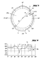
- Fig. 2 ein von der Bildananlysevorrichtung der Fig. 1 dargestelltes Bild des Prüflings mit schematisch eingezeichneten flächenhaft wiedergegebenen Fehlern;
- Fig. 3 ein Positionierschema bei der Bildanalyse eines als Kontaktlinse ausgebildeten Prüflings;
- Fig. 4 eine Zoneneinteilung an einem als Kontaktlinse ausgebildeten Prüfling;
- Fig. 5 ein Erfassungsschema für Randfehler an einem als Kontaktlinse ausgebildeten Prüfling;
- Fig. 6 eine Kurvendarstellung der gemäß Fig. 5 erfaßten Randfehler;
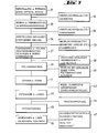
- Fig. 7 schematisch verschiedene Herstellungsschritte bei der Herstellung einer Kontaktlinse mit integrierten automatischen Prüfschritten;
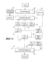
- Fig. 8 schematisch verschiedene Herstellungsschritte eines weiteren Herstellungsverfahrens für Kontaktlinsen mit integrierten automatischen Prüfschritten;
- Fig. 9 eine für eine Endprüfung mit Hilfe des erfindungsgemäßen verfahrens geeignete verpackung, insbesondere für Kontaktlinsen in Draufsicht;
- Fig. 10 eine schnittbildliche Darstellung der in Fig. 9 gezeigten verpackung;
- Fig. 11 ein Blockschaltbild für eine in Fig. 1 gezeigte Bildanalyseeinrichtung; und
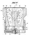
- Fig. 12 einen Längsschnitt einer Beleuchtungseinrichtung.
- 1 schematically shows an image analysis device which is an embodiment of the invention;
- FIG. 2 shows an image of the test specimen, represented by the image analysis device of FIG. 1, with schematically drawn-in errors.
- 3 shows a positioning scheme in the image analysis of a test piece designed as a contact lens;
- 4 shows a zoning on a test specimen designed as a contact lens;
- 5 shows a detection scheme for edge defects on a test piece designed as a contact lens;
- FIG. 6 shows a graph of the marginal errors detected according to FIG. 5;
- 7 schematically shows different manufacturing steps in the manufacture of a contact lens with integrated automatic test steps;
- 8 schematically shows different manufacturing steps of a further manufacturing method for contact lenses with integrated automatic testing steps;
- 9 shows a packaging suitable for a final inspection using the method according to the invention, in particular for contact lenses, in a top view;
- FIG. 10 shows a sectional representation of the packaging shown in FIG. 9;
- Fig. 11 is a block diagram for an image analysis device shown in Fig. 1; and
- 12 shows a longitudinal section of an illumination device.
In der Fig. 1 ist eine vorrichtung gezeigt, die zur Prüfung von optischen Bauteilen dient. Ein zu prüfendes Bauteil 6 befindet sich auf einer Halte- und Transporteinrichtung 8. Eine Beleuchtungseinrichtung 1 beinhaltet einen Kontrastbildgeber 5, der als Dunkelfeldbeleuchtungseinrichtung ausgebildet sein kann. Mit Hilfe einer Lichtquelle 18, deren Licht mehrfach reflektiert und gestreut wird, wird das zu prüfende Bauteil 6 vor einem dunklen Hintergrund 19 beleuchtet.1 shows a device which is used for testing optical components. A
Für die Verarbeitung des auf diese Weise dargestellten Kontrastbildes bzw. Dunkelfeldbildes ist eine Bildverarbeitungseinrichtung 2 vorgesehen. Diese Bildverarbeitungseinrichtung 2 umfaßt eine Bildaufnahmeeinrichtung 3 mit einem Bildsensor 4. Es kann sich hier beispielsweise um eine videokamera handeln, deren Bildsensor 4 als CCD ausgebildet ist.An
Die videokamera kann an einen nicht näher dargestellten Monitor angeschlossen sein, auf welchem das flächenhafte Kontrastbild sichtbar gemacht werden kann. Wenn der Bildsensor als CCD ausgebildet ist, hat man automatisch aufgrund des CCD-Aufbaus eine Bildaufteilung in Bildelemente (Pixel), beispielsweise in 500 x 700, d.h. es ergibt sich hier von selbst eine Bildaufteilung. Mit Hilfe einer Lese-und Umsetzereinrichtung 7 können die einzelnen Bildelemente des Kontrastbildes abgetastet und in Binärsignale umgewandelt werden, die dann abgespeichert und weiterverarbeitet werden, wie das im folgenden erläutert wird.The video camera can be connected to a monitor, not shown, on which the areal contrast image can be made visible. If the image sensor is designed as a CCD, the CCD structure automatically divides the image into picture elements (Pixels), for example in 500 x 700, which means that the image is divided automatically. With the aid of a reading and converting device 7, the individual picture elements of the contrast image can be scanned and converted into binary signals, which are then stored and processed, as will be explained in the following.
Ein Ausführungsbeispiel für ein Kontrastbild 12 eines Prüflings ist in Form eines Binärbildes in Fig. 2 dargestellt. Es kann sich hier beispielsweise um das Kontrastbild 12 einer zu prüfenden Kontaktlinse handeln. Fehler auf der Oberfläche des Prüflings 6 oder eingeschlossene Fehler sind in dem Kontrastbild 12 flächenhaft dargestellt. Es handelt sich hier beispielsweise um die flächenhaft dargestellten Fehler 13, 14, 15, 16 und 17. Diese können Löcher, Luftblasen, Einschlüsse, anhaftende Bruchstücke usw. darstellen.An exemplary embodiment of a
Wie die Fig. 2 zeigt, werden diese flächenhaft dargestellten Fehler bzh. Fehlerflächen in einzelne Bildelemente, sogenannte Pixel, unterteilt. Eine solche Unterteilung kann beispielsweise mit Hilfe des Bildsensors 4 (CCD) in Zusammenwirkung mit der Lese- und Umsetzereinrichtung 7 durchgeführt werden.As shown in FIG. 2, these areal errors or Defect areas are divided into individual picture elements, so-called pixels. Such a division can be carried out, for example, with the aid of the image sensor 4 (CCD) in cooperation with the reading and converting device 7.
An die Einrichtung 7 ist eine Bildanalyseeinrichtung 9 (Bildeinteilung, Pixelauszählung, Pixelvergleich) angeschlossen. Diese erfasst die Anzahl der Pixel, beispielsweise durch Zählen. Dazu kann die Bildanalyseeinrichtung 9 eine entsprechend ausgebildete Zähleinrichtung (Pixelzähler 23 in Fig.11) aufweisen.An image analysis device 9 (image division, pixel counting, pixel comparison) is connected to the device 7. This records the number of pixels, for example by counting. For this purpose, the
Unter Bezugnahme auf die Fig. 11, die schematisch ein Blockschaltbild für die in der Bildanalyseeinrichtung 9 enthaltenen Funktionseinheiten darstellt, wird die Arbeitsweise der Bildanalyseeinrichtung 9 erläutert.The operation of the
Ein Bilderfassungsspeicher 20 erhält von der Ausleseeinrichtung 7 (Fig. 1) das von der Videokamera bzw. dem Bildsensor 4 der Bildaufnahmeeinrichtung 3 erfasste Bild des zu prüfenden Bauteils 6. Dieses Bild kann die in der Fig. 2 dargestellte Form aufweisen. Um für die Qualitätskontrolle das zu prüfende Bauteil 6 zentriert und richtig in der Bilderzeugungseinrichtung 1 und Bildverarbeitungseinrichtung 2 anzuordnen, ist eine Ausricht- und Zentriersteuereinrichtung 22 mit der Bilderfassungseinrichtung 20 verbunden. Die Steuereinrichtung 22 steuert die Halte- und Transporteinrichtung 8 (Fig.l) entsprechend an, wenn der Prüfling 6 nicht zentriert angeordnet ist. Zur Positionierung der Linse in dem in der Fig. 3 dargestellten quadratischen Feld wird zunächst der Linsenrand erfaßt welcher die äußere Begrenzung des Suchfeldes darstellt Bei der Positionierung wird dann von "außen nach innen" gesucht.An
Da Kontaktlinsen üblicherweise eine Gravur aufweisen, ist es erforderlich, bei der Prüfung diese Gravur auszusparen, da sie sonst eine Fehleranzeige veranlassen würde. Hierzu ist das in Fig. 3 dargestellte quadratische Feld in acht Sektoren unterteilt. Beim dargestellten Ausführungsbeispiel erfolgt die Positionierung so, daß die Gravur hälftig in den beiden Sektoren II und III angeordnet ist. Die eine Hälfte der Gravur befindet sich links von der Zwölf-Uhr-Stellung, und die andere Hälfte der Gravur befindet sich rechts von der Zwölf-Uhr-Stellung, wobei beide Gravurhälften den gleichen Abstand zur Zwölf-Uhr-Stellung aufweisen. Damit der Prüfling 6 richtig positioniert wird, kann die Halte- und Transporteinrichtung 8 eine x-y-verschiebeeinrichtung aufweisen.Since contact lenses usually have an engraving, it is necessary to omit this engraving during the test, otherwise it would cause an error display. For this purpose, the square field shown in FIG. 3 is divided into eight sectors. In the illustrated embodiment, the positioning is carried out so that the engraving is arranged in half in the two sectors II and III. One half of the engraving is to the left of the twelve o'clock position and the other half of the engraving is to the right of the twelve o'clock position, with the two halves of the engraving being the same Be clear of the twelve o'clock position. So that the
Wenn das zu prüfende Bauteil 6 aus verschiedenen Zonen bzw. Teilen gebildet wird, für die unterschiedliche Qualitäts-standards ausreichen oder auch gefordert werden, ist es von vorteil, eine entsprechende Zoneneinteilung am erfaßten Bild (Fig. 2) des zu prüfenden Bauteils 6 vorzunehmen.If the
In der Fig. 4 ist beispielsweise für eine Kontaktlinse eine derartige Zonenaufteilung schematisch dargestellt. Durch einen Bereich, der durch einen Radius r1 erfaßt ist, ist eine Optikzone OZ der Kontaktlinse festgelegt. Durch Radien r2 und r3 ist eine auszublendende Schriftzone im Gravur-winkelbereich festgelegt.Such a zone division is shown schematically for a contact lens in FIG. 4. An optical zone OZ of the contact lens is defined by an area which is covered by a radius r1. Radii r2 and r3 define a font zone to be hidden in the engraving angle range.
Durch einen Bereich zwischen Radien r1 und r4 ist eine Lentikularzone LZ definiert, und durch den Radius r4 ist der Rand R der Linse definiert.A lenticular zone LZ is defined by a region between radii r1 and r4, and the edge R of the lens is defined by the radius r4.
Für die optische OZ und für die Lentikularzone LZ lassen sich unterschiedliche Fehlergrenzen festsetzen, wobei die Fehlergrenze für die optische Zone OZ niedriger festzusetzen ist als die Fehlergrenze für die Lentikularzone LZ. Auch für den Rand R kann eine Randfehlergrenze festgelegt werden; beispielsweise dürfen die Längs- und/oder Querabmessungen nicht größer als 50 µm sein. Die Fehlergrenze kann jedoch bei der Erfindung auch noch niedriger, beispielsweise bei 20 µm, angesetzt werden. Dies gilt auch für die Fehlergrenzen im optischen Bereich OZ und im Lentikularbereich LZ. Je nachdem, wie hoch die Qualität der Kontaktlinse bzw. des zu prüfenden Bauteils 6 sein soll, wird die Fehlergrenze (Fehlerschwelle) angesetzt.Different error limits can be set for the optical OZ and for the lenticular zone LZ, the error limit for the optical zone OZ being set lower than the error limit for the lenticular zone LZ. An edge error limit can also be set for the edge R; for example, the longitudinal and / or transverse dimensions must not be larger than 50 µm. However, the error limit can also be set lower in the invention, for example at 20 μm. This also applies to the error limits in the optical area OZ and in the lenticular area LZ. Depending on how high the quality of the contact lens or the one to be checked
Wärend für die flächenhaften Zonen des Bildes entsprechende zugeordnete Fehlerschwellen festgelegt sind, läßt sich für den Kontaktlinsenrand R nach dem in den Figuren 5 und 6 dargestellten Prinzip eine Fehlererfassung durchführen. Es können hier verschiedene Kriterien einzeln oder insgesamt berücksichtigt werden. Ein Kriterium kann sein, ob der Radius an einer bestimmten Randstelle von einem mittleren Radius Rm über eine vorgegebene Radiusabweichung Δ Rg/2 hinaus abweicht oder nicht. Ferner kann als Kriterium berücksichtigt werden, ob diese zu starken Radiusabweichungen in ihrer Gesamtheit eine bestimmte Schwelle überschreiten oder nicht. Schliesslich kann noch als Kriterium untersucht werden, ob die Kurvenform des Randes stark von einer Kreisform abweicht oder nicht, wie das beispielsweise zwischen den beiden Kurventeilen C1 und C2 bzw. zwischen den Kurventeilen C3 und C4 in Fig. 5 dargestellt ist. Fig. 6 zeigt beispielsweise, dass etwa bei 150° eine starke Radiusabweichung vorhanden ist. In Fig. 5 ist diese mit R1 - R2 dargestellt. Aus Fig. 6 ist auch die starke Abweichung des Randes von der Kreisform zwischen den Kurventeilen C3 und C4 erkenntlich.Ferner ist aus der Fig. 6 auch eine starke Radiusabweichung im Bereich von etwa 260° bis 300°erkennbar.While corresponding assigned error thresholds are defined for the planar zones of the image, an error detection can be carried out for the contact lens edge R according to the principle shown in FIGS. 5 and 6. Various criteria can be taken into account here individually or as a whole. A criterion can be whether or not the radius at a certain edge point deviates from a mean radius Rm beyond a predetermined radius deviation Δ Rg / 2. Furthermore, it can be taken into account as a criterion whether or not all of these excessive radius deviations exceed a certain threshold. Finally, it can also be examined as a criterion whether the curve shape of the edge deviates strongly from a circular shape or not, as is shown, for example, between the two curve parts C1 and C2 or between the curve parts C3 and C4 in FIG. 5. 6 shows, for example, that there is a large radius deviation at approximately 150 °. In Fig. 5 this is shown with R1 - R2. 6 also shows the large deviation of the edge from the circular shape between the curve parts C3 and C4. Furthermore, a large radius deviation in the range of approximately 260 ° to 300 ° can also be seen in FIG.
Die angesprochenen Fehler lassen sich in der Bildanalyseeinrichtung 9 (Fig. 1) mit Hilfe einer Speichereinrichtung 21 (Fig. 11), in welcher die in Fig. 4 gezeigte Zoneneinteilung festgelegt ist, in Zusammenwirkung mit Grenzwertspeichern erfassen. Beispielsweise sind für die optische Zone OZ ein Grenzwertspeicher 27, für die Lentikularzone LZ ein Grenzwertspeicher 28 und für den Rand R ein dritter Grenzwertspeicher 29 vorgesehen. Für die entsprechenden Zonen sind zugeordnete Pixelzähler 23 vorhanden. Die Pixelzähler, welche Werte für die Fehlergrössen in den jeweiligen Zonen angeben, liefern diese Werte an Vergleicher 24, 25 und 26, die mit den beschriebenen zugeordneten Grenzwertspeichern 27, 28 und 29 verbunden sind. Das Vergleichsergebnis kann in einem Zwischenspeicher 30 für die jeweiligen Zonen abgelegt werden und gegebenenfalls zusammen mit dem erfassten Bild im Bilderfassungsspeicher 20 an einem Monitor wiedergegeben werden.The errors addressed can be recorded in the image analysis device 9 (FIG. 1) with the aid of a memory device 21 (FIG. 11), in which the zone division shown in FIG. 4 is defined, in cooperation with limit value memories. For example, a
Ferner wird in Abhängigkeit von den jeweiligen Vergleichsergebnissen der Vergleicher 24, 25 und 26 entweder über den Zwischenspeicher 30 oder direkt ein Aussortierer 11 (Fig. 1) angesteuert. Dieser Aussortierer 11 ist mit der Halte- und Transporteinrichtung 8 verbunden bzw. in Wirkverbindung. Dies ist durch eine strichlierte Linie in Fig. 1 schematisch dargestellt. Das zu prüfende Bauteil 6 wird dann in Abhängigkeit auf der Halte- und Transporteinrichtung 8 belassen, wenn es gemäß dem Vergleichsergebnis den Qualitätsanforderungen genügt. Das zu prüfende Bauteil 6 wird dann in die nächste Bearbeitungsstation übergeführt. Falls das Bauteil 6 den Qualitätsanforderungen nicht genügt, wird es durch die Wirkung des Aussortierers 11 aus der Halte- und Transporteinrichtung 8 entfernt.Furthermore, depending on the respective comparison results, the
Ein Ausführungsbeispiel der Einrichtung zur Beleuchtung des Prüfobjekts, z.B. zur Beleuchtung der Kontaktlinse, ist in Fig. 12 dargestellt. Dort ist mit 110 ein zentraler erster Reflektorkörper bezeichnet. Der erste Reflektorkörper 110 weist eine ebene, obere Stirnfläche 112 auf. Die obere Stirnfläche 112 erstreckt sich senkrecht zu einer Systemachse 114. Anschliessend an die Stirnfläche 112 weist der Reflektorkörper 110 eine zu der Systemachse 114 koaxiale, zylindrische Mantelfläche 116 auf. Auf der Unterseite bildet der Reflektorkörper 110 einen konvex-konischen, ersten Reflektor 118. Die Konusachse des Reflektors 118 fällt mit der Systemachse 114 zusammen.An exemplary embodiment of the device for illuminating the test object, for example illuminating the contact lens, is shown in FIG. 12. There, 110 denotes a central first reflector body. The
Unterhalb des Reflektorkörpers 110 ist auf der Systemachse 114 eine Lichtquelle 120 angeordnet. Von der Lichtquelle 120 fällt ein zentrales Lichtbündel 122 auf den konvexkonischen, ersten Reflektor 118. Das Lichtbündel 122 wird von dem ersten Reflektor 118 radial auseinandergefächert. In der Zeichnung sind die Randstrahlen 124 und der längs der Systemachse 114 verlaufende Zentralstrahl 126 des Lichtbündels 122 vor und nach der Reflexion an dem ersten Reflektor 118 dargestellt.A
Das radial auseinandergefächerte Lichtbündel 122 fällt auf einen zweiten Reflektor 128. Der zweite Reflektor 128 ist konkav-zylindrisch und koaxial zu der Systemachse 114. Der zweite Reflektor 128 ist an einem zweiten Reflektorkörper 130 angebracht. Der zweite Reflektorkörper weist eine ringförmige, ebene Stirnfläche 132 auf. An die Stirnfläche 132 schliesst sich innen der zylindrische Reflektor 128 an. Auf der Aussenseite weist der Reflektorkörper 130, anschliessend an die Stirnfläche 132, eine zylindrische Mantelfläche 134 koaxial zu dem Reflektor 128 auf. Anschliessend an die zylindrische Mantelfläche 134 bildet der Reflektorkörper 130 einen konischen Abschnitt 136 An den konischen Abschnitt 136 schliesst sich ein zylindrischer, mit einem Aussengewinde versehener Abschnitt 138 an. Auf der Innenseite schliesst sich an den zylindrischen Reflektor 128 ein konischer Abschnitt 140 an. Unten bildet der Reflektorkörper 130 eine untere Stirnfläche 142 mit einer zentralen Öffnung 144. Durch diese Öffnung 144 ragt die Lichtquelle 120 in das Innere des Reflektorkörpers 130.The radially fanned
Auf der oberen Stirnfläche 132 des Reflektorkörpers 130 liegt eine klar-transparente Platte 146, welche mit ihrer planen Oberseite eine Auflage 148 für die Prüfobjekte bildet. Die von der Auflage 148 definierte Auflageebene ist senkrecht zur Systemachse 114 und dementsprechend parallel zu der Stirnfläche 112 des ersten Reflektorkörpers 110. Die Platte 148 ist oben und unten mit reflexmindernden Schichten 150, 152 versehen. Der konkav-zylindrische zweite Reflektor 128 reflektiert das radial auseinandergefächerte Lichtbündel 122 so, dass es fast streifend in der Mitte der Auflage 148 in einem Lichtfleck gesammelt wird.On the
Der zweite Reflektorkörper 130 ist mit dem mit Aussengewinde versehenen Abschnitt 138 in einen mit einem Innengewinde 154 versehenen, topfförmigen Gehäuseteil 156 eingeschraubt. Der Gehäuseteil 156 trägt innen auf der Systemachse 114 einen Socke 158 für die Lichtquelle 120. Ausserdem sind im Boden des topfförmigen Gehäuseteils 156 Tragstangen 160 gehaltert, welche den ersten Reflektorkörper 110 tragen. Die Tragstangen 160 sind durch fluchtende Durchbrüche im Boden des Gehäuseteils 156 sowie durch eine Querbohrung 162 von Klemmschrauben 164 geführt. Die Klemmschrauben 164 sitzen in radialen Gewindebohrungen 166 im Boden des Gehäuseteils 156 zwischen den besagten fluchtenden Durchbrüchen. Die Klemmschrauben 164 können gelöst werden. Dann sind die Tragstangen 160 und damit der erste Reflektorkörper 110 relativ zu dem topfförmigen Gehäuseteil 156 höhenverstellbar. Es ist so eine Justage des Reflektorkörpers 110 relativ zu der Lichtquelle 120 möglich. Der Gehäuseteil 156, die Lichtquelle 120 und der erste Reflektorkörper 110 bilden eine zusammenhängende Baugruppe 170, die als Ganzes über das Innengewinde 154 und den mit Aussenge-winde versehenen Abschnitt 138 des zweiten Reflektorkörpers 130 relativ zu dem zweiten Reflektorkörper 130 und damit zü dem zweiten Reflektor 128 und der Auflage 148 in Richtung der Systemachse 114 verstellbar ist (oder umgekehrt ).The
Durch diese Verstellung wird einmal der in der Auflageebene erzeugte Lichtfleck an die Abmessungen der Prüfobjekte angepasst. Weiterhin kann das Gerät so eingestellt werden, dass sich optimaler Kontrast für die Fehlererkennung ergibt.With this adjustment, the light spot generated in the support plane is adapted to the dimensions of the test objects. Furthermore, the device can be set so that there is optimal contrast for error detection.
Die Reflektoren 118 und 128 können spiegelnd ausgebildet sein. Die Oberflächen des ersten und des zweiten Reflektors 118 bzw. 128, können aber auch teildiffus-reflektierend ausgebildet sein.The
Eine alternative Lösung kann darin bestehen, dass die Lichtquelle ein Kaltleiter-Ringlicht ist. Die Einstellbarkeit der Beleuchtungsgeometrie kann dann darin bestehen, dass die Abstrahlcharakteristik des Kaltleiter-Ringlichts an die Geometrie des Prüfobjekts anpassbar ist.An alternative solution can be that the light source is a PTC ring light. The adjustability of the lighting geometry can then consist in that the radiation characteristic of the PTC thermistor ring light can be adapted to the geometry of the test object.
Anhand der Figungen 7 und 8 wird nun noch an zwei verschiedenen Herstellungsverfahren für Kontaktlinsen demonstriert, wie die erfindungsgemässe Bildanalyse in Kombination mit anderen Bildverarbeitungsverfahren in den Herstellungsprozeß bei verschiedenen Herstellungsstuffen bzw. -schritten integriert werden kann, so -daß ein automatischer Ablauf der Gesamtherstellung der Kontaktline erreicht wird.With the help of FIGS. 7 and 8, two different manufacturing methods for contact lenses will now be used to demonstrate how the image analysis according to the invention in combination with other image processing methods can be integrated into the manufacturing process at different manufacturing stages or steps, so that an automatic sequence of the entire manufacturing of the contact line is achieved.
In der Fig. 7 ist ein sogenanntes Fullmold-verfahren, welches ein Formgießen der Kontaktlinse beinhaltet, in seinen einzelnen Schritten dargestellt mit integrierter automatischer Prüfung mit Hilfe der erfindungsgemäßen Bildanalyse. Fullmoldverfahren sind bekannt (z. B. EP 0 367 513 und Wo 87/04390).FIG. 7 shows a so-called full mold process, which includes molding the contact lens, shown in its individual steps with integrated automatic testing using the image analysis according to the invention. Full mold processes are known (e.g. EP 0 367 513 and Wo 87/04390).
In einem Herstellungsschritt 31 werden die Formeinsätze (optical tools), die aus hochwertigen Metallen/Legierungen bestehen, beispielsweise durch spanende Bearbeitung hergestellt. Hier kann bereits ein erster Prüfschritt 32 mit Hilfe einer Bildanalyse durchgeführt werden. Dieser Prüfschritt kann die Oberflächenqualität der Formeinsätze und die Geometrie der Formeinsätze prüfen. Anschließend werden in einem Schritt 33 die Formeinsätze in ein Spritzgießwerkzeug eingesetzt. Auch hier kann eine optische Prüfung mit Hilfe einer Bildanalyse in einem Prüfschritt 35 zur Überprüfung der Oberflächenqualität und der Einbaumaße durchgeführt werden.In a
Hieran schließt sich die Herstellung der Kunststoffformen, d. h. der beiden Formhälften (Molds), in denen die Kontaktlinse durch Formgießen hergestellt werden soll, an (Herstellungsschritt 34). Auch hier kann ein Prüfschritt 36 mit Bildanalyse integriert werden, so daß die Oberflächenqualität, die Geometrie (verzug und dgl.) sowie Staubfreiheit der hergestellten Formhälften überprüft werden kann. Hieran schließt sich das Dispensieren des Polymerisationsansatzes für das Kontaktlinsenmaterial und das Schließen der beiden Formhälften in einem Schritt 37 an. Hier kann ebenfalls ein Prüfschritt 38 integriert werden, bei dem mit Hilfe der erläuterten Bildanalyse das richtige Schließen und das Vorhandensein von Luftblasen ermittelt werden kann.This is followed by the production of the plastic molds, ie the two mold halves (molds) in which the contact lens is to be produced by molding (production step 34). Here, too, a test step 36 with image analysis can be integrated, so that the surface quality, the geometry (distortion and the like) and the absence of dust in the mold halves produced can be checked. This is followed by dispensing the polymerization batch for the contact lens material and closing the two mold halves in a
Es erfolgt dann in einem Schritt 39 die Polymerisation des Kontaktlinsenmaterials, das von den beiden Formhälften umschlossen ist. Hierbei kann in einem Prüfschritt 40 bei geschlossener Form, die lichtdurchlässig ist, nicht nur der Ablauf der Polymerisation, sondern auch der Polymerisationsschwund des polymerisierten Materials und eine geeignete Nachstellung der beiden Formhälften in diesem Zusammenhang überwacht werden, Gegebenenfalls kann in Abhängigkeit vom Ergebnis der Bildanalyse und in Abhängigkeit vom festgestellten Polymerisationsschwund das Nachstellen der beiden Formhälften zur Kompensierung des Polymerisationsschwundes gesteuert werden.The contact lens material, which is enclosed by the two mold halves, is then polymerized in a
In einem weiteren Fertigungsschritt 41 erfolgt das Öffnen der beiden Formhälften. Im Rahmen eines integrierten Prüfschrittes 42 kann hier eine Zwischenkontrolle durchgeführt werden im Hinblick auf grobe Fehler, wie Risse, Ausbrüche und dgl. am hergestellten Linsenkörper.In a
Im anschließenden Fertigungsschritt 43 wird die Kontaktlinse aus der Form entnommen, und es kann an der Kontaktlinse mit Hilfe der erläuterten Bildanalyse in einem Prüfschritt 44 eine Trockenprüfung durchgeführt werden. Hieran kann sich in einem Fertigungsschritt 45 die Hydratisierung des Linsenkörpers anschließen. In einem weiteren Fertigungsschritt 46 wird die Linse (trocken oder hydratisiert) in Gläschen oder in sogenannten Foilpacks 68, welche in den Figuren 9 und 10 dargestellt sind, eingebracht.In the
Anschließend kann in einem Prüfschritt 47 überprüft werden, ob die Linse in den Aufbewahrungsbehälter 69 eingebracht wurde. Dies erfolgt im Rahmen einer sogenannten Anwesenheitskontrolle. Ausserdem kann überwacht werden, ob der Flüssigkeitsstand im Aufbewahrungsbehälter stimmt. Ferner kann die Sauberkeit der Aufbewahrungsflüssigkeit sowie der Linse selbst überwacht werden. Ferner können Linsenqualität und Brechkraft einer Endprüfung unterzogen werden. Die im Prüfschritt 47 erläuterten Prüfungen können mit Hilfe der oben beschriebenen Bildanalyse durchgeführt werden. Anschließend werden die Behälter (Fig. 9, 10) mit den Deckfolien 71 durch Schweißen verschlossen.It can then be checked in a
In der Fig. 8 ist ein Drehverfahren erläutert, mit dem ebenfalls eine Kontaktlinse hergestellt werden kann. Bei diesem Drehverfahren wird in einem Fertigungsschritt 48 ein Button von einer Stange aus Kontaktlinsenmaterial abgeschnitten und in ein Spannfutter einer Drehmaschine eingesetzt. Drehautomaten sind bekannt. Es wird hierzu beispielsweise auf die deutsche Patentschrift 31 10 624 verwiesen. In einem Prüfschritt 49 kann beispielsweise mit Hilfe der oben beschriebenen Bildanalyse der Button im Hinblick auf Materialeinschlüsse, auf seine Abmessungen (Trimmaße) hin überprüft werden. In einem Fertigungsschritt 50 wird durch Drehen mit Hilfe eines Drehwerkzeugs im Drehautomaten eine Innenkurve IK am Button hergestellt. In einem nachfolgenden Prüfschritt 51 kann durch Bildanalyse das Drehbild und die Oberflächenqualität und gegebenenfalls auch die Geometrie, für welches auch ein bekanntes Moiree-verfahren zum Einsatz gebracht werden kann, überprüft werden.8 illustrates a turning method with which a contact lens can also be produced. In this turning method, a button is cut from a rod made of contact lens material in a
In einem weiteren Fertigungsschritt 52 erfolgt das Polieren der Innenkurve IK. Gegebenenfalls kann in einem Prüfschritt 53 das Polierbild, die Oberflächenqualität und noch einmal die Geometrie der Innenkurve überprüft werden.In a
Es erfolgt dann das Aufritten des Buttons auf eine Spindel des Drehautomaten in einem Fertigungsschritt 54. Dabei wird der Button mit seiner Innenkurve auf die Spindel aufgekittet. Auch hierbei können in einem Prüfschritt 55 mit Hilfe einer optischen Bildanalyse die Qualität und die Abmessungen der Wachsschicht, welche zum Aufkitten dient, sowie der Rundlauf und eine Scheitelpunktbestimmung durchgeführt werden.The button is then treaded onto a spindle of the automatic lathe in a
Anschliessend wird in einem Fertigungsschritt 56 die Aussenkurve AK gedreht. Das Drehbild, die Geometrie sowie die Mittendicke der fertiggestellten Linse können in einem Prüfschritt 57 überprüft werden.The outer curve AK is then rotated in a
Es erfolgt dann in einem Fertigungsschritt 58 das Polieren der Aussenkurve AK. In einem Prüfschritt 59 können dann das Polierbild, die Geometrie und die Mittendicke der Kontaktlinse überprüft werden. Der Prüfschritt 57 kann in diesem Falle auch entfallen.The outer curve AK is then polished in a
In einem Fertigungsschritt 60 wird die Kontaktlinse von der Kalotte des Drehautomaten abgekittet. In einem Fertigungsschritt 61 erfolgt die Randbearbeitung der Kontaktlinse. In einem sich anschließenden Fertigungsschritt 62 erfolgt die Reinigung der Kontaktlinse. An die Reinigung der Kontaktlinse kann sich ein Prüfschritt 63 anschließen, in welchem mit Hilfe der Bildanalyse (z.B. Fig. 1) eine Trockenprüfung der Kontaktlinse durchgeführt wird.In a
Hieran schließt sich als Fertigungsschritt 64 die Gravur der Kontaktlinse an. In diese wird dann die beispielsweise aus den Figuren 3 und 4 ersichtliche Gravur in den Kontaktlinsekörper eingeprägt. Hieran schließt sich dann als Fertigungsschritt 65 eine Oberflächenbehandlung der Kontaktlinse an. Diese hat insbesondere den Vorteil, daß die Oberfläche der Linse für die Tränenflüssigkeit benetzbar gemacht wird. In einem Prüfschritt 66 kann dann die Prüfung der Benetzbarkeit ebenfalls mit Hilfe der Bildanalyse (z.B. Fig.1) durchgeführt werden. Durch die Bildanalvse läßtsich nämlich feststellen, ob auf der Oberfläche Tröpfchenbildung erfolgt oder ob die Linsenoberfläche von der Flüssigkeit flächig benetzt wird.This is followed by the engraving of the contact lens as
In einem weiteren Fertigungsschritt 67 erfolgt das Einlegen der Linse beispielsweise in Foilpacks (Fig. 9, 10). Hieran kann sich dann, wei bei dem in Fig. 7 dargestellten Fullmold-Verfahren, ein Prüfschritt anschließen, der dem Prüfschritt 47 entspricht. Anschließend erfolgt das Aufschweißen der Deckfolien auf die Behälter.In a
Aus obiger Erläuterung, insbesondere im Zusammenhang mit den Figuren 7 und 8, ergibt sich, daß mit Hilfe der optischen Bildanalyse eine vollständige Überwachung und damit 100 %ige Automatisierung bei der Fertigung von optischen Bauteilen erreicht werden kann. Dies gilt insbesondere bei der Herstellung von Kontaktlinsen. Hierdurch wird die gewünschte Produktqualität durch ständige Überwachung (in-process-Kontrolle) des gesamten Fertigungsablaufes garantiert, so daß unter Umständen auf eine Endkontrolle verzichtet werden kann. vor allem für in großen Stückzahlen herzustellende Kontaktlinsen (Wegwerflinsen) ist eine solche Überwachung von vorteil. Die durch die Erfindung gewährleistete Qualitätskontrolle richtet sich nach vorgebbarem Qualitätsstandard und ist damit eine reproduzierbare und objektive Qualitätskontrolle.From the above explanation, in particular in connection with FIGS. 7 and 8, it follows that complete monitoring and thus 100% automation in the manufacture of optical components can be achieved with the aid of optical image analysis. This applies particularly to the manufacture of contact lenses. As a result, the desired product quality is guaranteed by constant monitoring (in-process control) of the entire production process, so that, under certain circumstances, a final inspection can be dispensed with. Such monitoring is particularly important for contact lenses (disposable lenses) to be produced in large quantities advantageous. The quality control guaranteed by the invention is based on a specifiable quality standard and is therefore a reproducible and objective quality control.
Claims (23)
dadurch gekennzeichnet,
daß von dem jeweiligen zu prüfenden Bauteil ein flächenhaftes Kontrastbild hergestellt wird und die Bildfläche der jeweiligen sichtbar gemachten Fehler bestimmt und mit einem oder mehreren Grenzwerten verglichen wird.Method for testing optical components, in which an image is produced of the component to be inspected and errors in the depicted object are detected by image analysis,
characterized,
that an areal contrast image is produced from the respective component to be tested and the image area of the respective defects made visible is determined and compared with one or more limit values.
Applications Claiming Priority (4)
| Application Number | Priority Date | Filing Date | Title |
|---|---|---|---|
| CH403290 | 1990-12-19 | ||
| CH4032/90 | 1990-12-19 | ||
| DE19914124003 DE4124003C2 (en) | 1991-07-19 | 1991-07-19 | Lighting device for illuminating clear-transparent test objects, for examining the test objects for defects |
| DE4124003 | 1991-07-19 |
Publications (2)
| Publication Number | Publication Date |
|---|---|
| EP0491663A1 true EP0491663A1 (en) | 1992-06-24 |
| EP0491663B1 EP0491663B1 (en) | 1996-01-10 |
Family
ID=25694472
Family Applications (1)
| Application Number | Title | Priority Date | Filing Date |
|---|---|---|---|
| EP19910810978 Expired - Lifetime EP0491663B1 (en) | 1990-12-19 | 1991-12-13 | Procedure and apparatus for the examination of optical components, particularly ophthalmic components, and device for the illumination of transparent objects under examination |
Country Status (13)
| Country | Link |
|---|---|
| EP (1) | EP0491663B1 (en) |
| JP (1) | JPH04321186A (en) |
| KR (1) | KR100202215B1 (en) |
| AT (1) | ATE132971T1 (en) |
| AU (1) | AU649291B2 (en) |
| CA (1) | CA2057832A1 (en) |
| DE (1) | DE59107249D1 (en) |
| DK (1) | DK0491663T3 (en) |
| ES (1) | ES2082178T3 (en) |
| GR (1) | GR3018639T3 (en) |
| HK (1) | HK1003125A1 (en) |
| IE (1) | IE70436B1 (en) |
| PT (1) | PT99855B (en) |
Cited By (31)
| Publication number | Priority date | Publication date | Assignee | Title |
|---|---|---|---|---|
| EP0604178A1 (en) * | 1992-12-21 | 1994-06-29 | JOHNSON & JOHNSON VISION PRODUCTS, INC. | Illumination system for ophthalmic lens inspection |
| EP0599335A3 (en) * | 1992-11-25 | 1994-07-13 | Fuji Electric Co Ltd | Cylindrical container inner surface tester. |
| EP0604180A3 (en) * | 1992-12-21 | 1994-09-14 | Johnson & Johnson Vision Prod | Ophthalmic lens inspection system and method. |
| EP0605171A3 (en) * | 1992-12-21 | 1994-09-14 | Johnson & Johnson Vision Prod | Lens inspection system. |
| EP0605990A3 (en) * | 1992-12-21 | 1994-09-21 | Johnson & Johnson Vision Prod | Illumination and imaging subsystems for a lens inspection system. |
| EP0604173A3 (en) * | 1992-12-21 | 1994-11-09 | Johnson & Johnson Vision Prod | Support device for ophthalmic lenses. |
| EP0607692A3 (en) * | 1992-12-21 | 1994-11-17 | Johnson & Johnson Vision Prod | Ophthalmic lens inspection process. |
| EP0604174A3 (en) * | 1992-12-21 | 1995-02-15 | Johnson & Johnson Vision Prod | Method and device for automatic inspection of ophthalmic lenses. |
| EP0604179A3 (en) * | 1992-12-21 | 1995-02-15 | Johnson & Johnson Vision Prod | Method and device for inspecting ophthalmic lenses. |
| US5412203A (en) * | 1991-07-15 | 1995-05-02 | Fuji Electric Co., Ltd. | Cylindrical container inner surface tester |
| EP0686842A3 (en) * | 1994-06-10 | 1997-05-07 | Johnson & Johnson Vision Prod | Lens inspection system and method |
| EP0686841A3 (en) * | 1994-06-10 | 1997-05-07 | Johnson & Johnson Vision Prod | System and method for inspecting lenses |
| EP0660098A3 (en) * | 1993-12-27 | 1997-06-04 | Menicon Co Ltd | Visual inspection method and apparatus for contact lenses. |
| US5801822A (en) * | 1997-02-06 | 1998-09-01 | Pbh, Inc. | Ophthalmic lens inspection system |
| US5818573A (en) * | 1997-02-06 | 1998-10-06 | Pbh, Inc. | Opthalmic lens inspection system |
| EP0766063A3 (en) * | 1995-09-29 | 1998-10-28 | JOHNSON & JOHNSON VISION PRODUCTS, INC. | Lens parameter measurement using optical sectioning |
| CN1040634C (en) * | 1992-12-21 | 1998-11-11 | 庄臣及庄臣视力产品有限公司 | Ophthalmic lens package |
| WO1999032869A1 (en) * | 1997-12-19 | 1999-07-01 | Northrop Grumman Corporation | Method and apparatus for the automatic inspection of optically transmissive objects having a lens portion |
| WO2000009980A1 (en) * | 1998-08-17 | 2000-02-24 | Novartis Ag | Inspection module for inspecting optical parts for faults |
| WO2000046582A1 (en) * | 1999-02-02 | 2000-08-10 | Novartis Ag | Lens inspection device |
| US6301005B1 (en) | 1993-07-29 | 2001-10-09 | Wesley Jessen Corporation | Inspection system for optical components |
| EP1203952A1 (en) * | 2000-10-23 | 2002-05-08 | Novartis AG | Ultrasonic device for inspecting ophthalmic lenses |
| US6776044B2 (en) | 2000-10-23 | 2004-08-17 | Novartis Ag | Ultrasonic device for inspection |
| EP1816467A3 (en) * | 2000-05-01 | 2009-11-18 | Fujifilm Corporation | Lens inspection device |
| CN101650258B (en) * | 2008-08-14 | 2012-03-14 | 鸿富锦精密工业(深圳)有限公司 | Lens module detector |
| US9797803B2 (en) | 2012-05-10 | 2017-10-24 | Menicon Singapore Pte Ltd. | Systems and methods for the inspection of contact lenses |
| GB2560951A (en) * | 2017-03-29 | 2018-10-03 | Redlux Ltd | Inspection of components for imperfections |
| CN114486939A (en) * | 2022-04-08 | 2022-05-13 | 欧普康视科技股份有限公司 | Lens scratch detection system and method |
| WO2023041659A1 (en) | 2021-09-16 | 2023-03-23 | Schneider Gmbh & Co. Kg | Method and apparatus for quality control of ophthalmic lenses |
| CN118275443A (en) * | 2024-04-02 | 2024-07-02 | 平方和(北京)科技有限公司 | Contact lens defect detection method and system |
| CN118558618A (en) * | 2024-04-17 | 2024-08-30 | 平方和(北京)科技有限公司 | Contact lens three-dimensional shape measurement method, device and contact lens defect detection system |
Families Citing this family (19)
| Publication number | Priority date | Publication date | Assignee | Title |
|---|---|---|---|---|
| GR1002574B (en) * | 1992-12-21 | 1997-02-06 | Johnson & Johnson Vision Products Inc. | Pallet for receiving and transporting opthalmic lens containers. |
| TW325744U (en) * | 1993-07-21 | 1998-01-21 | Ciba Geigy Ag | Two-sided contact lens mold |
| US5633504A (en) * | 1995-03-30 | 1997-05-27 | Wesley-Jessen Corporation | Inspection of optical components |
| US6047082A (en) * | 1997-11-14 | 2000-04-04 | Wesley Jessen Corporation | Automatic lens inspection system |
| US6259518B1 (en) | 1999-08-10 | 2001-07-10 | Novartis Ag | Wetcell device for inspection |
| IL126809A (en) * | 1998-10-29 | 2001-08-26 | Sarin Technologies Ltd | Apparatus and method of examining the shape of gemstones |
| US6246062B1 (en) | 1998-11-05 | 2001-06-12 | Johnson & Johnson Vision Care, Inc. | Missing lens detection system and method |
| SG87848A1 (en) | 1998-11-05 | 2002-04-16 | Johnson & Johnson Vision Prod | Missing lens detection system and method |
| JP4426080B2 (en) * | 2000-10-11 | 2010-03-03 | 株式会社メニコン | Method and apparatus for detecting dirt on ophthalmic lens |
| US6577387B2 (en) | 2000-12-29 | 2003-06-10 | Johnson & Johnson Vision Care, Inc. | Inspection of ophthalmic lenses using absorption |
| US6765661B2 (en) | 2001-03-09 | 2004-07-20 | Novartis Ag | Lens inspection |
| JP2003042737A (en) * | 2001-07-26 | 2003-02-13 | Toray Ind Inc | Inspection method for cutting products |
| CA2444517C (en) * | 2002-02-21 | 2011-01-11 | Johnson & Johnson Vision Care, Inc. | Method and system for inspecting optical devices |
| WO2003087755A1 (en) * | 2002-04-12 | 2003-10-23 | Menicon Co., Ltd. | Contact lens user support system and support method |
| CN100465625C (en) * | 2005-10-21 | 2009-03-04 | 京元电子股份有限公司 | Method and system for inspecting wafer image |
| US7416300B2 (en) * | 2006-05-25 | 2008-08-26 | Coopervision International Holding Company, Lp | Measurement of lenses and lens molds using optical coherence tomography |
| KR101334168B1 (en) * | 2012-09-19 | 2013-11-29 | 주식회사 케이피씨 | Measuring and testing apparatus for led astral light |
| CN110646169B (en) * | 2019-10-28 | 2022-03-08 | 沈阳仪表科学研究院有限公司 | Method for measuring reflectivity of curved surface optical film element |
| CN116990450B (en) * | 2023-07-18 | 2024-04-26 | 欧几里德(苏州)医疗科技有限公司 | Defect detection method and system for cornea shaping mirror |
Citations (9)
| Publication number | Priority date | Publication date | Assignee | Title |
|---|---|---|---|---|
| US3988068A (en) * | 1974-05-09 | 1976-10-26 | Itek Corporation | Method and apparatus for detecting cosmetic defects in opthalmic lenses |
| FR2433767A1 (en) * | 1978-07-27 | 1980-03-14 | Zeiss Jena Veb Carl | Direct illumination device for microscopes - has circular light beam passing optical beam splitter and travelling centrally through microscope objective |
| GB2058393A (en) * | 1979-08-27 | 1981-04-08 | Zeiss Jena Veb Carl | Illumination arrangement for microscopes |
| EP0063761A1 (en) * | 1981-04-18 | 1982-11-03 | Feldmühle Aktiengesellschaft | Method and device for testing areas limited by circular lines |
| DE3432002A1 (en) * | 1984-08-31 | 1986-03-06 | Fa. Carl Zeiss, 7920 Heidenheim | Method and apparatus for the optical examination of contact lenses |
| GB2171812A (en) * | 1984-11-20 | 1986-09-03 | Michael Roy Killpartrick | Inspecting contact lenses in wet cell |
| EP0249799A2 (en) * | 1986-06-14 | 1987-12-23 | Battelle-Institut e.V. | Apparatus for inspecting components of transparent material as to surface defects and inclusions |
| US4733360A (en) * | 1984-06-14 | 1988-03-22 | Dai Nippon Insatsu Kabushiki Kaisha | Device and method for inspecting card-like articles |
| JPH02257007A (en) * | 1989-03-30 | 1990-10-17 | Seiko Epson Corp | Instrument for inspecting chipping on outer periphery of contact lens |
Family Cites Families (3)
| Publication number | Priority date | Publication date | Assignee | Title |
|---|---|---|---|---|
| DE3475566D1 (en) * | 1984-05-14 | 1989-01-12 | Ibm Deutschland | Method and device for the inspection of surfaces |
| AU580642B2 (en) * | 1984-11-29 | 1989-01-19 | Unisearch Limited | Lens zonometer |
| US4943713A (en) * | 1987-11-27 | 1990-07-24 | Hajime Industries Ltd. | Bottle bottom inspection apparatus |
-
1991
- 1991-12-04 AU AU88816/91A patent/AU649291B2/en not_active Ceased
- 1991-12-13 EP EP19910810978 patent/EP0491663B1/en not_active Expired - Lifetime
- 1991-12-13 ES ES91810978T patent/ES2082178T3/en not_active Expired - Lifetime
- 1991-12-13 AT AT91810978T patent/ATE132971T1/en not_active IP Right Cessation
- 1991-12-13 DK DK91810978T patent/DK0491663T3/en active
- 1991-12-13 DE DE59107249T patent/DE59107249D1/en not_active Expired - Lifetime
- 1991-12-17 CA CA 2057832 patent/CA2057832A1/en not_active Abandoned
- 1991-12-18 IE IE441191A patent/IE70436B1/en not_active IP Right Cessation
- 1991-12-18 KR KR1019910023286A patent/KR100202215B1/en not_active Expired - Fee Related
- 1991-12-18 PT PT99855A patent/PT99855B/en not_active IP Right Cessation
- 1991-12-19 JP JP3354617A patent/JPH04321186A/en active Pending
-
1996
- 1996-01-11 GR GR950403654T patent/GR3018639T3/en unknown
-
1998
- 1998-03-16 HK HK98102154A patent/HK1003125A1/en not_active IP Right Cessation
Patent Citations (9)
| Publication number | Priority date | Publication date | Assignee | Title |
|---|---|---|---|---|
| US3988068A (en) * | 1974-05-09 | 1976-10-26 | Itek Corporation | Method and apparatus for detecting cosmetic defects in opthalmic lenses |
| FR2433767A1 (en) * | 1978-07-27 | 1980-03-14 | Zeiss Jena Veb Carl | Direct illumination device for microscopes - has circular light beam passing optical beam splitter and travelling centrally through microscope objective |
| GB2058393A (en) * | 1979-08-27 | 1981-04-08 | Zeiss Jena Veb Carl | Illumination arrangement for microscopes |
| EP0063761A1 (en) * | 1981-04-18 | 1982-11-03 | Feldmühle Aktiengesellschaft | Method and device for testing areas limited by circular lines |
| US4733360A (en) * | 1984-06-14 | 1988-03-22 | Dai Nippon Insatsu Kabushiki Kaisha | Device and method for inspecting card-like articles |
| DE3432002A1 (en) * | 1984-08-31 | 1986-03-06 | Fa. Carl Zeiss, 7920 Heidenheim | Method and apparatus for the optical examination of contact lenses |
| GB2171812A (en) * | 1984-11-20 | 1986-09-03 | Michael Roy Killpartrick | Inspecting contact lenses in wet cell |
| EP0249799A2 (en) * | 1986-06-14 | 1987-12-23 | Battelle-Institut e.V. | Apparatus for inspecting components of transparent material as to surface defects and inclusions |
| JPH02257007A (en) * | 1989-03-30 | 1990-10-17 | Seiko Epson Corp | Instrument for inspecting chipping on outer periphery of contact lens |
Non-Patent Citations (1)
| Title |
|---|
| IBM TECHNICAL DISCLOSURE BULLETIN. Bd. 25, Nr. 4, September 1982, NEW YORK US Seite 2047; N.A. FELISS ET AL.: 'Surface analyzer' * |
Cited By (44)
| Publication number | Priority date | Publication date | Assignee | Title |
|---|---|---|---|---|
| US5412203A (en) * | 1991-07-15 | 1995-05-02 | Fuji Electric Co., Ltd. | Cylindrical container inner surface tester |
| EP0599335A3 (en) * | 1992-11-25 | 1994-07-13 | Fuji Electric Co Ltd | Cylindrical container inner surface tester. |
| EP0604179A3 (en) * | 1992-12-21 | 1995-02-15 | Johnson & Johnson Vision Prod | Method and device for inspecting ophthalmic lenses. |
| EP0604178A1 (en) * | 1992-12-21 | 1994-06-29 | JOHNSON & JOHNSON VISION PRODUCTS, INC. | Illumination system for ophthalmic lens inspection |
| EP0605990A3 (en) * | 1992-12-21 | 1994-09-21 | Johnson & Johnson Vision Prod | Illumination and imaging subsystems for a lens inspection system. |
| EP0604173A3 (en) * | 1992-12-21 | 1994-11-09 | Johnson & Johnson Vision Prod | Support device for ophthalmic lenses. |
| EP0607692A3 (en) * | 1992-12-21 | 1994-11-17 | Johnson & Johnson Vision Prod | Ophthalmic lens inspection process. |
| EP0604174A3 (en) * | 1992-12-21 | 1995-02-15 | Johnson & Johnson Vision Prod | Method and device for automatic inspection of ophthalmic lenses. |
| EP1016860A3 (en) * | 1992-12-21 | 2001-02-07 | Johnson & Johnson Vision Products, Inc. | A method and system for automatically inspecting ophthalmic lenses |
| EP0604180A3 (en) * | 1992-12-21 | 1994-09-14 | Johnson & Johnson Vision Prod | Ophthalmic lens inspection system and method. |
| CN1040634C (en) * | 1992-12-21 | 1998-11-11 | 庄臣及庄臣视力产品有限公司 | Ophthalmic lens package |
| EP0605171A3 (en) * | 1992-12-21 | 1994-09-14 | Johnson & Johnson Vision Prod | Lens inspection system. |
| AU678185B2 (en) * | 1992-12-21 | 1997-05-22 | Johnson & Johnson Vision Products, Inc. | Apparatus for carrying ophthalmic lenses |
| EP0775899A2 (en) | 1992-12-21 | 1997-05-28 | JOHNSON & JOHNSON VISION PRODUCTS, INC. | Method and system for automatically inspecting ophthalmic lenses |
| EP0775900A2 (en) | 1992-12-21 | 1997-05-28 | JOHNSON & JOHNSON VISION PRODUCTS, INC. | Method and system for automatically inspecting ophthalmic lenses |
| CN1040470C (en) * | 1992-12-21 | 1998-10-28 | 庄臣及庄臣视力产品有限公司 | An apparatus for carrying ophthalmic lenses |
| EP0775901A3 (en) * | 1992-12-21 | 1998-01-14 | JOHNSON & JOHNSON VISION PRODUCTS, INC. | Method and system for automatically inspecting ophthalmic lenses |
| EP0775900A3 (en) * | 1992-12-21 | 1998-03-04 | JOHNSON & JOHNSON VISION PRODUCTS, INC. | Method and system for automatically inspecting ophthalmic lenses |
| EP0775899A3 (en) * | 1992-12-21 | 1998-03-04 | JOHNSON & JOHNSON VISION PRODUCTS, INC. | Method and system for automatically inspecting ophthalmic lenses |
| US6614516B2 (en) | 1993-07-29 | 2003-09-02 | Novartis Ag | Inspection system for optical components |
| US6301005B1 (en) | 1993-07-29 | 2001-10-09 | Wesley Jessen Corporation | Inspection system for optical components |
| US6134342A (en) * | 1993-12-27 | 2000-10-17 | Menicon Co., Ltd. | Visual inspection method and apparatus for contact lenses |
| EP0660098A3 (en) * | 1993-12-27 | 1997-06-04 | Menicon Co Ltd | Visual inspection method and apparatus for contact lenses. |
| EP0686841A3 (en) * | 1994-06-10 | 1997-05-07 | Johnson & Johnson Vision Prod | System and method for inspecting lenses |
| EP0686842A3 (en) * | 1994-06-10 | 1997-05-07 | Johnson & Johnson Vision Prod | Lens inspection system and method |
| EP0766063A3 (en) * | 1995-09-29 | 1998-10-28 | JOHNSON & JOHNSON VISION PRODUCTS, INC. | Lens parameter measurement using optical sectioning |
| US5818573A (en) * | 1997-02-06 | 1998-10-06 | Pbh, Inc. | Opthalmic lens inspection system |
| US5801822A (en) * | 1997-02-06 | 1998-09-01 | Pbh, Inc. | Ophthalmic lens inspection system |
| WO1999032869A1 (en) * | 1997-12-19 | 1999-07-01 | Northrop Grumman Corporation | Method and apparatus for the automatic inspection of optically transmissive objects having a lens portion |
| WO2000009980A1 (en) * | 1998-08-17 | 2000-02-24 | Novartis Ag | Inspection module for inspecting optical parts for faults |
| US6606150B2 (en) | 1998-08-17 | 2003-08-12 | Novartis Ag | Inspection module for inspecting optical parts for faults |
| WO2000046582A1 (en) * | 1999-02-02 | 2000-08-10 | Novartis Ag | Lens inspection device |
| EP1816467A3 (en) * | 2000-05-01 | 2009-11-18 | Fujifilm Corporation | Lens inspection device |
| US6776044B2 (en) | 2000-10-23 | 2004-08-17 | Novartis Ag | Ultrasonic device for inspection |
| EP1203952A1 (en) * | 2000-10-23 | 2002-05-08 | Novartis AG | Ultrasonic device for inspecting ophthalmic lenses |
| CN101650258B (en) * | 2008-08-14 | 2012-03-14 | 鸿富锦精密工业(深圳)有限公司 | Lens module detector |
| US9797803B2 (en) | 2012-05-10 | 2017-10-24 | Menicon Singapore Pte Ltd. | Systems and methods for the inspection of contact lenses |
| US10215662B2 (en) | 2012-05-10 | 2019-02-26 | Menicon Singapore Pte Ltd. | Systems and methods for the inspection of contact lenses |
| GB2560951A (en) * | 2017-03-29 | 2018-10-03 | Redlux Ltd | Inspection of components for imperfections |
| GB2560951B (en) * | 2017-03-29 | 2020-06-17 | Redlux Ltd | Inspection of components for imperfections |
| WO2023041659A1 (en) | 2021-09-16 | 2023-03-23 | Schneider Gmbh & Co. Kg | Method and apparatus for quality control of ophthalmic lenses |
| CN114486939A (en) * | 2022-04-08 | 2022-05-13 | 欧普康视科技股份有限公司 | Lens scratch detection system and method |
| CN118275443A (en) * | 2024-04-02 | 2024-07-02 | 平方和(北京)科技有限公司 | Contact lens defect detection method and system |
| CN118558618A (en) * | 2024-04-17 | 2024-08-30 | 平方和(北京)科技有限公司 | Contact lens three-dimensional shape measurement method, device and contact lens defect detection system |
Also Published As
| Publication number | Publication date |
|---|---|
| PT99855A (en) | 1994-01-31 |
| AU8881691A (en) | 1992-06-25 |
| IE914411A1 (en) | 1992-07-01 |
| IE70436B1 (en) | 1996-11-27 |
| JPH04321186A (en) | 1992-11-11 |
| HK1003125A1 (en) | 1998-10-09 |
| ATE132971T1 (en) | 1996-01-15 |
| CA2057832A1 (en) | 1992-06-20 |
| GR3018639T3 (en) | 1996-04-30 |
| PT99855B (en) | 1999-02-26 |
| KR920012892A (en) | 1992-07-28 |
| DK0491663T3 (en) | 1996-02-05 |
| DE59107249D1 (en) | 1996-02-22 |
| ES2082178T3 (en) | 1996-03-16 |
| KR100202215B1 (en) | 1999-06-15 |
| EP0491663B1 (en) | 1996-01-10 |
| AU649291B2 (en) | 1994-05-19 |
Similar Documents
| Publication | Publication Date | Title |
|---|---|---|
| EP0491663B1 (en) | Procedure and apparatus for the examination of optical components, particularly ophthalmic components, and device for the illumination of transparent objects under examination | |
| DE69428381T2 (en) | System for the inspection of optical components | |
| DE69320020T3 (en) | Method and system for inspection of ophthalmic lenses | |
| DE69525195T2 (en) | Optical inspection of dimension parameters of containers | |
| DE69028331T2 (en) | Checking the finishing of bottle necks | |
| DE102010032410B4 (en) | Inspection device, manufacturing plant with inspection device and inspection method for vessels | |
| DE69317103T3 (en) | Illumination system for inspection of contact lenses | |
| EP0249799B1 (en) | Apparatus for inspecting components of transparent material as to surface defects and inclusions | |
| DE102015113557B4 (en) | Sample device with reference mark | |
| HK1003125B (en) | Procedure and apparatus for the examination of optical components, particularly ophthalmic components, and device for the illuminiation of transparent objects under examination | |
| DE19739250C2 (en) | Optical detection of free-form surfaces | |
| EP3410091A1 (en) | Device for detecting a modulation transfer function and a centring system of an optical system | |
| EP1385193A3 (en) | Objective lens for an electron microscopy system, and electron microscopy system | |
| DE3119688A1 (en) | DEVICE FOR CHECKING AN OBJECT FOR IRREGULARITIES | |
| DE4224640C2 (en) | Device for the automatic measurement of the shape and profile of the inner contour of a spectacle frame | |
| EP1920213B8 (en) | Automatic inspection device for stents, and method of automatic inspection | |
| DE3044611A1 (en) | METHOD AND DEVICE FOR DETECTING CROSS-SECTIONAL PROFILES OF OBJECTS | |
| DE102013213599B4 (en) | Method and device for spectrometric reflection measurement on spherical surfaces | |
| EP1826556A2 (en) | Inspection device | |
| DE102018222231A1 (en) | Device and method for the optical measurement of an inner contour of a spectacle frame | |
| DE102005013755B4 (en) | Method for producing systems of composite lenses | |
| DE4434473A1 (en) | Method and device for quality control of objects with polarized light | |
| DE4434475A1 (en) | Method and device for quality control of an object | |
| WO2008113638A2 (en) | Method and device for the inspection of defects on the edge region of a wafer and use of said device in an inspection device for wafers | |
| DE19542630C2 (en) | Device and method for testing vessel walls |
Legal Events
| Date | Code | Title | Description |
|---|---|---|---|
| PUAI | Public reference made under article 153(3) epc to a published international application that has entered the european phase |
Free format text: ORIGINAL CODE: 0009012 |
|
| 17P | Request for examination filed |
Effective date: 19911218 |
|
| AK | Designated contracting states |
Kind code of ref document: A1 Designated state(s): AT BE CH DE DK ES FR GB GR IT LI LU MC NL SE |
|
| RBV | Designated contracting states (corrected) |
Designated state(s): AT BE CH DE DK ES FR GB GR IT LI LU NL SE |
|
| 17Q | First examination report despatched |
Effective date: 19940616 |
|
| GRAA | (expected) grant |
Free format text: ORIGINAL CODE: 0009210 |
|
| AK | Designated contracting states |
Kind code of ref document: B1 Designated state(s): AT BE CH DE DK ES FR GB GR IT LI LU NL SE |
|
| REF | Corresponds to: |
Ref document number: 132971 Country of ref document: AT Date of ref document: 19960115 Kind code of ref document: T |
|
| REG | Reference to a national code |
Ref country code: DK Ref legal event code: T3 |
|
| REF | Corresponds to: |
Ref document number: 59107249 Country of ref document: DE Date of ref document: 19960222 |
|
| ITF | It: translation for a ep patent filed | ||
| REG | Reference to a national code |
Ref country code: CH Ref legal event code: NV Representative=s name: CIBA-GEIGY AG PATENTABTEILUNG |
|
| REG | Reference to a national code |
Ref country code: ES Ref legal event code: FG2A Ref document number: 2082178 Country of ref document: ES Kind code of ref document: T3 |
|
| ET | Fr: translation filed | ||
| REG | Reference to a national code |
Ref country code: GR Ref legal event code: FG4A Free format text: 3018639 |
|
| GBT | Gb: translation of ep patent filed (gb section 77(6)(a)/1977) |
Effective date: 19960327 |
|
| PLBE | No opposition filed within time limit |
Free format text: ORIGINAL CODE: 0009261 |
|
| STAA | Information on the status of an ep patent application or granted ep patent |
Free format text: STATUS: NO OPPOSITION FILED WITHIN TIME LIMIT |
|
| 26N | No opposition filed | ||
| REG | Reference to a national code |
Ref country code: CH Ref legal event code: PFA Free format text: CIBA-GEIGY AG;BODENSEEWERK GERAETETECHNIK GMBH TRANSFER- BODENSEEWERK GERAETETECHNIK GMBH;NOVARTIS AG |
|
| REG | Reference to a national code |
Ref country code: CH Ref legal event code: NV Representative=s name: NOVARTIS AG |
|
| NLS | Nl: assignments of ep-patents |
Owner name: NOVARTIS AG;BODENSEEWERK GERAETETECHNIK GMBH |
|
| REG | Reference to a national code |
Ref country code: ES Ref legal event code: PC2A |
|
| REG | Reference to a national code |
Ref country code: FR Ref legal event code: TP |
|
| PGFP | Annual fee paid to national office [announced via postgrant information from national office to epo] |
Ref country code: AT Payment date: 20001009 Year of fee payment: 10 |
|
| PGFP | Annual fee paid to national office [announced via postgrant information from national office to epo] |
Ref country code: BE Payment date: 20001012 Year of fee payment: 10 |
|
| PGFP | Annual fee paid to national office [announced via postgrant information from national office to epo] |
Ref country code: NL Payment date: 20001016 Year of fee payment: 10 Ref country code: SE Payment date: 20001016 Year of fee payment: 10 |
|
| PGFP | Annual fee paid to national office [announced via postgrant information from national office to epo] |
Ref country code: CH Payment date: 20001017 Year of fee payment: 10 Ref country code: DK Payment date: 20001017 Year of fee payment: 10 |
|
| PGFP | Annual fee paid to national office [announced via postgrant information from national office to epo] |
Ref country code: GR Payment date: 20001020 Year of fee payment: 10 |
|
| PGFP | Annual fee paid to national office [announced via postgrant information from national office to epo] |
Ref country code: LU Payment date: 20001023 Year of fee payment: 10 |
|
| PGFP | Annual fee paid to national office [announced via postgrant information from national office to epo] |
Ref country code: ES Payment date: 20001205 Year of fee payment: 10 |
|
| PG25 | Lapsed in a contracting state [announced via postgrant information from national office to epo] |
Ref country code: AT Free format text: LAPSE BECAUSE OF NON-PAYMENT OF DUE FEES Effective date: 20011213 Ref country code: DK Free format text: LAPSE BECAUSE OF NON-PAYMENT OF DUE FEES Effective date: 20011213 Ref country code: LU Free format text: LAPSE BECAUSE OF NON-PAYMENT OF DUE FEES Effective date: 20011213 |
|
| PG25 | Lapsed in a contracting state [announced via postgrant information from national office to epo] |
Ref country code: SE Free format text: LAPSE BECAUSE OF NON-PAYMENT OF DUE FEES Effective date: 20011214 |
|
| PG25 | Lapsed in a contracting state [announced via postgrant information from national office to epo] |
Ref country code: CH Free format text: LAPSE BECAUSE OF NON-PAYMENT OF DUE FEES Effective date: 20011231 Ref country code: LI Free format text: LAPSE BECAUSE OF NON-PAYMENT OF DUE FEES Effective date: 20011231 Ref country code: BE Free format text: LAPSE BECAUSE OF NON-PAYMENT OF DUE FEES Effective date: 20011231 Ref country code: GR Free format text: LAPSE BECAUSE OF NON-PAYMENT OF DUE FEES Effective date: 20011231 |
|
| REG | Reference to a national code |
Ref country code: GB Ref legal event code: IF02 |
|
| BERE | Be: lapsed |
Owner name: BODENSEEWERK GERATETECHNIK G.M.B.H. Effective date: 20011231 Owner name: NOVARTIS A.G. Effective date: 20011231 |
|
| PG25 | Lapsed in a contracting state [announced via postgrant information from national office to epo] |
Ref country code: NL Free format text: LAPSE BECAUSE OF NON-PAYMENT OF DUE FEES Effective date: 20020701 |
|
| EUG | Se: european patent has lapsed |
Ref document number: 91810978.6 |
|
| REG | Reference to a national code |
Ref country code: CH Ref legal event code: PL |
|
| NLV4 | Nl: lapsed or anulled due to non-payment of the annual fee |
Effective date: 20020701 |
|
| REG | Reference to a national code |
Ref country code: DK Ref legal event code: EBP |
|
| PG25 | Lapsed in a contracting state [announced via postgrant information from national office to epo] |
Ref country code: ES Free format text: LAPSE BECAUSE OF NON-PAYMENT OF DUE FEES Effective date: 20021214 |
|
| REG | Reference to a national code |
Ref country code: ES Ref legal event code: FD2A Effective date: 20030113 |
|
| PGFP | Annual fee paid to national office [announced via postgrant information from national office to epo] |
Ref country code: FR Payment date: 20051014 Year of fee payment: 15 |
|
| PGFP | Annual fee paid to national office [announced via postgrant information from national office to epo] |
Ref country code: IT Payment date: 20061231 Year of fee payment: 16 |
|
| REG | Reference to a national code |
Ref country code: FR Ref legal event code: ST Effective date: 20070831 |
|
| PG25 | Lapsed in a contracting state [announced via postgrant information from national office to epo] |
Ref country code: FR Free format text: LAPSE BECAUSE OF NON-PAYMENT OF DUE FEES Effective date: 20070102 |
|
| PG25 | Lapsed in a contracting state [announced via postgrant information from national office to epo] |
Ref country code: IT Free format text: LAPSE BECAUSE OF NON-PAYMENT OF DUE FEES Effective date: 20071213 |
|
| PGFP | Annual fee paid to national office [announced via postgrant information from national office to epo] |
Ref country code: GB Payment date: 20101208 Year of fee payment: 20 |
|
| PGFP | Annual fee paid to national office [announced via postgrant information from national office to epo] |
Ref country code: DE Payment date: 20101208 Year of fee payment: 20 |
|
| REG | Reference to a national code |
Ref country code: DE Ref legal event code: R071 Ref document number: 59107249 Country of ref document: DE |
|
| REG | Reference to a national code |
Ref country code: DE Ref legal event code: R071 Ref document number: 59107249 Country of ref document: DE |
|
| REG | Reference to a national code |
Ref country code: GB Ref legal event code: PE20 Expiry date: 20111212 |
|
| PG25 | Lapsed in a contracting state [announced via postgrant information from national office to epo] |
Ref country code: GB Free format text: LAPSE BECAUSE OF EXPIRATION OF PROTECTION Effective date: 20111212 |
|
| PG25 | Lapsed in a contracting state [announced via postgrant information from national office to epo] |
Ref country code: DE Free format text: LAPSE BECAUSE OF EXPIRATION OF PROTECTION Effective date: 20111214 |