EP0490895B1 - Primer valve for chop-check pump - Google Patents
Primer valve for chop-check pump Download PDFInfo
- Publication number
- EP0490895B1 EP0490895B1 EP90906444A EP90906444A EP0490895B1 EP 0490895 B1 EP0490895 B1 EP 0490895B1 EP 90906444 A EP90906444 A EP 90906444A EP 90906444 A EP90906444 A EP 90906444A EP 0490895 B1 EP0490895 B1 EP 0490895B1
- Authority
- EP
- European Patent Office
- Prior art keywords
- valve plate
- distal
- slidable
- valve
- pump
- Prior art date
- Legal status (The legal status is an assumption and is not a legal conclusion. Google has not performed a legal analysis and makes no representation as to the accuracy of the status listed.)
- Expired - Lifetime
Links
- 239000011345 viscous material Substances 0.000 claims abstract description 24
- 230000007246 mechanism Effects 0.000 claims abstract description 5
- 239000012530 fluid Substances 0.000 claims description 4
- 230000000295 complement effect Effects 0.000 claims description 3
- 230000004044 response Effects 0.000 claims description 2
- 239000000463 material Substances 0.000 description 9
- 230000035515 penetration Effects 0.000 description 4
- 230000006872 improvement Effects 0.000 description 2
- 238000005086 pumping Methods 0.000 description 2
- 230000009471 action Effects 0.000 description 1
- 238000010276 construction Methods 0.000 description 1
- 230000002708 enhancing effect Effects 0.000 description 1
- 238000012986 modification Methods 0.000 description 1
- 230000004048 modification Effects 0.000 description 1
- 238000012856 packing Methods 0.000 description 1
- 230000002093 peripheral effect Effects 0.000 description 1
- 239000007787 solid Substances 0.000 description 1
- 125000006850 spacer group Chemical group 0.000 description 1
Images

Classifications
-
- F—MECHANICAL ENGINEERING; LIGHTING; HEATING; WEAPONS; BLASTING
- F04—POSITIVE - DISPLACEMENT MACHINES FOR LIQUIDS; PUMPS FOR LIQUIDS OR ELASTIC FLUIDS
- F04B—POSITIVE-DISPLACEMENT MACHINES FOR LIQUIDS; PUMPS
- F04B15/00—Pumps adapted to handle specific fluids, e.g. by selection of specific materials for pumps or pump parts
- F04B15/02—Pumps adapted to handle specific fluids, e.g. by selection of specific materials for pumps or pump parts the fluids being viscous or non-homogeneous
-
- F—MECHANICAL ENGINEERING; LIGHTING; HEATING; WEAPONS; BLASTING
- F04—POSITIVE - DISPLACEMENT MACHINES FOR LIQUIDS; PUMPS FOR LIQUIDS OR ELASTIC FLUIDS
- F04B—POSITIVE-DISPLACEMENT MACHINES FOR LIQUIDS; PUMPS
- F04B53/00—Component parts, details or accessories not provided for in, or of interest apart from, groups F04B1/00 - F04B23/00 or F04B39/00 - F04B47/00
- F04B53/10—Valves; Arrangement of valves
- F04B53/12—Valves; Arrangement of valves arranged in or on pistons
- F04B53/125—Reciprocating valves
- F04B53/127—Disc valves
- F04B53/128—Annular disc valves
-
- F—MECHANICAL ENGINEERING; LIGHTING; HEATING; WEAPONS; BLASTING
- F04—POSITIVE - DISPLACEMENT MACHINES FOR LIQUIDS; PUMPS FOR LIQUIDS OR ELASTIC FLUIDS
- F04B—POSITIVE-DISPLACEMENT MACHINES FOR LIQUIDS; PUMPS
- F04B15/00—Pumps adapted to handle specific fluids, e.g. by selection of specific materials for pumps or pump parts
- F04B15/02—Pumps adapted to handle specific fluids, e.g. by selection of specific materials for pumps or pump parts the fluids being viscous or non-homogeneous
- F04B2015/026—Pumps adapted to handle specific fluids, e.g. by selection of specific materials for pumps or pump parts the fluids being viscous or non-homogeneous with a priming plunger or piston ahead of the pumping piston and connected on the same piston rod
Definitions
- the present invention pertains to a chop-check pump, and more particularly to an improved chop-check pump for the pumping of heavy viscous material, with or without fibrous content.
- Prior art pumps for viscous material which include a single plate fixed to a drive rod are known. Examples are the Lincoln Pile Drive Pump Model 83612, the Gray Company, Presidents Pumps Models 205-831 and 206-620; and the Pyles Industries, Inc. double-acting chopping check pump.
- the present invention provides a chop-check pump for viscous material, said pump of the type having cylinder means defining an axis, a drive rod which is axially movable within the cylinder means, a primer valve attached to one end of the drive rod and movable with the drive rod, and a floating check valve mechanism associated with the cylinder means at an outlet from the cylinder means at the end through which the drive rod extends into the cylinder means, said primer valve comprising a distal valve plate at the end of the rod and fixed to the rod, said distal valve plate having flow passage means therein, and a slidable valve plate on the drive rod slidable between a position against the distal valve plate and a position spaced from the distal valve plate, characterised by said slidable valve plate having a configuration complementary to that of the cross section of the cylinder means, and the slidable valve plate having flow passage means which is exposed only when the plates are separated upon movement of the drive rod in a first direction into the cylinder and engagement
- An object of this invention is to provide an improved chop-check pump for viscous material that provides improved penetration in heavy or thick materials.
- Another object of the present invention is to provide a chop-check pump with an improved primer valve for enhancing flow characteristics by increasing the flow area and by providing a more direct path for material flow.
- Yet another object of the present invention is to provide a chop-check pump having an improved primer valve comprised of a pair of cooperating plate members, with each of the plate members having flow passages therein.
- Still another object of the present invention is to provide a chop-check pump for viscous material with an improved primer valve comprised of a pair of plate members, each with passages therethrough for the viscous material with one of the plate members fixed on an end of a drive rod and the other plate member axially slidable on the drive rod, the plate members cooperating to preclude flow of viscous material between the plate members in one direction of drive rod movement, and to permit flow of viscous material between the plate members in the opposite direction of drive rod movement, the fixed plate member constructed and arranged with an edge on the bottom configured to facilitate penetration of the primer valve into viscous material.
- Yet another object of the present invention is to provide an improved primer valve for a chop-check pump comprised of a pair of plate members, one fixed on a drive rod and the other slidable on the drive rod toward and away from the fixed plate member, the plate members each having flow passages therethrough, the cross-sectional area of the flow passage in the slidable valve being slightly less than one-half the cross-sectional area of the slidable valve plate.
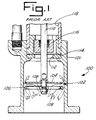
- FIG. 1 there is shown a detail elevation view of a prior art chop-check valve 100 having a cylinder or housing 101 containing a primer valve 102 comprised of two valve plates 104 and 106.
- the valve plate 106 which has flow openings 108 therethrough is secured to the end of the drive rod 110.
- the valve plate 104 is axially slidable on the drive rod 110 between a first position against the valve plate 106, precluding flow through the flow openings 108, and a second position spaced from the valve plate 106, as shown in FIG. 1 to permit flow of viscous material through the flow openings 108.
- the viscous material will pass through the opening 112 in valve seat 114 and about the floating check valve 116 into chamber 118, from which it can be pumped to a desired place, for example, a storage tank.
- the chop-check pump 10 comprises basically a cylinder means 12 containing therein piston means 14, which are actuated by drive rod means 16 operatively connected to motor means 18 for moving same axially within the cylinder means 12.
- the motor means 18 may be an air motor having a flange 20 at the lower end. Spacer rods 22 connect the flange 20 of the air motor 18 to the cylinder means 12.
- the air motor 18 is connected to a suitable source of air, e.g. 1,034 MPa (150 p.s.i.), and is adapted to reciprocate the drive rod means 16 to which it is connected at the upper end.
- the drive rod means 16 comprises an upper rod 26 secured at its upper end to the air motor 18 and a lower rod 30.
- the upper rod 26 has an enlarged intermediate rod section 28.
- the lower rod 30 is connected at its upper end in a suitable manner to intermediate rod section 28.
- Piston means 14 comprises an annular piston 36 carried about the intermediate rod 28 of the drive rod means 16.
- Packing 38 is provided between piston 36 and the inner wall of the cylinder means 12 to help seal between the exterior of piston 36 and the inner wall of the cylinder means 12.
- a flow passage 40 is provided between the internal wall of the piston 36 and the exterior of the intermediate rod 28.
- Valve surface 42 is formed on the intermediate rod section 28. The valve surface 42 is adapted to cooperate with a valve seat 44 on the piston 36. When the valve surface 42 engages the valve seat 44 as shown in FIG. 2, flow of material from the chamber 48 to the flow passage 40 is precluded. When the valve surface 42 is away from the valve seat 44 on the piston 36, as shown in FIG. 3, material can pass from chamber 48 to flow passage 40.
- piston 36 is confined for movement between a shoulder 49 on the lower end of the upper rod 26 and the valve surface 42.
- the piston 36 has a lesser axial extent than the distance between the shoulder 49 and the valve surface 42.
- An outlet 50 is provided in the side of the cylinder means 12. Material pumped by chop-check pump 10 will pass through outlet 50 into a suitable conduit for discharge as desired.
- a floating check valve mechanism 56 is provided in the cylinder means 12 adjacent the valve seat 58 for opening and closing the passage through the valve seat 58.
- Sleeve 60 is secured to the cylinder means 12 at the bottom of chamber 48.
- Sleeve 60 has a shoulder 62 for limiting upward movement of the body 64 of the floating check valve mechanism 56.
- the primer valve 70 of the present invention is connected to the lower rod 30.
- the primer valve 70 comprises a distal valve plate 74 affixed to the end of the lower rod 30 and a slidable valve plate 76 slidable axially on the lower rod 30 between a position engaging the distal valve plate 74 (FIG. 2) and a position spaced from the distal valve plate 74 (FIG. 3).
- the slidable valve plate 76 has an outer diameter greater than that of the distal valve plate 74.
- the configuration of the slidable valve plate 76 is complementary to that of the interior of the wall of the cylinder with which it is associated. In the embodiment shown, both the slidable valve plate 76 and the interior wall of the cylinder or housing are cylindrical.
- the slidable valve plate 76 is generally a washer-like element having slot-like openings 77 therein.
- the embodiment of FIG. 4 shows three openings 77, each having the general configuration of an elongated arcuate slot.
- the openings 77 are rounded at the ends.
- the sides are generally curved and in parallel relationship to one another.
- the distal valve plate 74 is constructed and arranged to provide a sharp edge 80 on the bottom for facilitating penetration of the primer valve into the viscous or stick material to be pumped. (See FIGS. 2, 3 and 7).
- the sharp edge 80 is formed at the apex of converging planar surfaces 82, 84 which define the bottom of the distal valve plate 74. Material will be directed both outwardly of the distal plate member 74 by surface 82 and inwardly to the passage means in the distal plate member 74 by surface 84.
- the embodiment of FIG. 6 shows three openings 75, each having the general configuration of an elongated, arcuate slot. The combined areas of the elongated, arcuate slot-like openings 75 is slightly less than one half of the combined areas of the openings 77. Central openings in the plates 74, 76 receive the drive rod.
- the openings 75 of the distal valve plate 74 and the openings 77 of the slidable valve plate 76 are configured in design so that when the plates 74 and 76 are abutting one against the other, the openings are closed.
- the pattern of slots or openings 75 and 77 is such that a solid plate is provided as a result of the plates 74 and 76 impinging one upon the other.
- the plates 74 and 76 do engage one against the other during the upstroke or pumping stroke of the pump.
- the slidable plate 76 which has a greater diameter or extent than the fixed or distal plate 74 will separate from the distal plate 74 due to the action of the fluid against the peripheral edge of the slidable valve plate 76.
- the passages in the distal plate 74 are effectively opened for flow of viscous material therethrough.
- the passages in the slidable valve plate 76 are opened or exposed for flow of viscous material therethrough.
- the particular pattern or flow path in the plates 74 and 76 may be varied depending upon the material which is being pumped and various other needs.
- the stroke or movement of the slidable plate 76 may also be varied depending upon the fluid being pumped and other requirements.
- the valve plate 74 may be adjustably secured in axial relationship along the drive rod 30 by suitable means, e.g. a threaded bolt and shims or a threaded connection between the distal valve plate and the drive rod and a lock nut for retaining plate 74 in adjusted position.
- suitable means e.g. a threaded bolt and shims or a threaded connection between the distal valve plate and the drive rod and a lock nut for retaining plate 74 in adjusted position.
- the distance between the top surface of the valve plate 74 and the shoulder 86 on the drive rod 30 can be adjusted. In this matter the stroke or amount of axial movement of the slidable valve plate 76 can be adjusted.
- FIGS. 8 to 15 there are shown alternative valve plates having additional configurations of the slots or openings in the plates.
- the plates 174 and 176 (FIGS. 8 and 9) have pluralities of straight elongated slots 175, 177 respectively.
- the respective slots 175, 177 are generally perpendicular to a radius in respective quadrants.
- plates 174 and 176 are keyed to the rod 30 so that when slidable valve plate 176 slides on the rod 30 it will maintain its orientation.
- a pattern of slots associated with each of the plates 174 and 176 is such that the slots are arranged at generally equal radial distances from the rod 30. This is possible since the plates 174 and 176 cannot rotate relative to one another.
- the slots or openings 175 and 177 in the two plates 174 and 176 are radially offset, or non-aligned, as viewed in plan.
- the valve plates 174 and 176 will abut so as to preclude flow of material through the slots or openings in the valve plates.
- the valve plates 174 and 176 will separate and flow will be permitted through the slots or openings 175, 177.
- FIGS. 10 and 11 illustrate plates 274 and 276 having elongated arcuate slots 275 and 277 respectively. Because of the curved nature and arrangement of the slots 275 and 277, it is not necessary to maintain a specific radial orientation of one plate with respect to the other.
- the area of the flow through passages or openings in plates 74, 76, 174, 176, 274, 276 relative to the areas of the plates will generally be slightly less than one-half the area of the respective plates.
- FIGS. 12 and 13 show a further embodiment of valve plates wherein the plates are keyed to the drive shaft to maintain the openings in each plate in a predetermined radial orientation.
- Fixed valve plate 374 and slidable valve plate 376 have substantially identical openings 375 and 377 therein. The openings are in opposed quadrants and occupy essentially a quadrant. The openings in one plate are the reverse of the openings in the other plate.
- the plates 374 and 376 may be keyed to a drive rod through keyed slots 378 and 379 respectively.
- FIGS. 14 and 15 show a further embodiment of valve plates similar to the embodiment of FIGS. 12 and 13, wherein the opening in one plate is the reverse of that in the other plate.
- the opening 475 in plate 474 occupies almost one-half of the area of the plate 474.
- opening 477 occupies almost one-half of the area of plate 476.
- the plates 474 and 476 may be keyed to a drive rod through keyed slots 478 and 479 to maintain the radial orientation of the openings 475 and 477.
- the fixed valve plate may be larger or smaller in outside diameter than the slidable valve plate or the plates could have substantially the same outer diameter as shown in the embodiments of FIGS. 8 and 9, FIGS. 10 and 11, FIGS. 12 and 13 and FIGS. 14 and 15.
- bottoms of the distal valve plates are not shown in the embodiments of FIGS. 8, 10, 12 and 14, it is preferred that the bottoms be constructed and arranged with a circular sharp edge similar to that shown in FIG. 7.
- the areas of the flow passages or openings in plates 374, 376 and 474, 476 will generally be slightly less than one-half the areas of the respective plates.
- the improved primer valve of the present invention increases penetration into viscous materials and provides for improved flow through the primer valve. Contributing to the improved performance in one important aspect is the uniquely configured distal valve plate bottom. Another aspect of the improved primer valve for a chop-check valve is the enhanced flow path provided by the flow passages in both the distal valve plate and the slidable valve plate. Yet another aspect of improvement is the construction of the slidable valve plate such that the area of the flow passages therethrough are slightly less than one-half the cross-sectional area of the slidable valve plate.
Landscapes
- Engineering & Computer Science (AREA)
- Mechanical Engineering (AREA)
- General Engineering & Computer Science (AREA)
- Details Of Reciprocating Pumps (AREA)
- Reciprocating Pumps (AREA)
- Check Valves (AREA)
- Structures Of Non-Positive Displacement Pumps (AREA)
- Compressor (AREA)
Abstract
Description
- The present invention pertains to a chop-check pump, and more particularly to an improved chop-check pump for the pumping of heavy viscous material, with or without fibrous content.
- Prior art pumps for viscous material which include a single plate fixed to a drive rod are known. Examples are the Lincoln Pile Drive Pump Model 83612, the Gray Company, Presidents Pumps Models 205-831 and 206-620; and the Pyles Industries, Inc. double-acting chopping check pump.
- An improvement in such pumps with single plates was provided by pumps having two cooperating valve plates, with holes or passages in one of the valve plates. Examples of known pumps having two valve plates are the Series 4 pumps of Johnstone Pump Company, Inc. and the Model 650491 and 650492 pumps of The Aro Corporation, assignee of the present invention.
- Another pump having a fixed plate and a slidable plate, the fixed plate having passages therethrough, is described in EP-A-0238380.
- Viewed from one aspect, the present invention provides a chop-check pump for viscous material, said pump of the type having cylinder means defining an axis, a drive rod which is axially movable within the cylinder means, a primer valve attached to one end of the drive rod and movable with the drive rod, and a floating check valve mechanism associated with the cylinder means at an outlet from the cylinder means at the end through which the drive rod extends into the cylinder means, said primer valve comprising a distal valve plate at the end of the rod and fixed to the rod, said distal valve plate having flow passage means therein, and a slidable valve plate on the drive rod slidable between a position against the distal valve plate and a position spaced from the distal valve plate,
characterised by said slidable valve plate having a configuration complementary to that of the cross section of the cylinder means, and the slidable valve plate having flow passage means which is exposed only when the plates are separated upon movement of the drive rod in a first direction into the cylinder and engagement of the valve plates with a viscous material within the cylinder means, said flow passage means being closed to flow upon the slidable valve plate engaging against the distal plate when the drive rod is moved in the reverse direction to thereby pump fluid from the cylinder means in response to movement of the slidable valve plate and distal valve plate. - An object of this invention is to provide an improved chop-check pump for viscous material that provides improved penetration in heavy or thick materials.
- Another object of the present invention is to provide a chop-check pump with an improved primer valve for enhancing flow characteristics by increasing the flow area and by providing a more direct path for material flow.
- Yet another object of the present invention is to provide a chop-check pump having an improved primer valve comprised of a pair of cooperating plate members, with each of the plate members having flow passages therein.
- Still another object of the present invention is to provide a chop-check pump for viscous material with an improved primer valve comprised of a pair of plate members, each with passages therethrough for the viscous material with one of the plate members fixed on an end of a drive rod and the other plate member axially slidable on the drive rod, the plate members cooperating to preclude flow of viscous material between the plate members in one direction of drive rod movement, and to permit flow of viscous material between the plate members in the opposite direction of drive rod movement, the fixed plate member constructed and arranged with an edge on the bottom configured to facilitate penetration of the primer valve into viscous material.
- Yet another object of the present invention is to provide an improved primer valve for a chop-check pump comprised of a pair of plate members, one fixed on a drive rod and the other slidable on the drive rod toward and away from the fixed plate member, the plate members each having flow passages therethrough, the cross-sectional area of the flow passage in the slidable valve being slightly less than one-half the cross-sectional area of the slidable valve plate.
- Other objects and advantages of the present invention will be made more apparent hereinafter.
- There is shown on the attached drawing a presently preferred embodiment of the present invention wherein like numerals refer to like elements in the various views and wherein;
- FIG. 1 is a detail side elevation view, partially in section, illustrating a prior art chop-check pump having a primer valve with two plates, only one of which has passages therethrough;
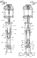
- FIG. 2 is a side elevation view partially in section of a chop-check pump embodying the present invention, and illustrating the primer valve closed during upstroke operations;
- FIG. 3 is a side elevation view similar to FIG. 2, and illustrating the primer valve open during downstroke operation of the chop-check pump;
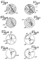
- FIG. 4 is a plan view of the slidable valve plate of the chop-check pump of FIGS. 2 and 3;
- FIG. 5 is a cross-sectional view of the slidable valve plate taken along line 5-5 of FIG. 4;
- FIG. 6 is a plan view of the distal valve plate of the chop-check valve of FIGS. 2 and 3;
- FIG. 7 is a cross-sectional view of the distal valve plate taken along line 7-7 of FIG. 6;
- FIG. 8 is a plan view of a modified distal valve plate;
- FIG. 9 is a plan view of a modified slidable valve plate that is associated with the distal valve plate of FIG. 8;
- FIG. 10 is a plan view of a further modified distal valve plate;
- FIG. 11 is a plan view of a modified slidable valve plate that is associated with the distal valve plate of FIG. 10;
- FIG. 12 is a plan view of another modified distal valve plate;
- FIG. 13 is a plan view of a modified slidable valve plate that is associated with the distal valve plate of FIG. 12;
- FIG. 14 is a plan view of yet another modified distal valve plate member; and
- FIG. 15 is a plan view of a slidable valve plate that is associated with the distal valve plate of FIG. 14.
- In FIG. 1 there is shown a detail elevation view of a prior art chop-
check valve 100 having a cylinder orhousing 101 containing aprimer valve 102 comprised of twovalve plates valve plate 106, which hasflow openings 108 therethrough is secured to the end of thedrive rod 110. Thevalve plate 104 is axially slidable on thedrive rod 110 between a first position against thevalve plate 106, precluding flow through theflow openings 108, and a second position spaced from thevalve plate 106, as shown in FIG. 1 to permit flow of viscous material through theflow openings 108. The viscous material will pass through theopening 112 invalve seat 114 and about the floatingcheck valve 116 intochamber 118, from which it can be pumped to a desired place, for example, a storage tank. - Referring to FIGS. 2 and 3, there is shown the chop-check pump of the present invention. The chop-
check pump 10 comprises basically a cylinder means 12 containing therein piston means 14, which are actuated by drive rod means 16 operatively connected to motor means 18 for moving same axially within the cylinder means 12. - The motor means 18 may be an air motor having a
flange 20 at the lower end.Spacer rods 22 connect theflange 20 of theair motor 18 to the cylinder means 12. Theair motor 18 is connected to a suitable source of air, e.g. 1,034 MPa (150 p.s.i.), and is adapted to reciprocate the drive rod means 16 to which it is connected at the upper end. - The drive rod means 16 comprises an
upper rod 26 secured at its upper end to theair motor 18 and alower rod 30. Theupper rod 26 has an enlargedintermediate rod section 28. Thelower rod 30 is connected at its upper end in a suitable manner tointermediate rod section 28. - Piston means 14 comprises an
annular piston 36 carried about theintermediate rod 28 of the drive rod means 16.Packing 38 is provided betweenpiston 36 and the inner wall of the cylinder means 12 to help seal between the exterior ofpiston 36 and the inner wall of the cylinder means 12. Aflow passage 40 is provided between the internal wall of thepiston 36 and the exterior of theintermediate rod 28.Valve surface 42 is formed on theintermediate rod section 28. Thevalve surface 42 is adapted to cooperate with avalve seat 44 on thepiston 36. When thevalve surface 42 engages thevalve seat 44 as shown in FIG. 2, flow of material from thechamber 48 to theflow passage 40 is precluded. When thevalve surface 42 is away from thevalve seat 44 on thepiston 36, as shown in FIG. 3, material can pass fromchamber 48 to flowpassage 40. - It will be understood that
piston 36 is confined for movement between ashoulder 49 on the lower end of theupper rod 26 and thevalve surface 42. Thepiston 36 has a lesser axial extent than the distance between theshoulder 49 and thevalve surface 42. - An
outlet 50 is provided in the side of the cylinder means 12. Material pumped by chop-check pump 10 will pass throughoutlet 50 into a suitable conduit for discharge as desired. - A floating
check valve mechanism 56 is provided in the cylinder means 12 adjacent thevalve seat 58 for opening and closing the passage through thevalve seat 58.Sleeve 60 is secured to the cylinder means 12 at the bottom ofchamber 48.Sleeve 60 has ashoulder 62 for limiting upward movement of thebody 64 of the floatingcheck valve mechanism 56. - The
primer valve 70 of the present invention is connected to thelower rod 30. Theprimer valve 70 comprises adistal valve plate 74 affixed to the end of thelower rod 30 and aslidable valve plate 76 slidable axially on thelower rod 30 between a position engaging the distal valve plate 74 (FIG. 2) and a position spaced from the distal valve plate 74 (FIG. 3). - The
slidable valve plate 76 has an outer diameter greater than that of thedistal valve plate 74. The configuration of theslidable valve plate 76 is complementary to that of the interior of the wall of the cylinder with which it is associated. In the embodiment shown, both theslidable valve plate 76 and the interior wall of the cylinder or housing are cylindrical. - There are flow openings in both the
distal valve member 74 and theslidable valve member 76 for maximizing the flow area for the flow of viscous material intochamber 48, as will be described more fully with reference to FIGS. 4-7. - As best seen in FIGS. 4 and 5, the
slidable valve plate 76 is generally a washer-like element having slot-like openings 77 therein. The embodiment of FIG. 4 shows threeopenings 77, each having the general configuration of an elongated arcuate slot. Theopenings 77 are rounded at the ends. The sides are generally curved and in parallel relationship to one another. - The
distal valve plate 74 is constructed and arranged to provide asharp edge 80 on the bottom for facilitating penetration of the primer valve into the viscous or stick material to be pumped. (See FIGS. 2, 3 and 7). Thesharp edge 80 is formed at the apex of convergingplanar surfaces distal valve plate 74. Material will be directed both outwardly of thedistal plate member 74 bysurface 82 and inwardly to the passage means in thedistal plate member 74 bysurface 84. The embodiment of FIG. 6 shows threeopenings 75, each having the general configuration of an elongated, arcuate slot. The combined areas of the elongated, arcuate slot-like openings 75 is slightly less than one half of the combined areas of theopenings 77. Central openings in theplates - The
openings 75 of thedistal valve plate 74 and theopenings 77 of theslidable valve plate 76, are configured in design so that when theplates openings plates plates slidable plate 76 which has a greater diameter or extent than the fixed ordistal plate 74 will separate from thedistal plate 74 due to the action of the fluid against the peripheral edge of theslidable valve plate 76. When separated a limited distance determined by the extent of a stop orshoulder 86 on therod 30, the passages in thedistal plate 74 are effectively opened for flow of viscous material therethrough. Similarly, the passages in theslidable valve plate 76 are opened or exposed for flow of viscous material therethrough. Thus, when theplates plates - The particular pattern or flow path in the
plates slidable plate 76 may also be varied depending upon the fluid being pumped and other requirements. - The
valve plate 74 may be adjustably secured in axial relationship along thedrive rod 30 by suitable means, e.g. a threaded bolt and shims or a threaded connection between the distal valve plate and the drive rod and a lock nut for retainingplate 74 in adjusted position. The distance between the top surface of thevalve plate 74 and theshoulder 86 on thedrive rod 30 can be adjusted. In this matter the stroke or amount of axial movement of theslidable valve plate 76 can be adjusted. - In FIGS. 8 to 15 there are shown alternative valve plates having additional configurations of the slots or openings in the plates. The
plates 174 and 176 (FIGS. 8 and 9) have pluralities of straightelongated slots respective slots plates rod 30 so that whenslidable valve plate 176 slides on therod 30 it will maintain its orientation. In such circumstance a pattern of slots associated with each of theplates rod 30. This is possible since theplates openings plates valve plates valve plates openings - FIGS. 10 and 11 illustrate
plates arcuate slots slots - Note also that the area of the flow through passages or openings in
plates - FIGS. 12 and 13 show a further embodiment of valve plates wherein the plates are keyed to the drive shaft to maintain the openings in each plate in a predetermined radial orientation.
Fixed valve plate 374 andslidable valve plate 376 have substantiallyidentical openings plates slots - FIGS. 14 and 15 show a further embodiment of valve plates similar to the embodiment of FIGS. 12 and 13, wherein the opening in one plate is the reverse of that in the other plate. The
opening 475 inplate 474 occupies almost one-half of the area of theplate 474. Similarly opening 477 occupies almost one-half of the area ofplate 476. Theplates slots openings - The fixed valve plate may be larger or smaller in outside diameter than the slidable valve plate or the plates could have substantially the same outer diameter as shown in the embodiments of FIGS. 8 and 9, FIGS. 10 and 11, FIGS. 12 and 13 and FIGS. 14 and 15.
- Though the bottoms of the distal valve plates are not shown in the embodiments of FIGS. 8, 10, 12 and 14, it is preferred that the bottoms be constructed and arranged with a circular sharp edge similar to that shown in FIG. 7.
- As with the earlier described embodiments, the areas of the flow passages or openings in
plates - The improved primer valve of the present invention increases penetration into viscous materials and provides for improved flow through the primer valve. Contributing to the improved performance in one important aspect is the uniquely configured distal valve plate bottom. Another aspect of the improved primer valve for a chop-check valve is the enhanced flow path provided by the flow passages in both the distal valve plate and the slidable valve plate. Yet another aspect of improvement is the construction of the slidable valve plate such that the area of the flow passages therethrough are slightly less than one-half the cross-sectional area of the slidable valve plate.
- While a presently preferred embodiment of the invention has been shown and described, it will be understood that various changes and modifications may be made therein without departing from the invention.
Claims (10)
- A chop-check pump for viscous material, said pump of the type having cylinder means (12) defining an axis, a drive rod (30) which is axially movable within the cylinder means (12), a primer valve attached to one end of the drive rod (30) and movable with the drive rod (30), and a floating check valve mechanism (56) associated with the cylinder means (12) at an outlet from the cylinder means (12) at the end through which the drive rod (30) extends into the cylinder means (12), said primer valve comprising a distal valve plate (74) at the end of the rod (30) and fixed to the rod (30), said distal valve plate (74) having flow passage means (75) therein, and a slidable valve plate (76) on the drive rod (30) slidable between a position against the distal valve plate (74) and a position spaced from the distal valve plate (74),
characterised by said slidable valve plate (76) having a configuration complementary to that of the cross section of the cylinder means (12), and the slidable valve plate (76) having flow passage means (77) which is exposed only when the plates (74,76) are separated upon movement of the drive rod (30) in a first direction into the cylinder (12) and engagement of the valve plates (74,76) with a viscous material within the cylinder means (12), said flow passage means (75,77) being closed to flow upon the slidable valve plate (76) engaging against the distal plate (74) when the drive rod (30) is moved in the reverse direction to thereby pump fluid from the cylinder means (12) in response to movement of the slidable valve plate (76) and distal valve plate (74). - The pump of claim 1 further characterised in that the flow passage means (75) in the distal valve plate (74) is at least slightly less in cross-sectional area than one half of the cross-section area of the flow passage means (77) in the slidable valve plate (76).
- The pump of claim 1 or 2 further characterised in that the flow passage means (77) in the slidable valve plate (76) has an area slightly less than one-half of the area of the slidable valve plate (76).
- The pump of claim 1 further characterised in that the flow passage means (175,275,375,475) in the distal valve plate (174,274,374,474) and the flow passage means (177,277,377,477) in the slidable valve plate (176,276, 376,476) each has an area slightly less than one half of the area of the respective plates.
- The pump of any preceding claim further characterised in that the bottom of the distal valve plate (74) is configured for facilitating downward movement of the primer valve into the viscous material.
- The pump of any preceding claim further characterised in that the bottom of the distal valve plate (74) is configured for facilitating movement of the primer valve into the viscous material and for directing viscous material through the passage means (75) and about the periphery of the distal plate (74).
- The pump of claim 5 or 6 further characterised in that the distal valve plate (74) has a sharp edge (80) formed on the bottom thereof for facilitating downward movement of the primer valve into the viscous material.
- The pump of any preceding claim further characterised in that the flow passage means (77) in the slidable valve plate (76) comprises at least one slot-like opening.
- The pump of any preceding claim further characterised in that the flow passage means in the distal valve plate (74) comprises at least one slot-like opening (75).
- The pump of any preceding claim further characterised by said slidable valve plate (76) having a radial extent greater than that of the distal valve plate (74).
Applications Claiming Priority (3)
| Application Number | Priority Date | Filing Date | Title |
|---|---|---|---|
| US07/404,493 US4978283A (en) | 1989-09-08 | 1989-09-08 | Primer valve for chop-check pump |
| PCT/US1990/000829 WO1991003645A1 (en) | 1989-09-08 | 1990-02-09 | Primer valve for chop-check pump |
| US404493 | 2003-04-01 |
Publications (2)
| Publication Number | Publication Date |
|---|---|
| EP0490895A1 EP0490895A1 (en) | 1992-06-24 |
| EP0490895B1 true EP0490895B1 (en) | 1995-04-19 |
Family
ID=23599831
Family Applications (1)
| Application Number | Title | Priority Date | Filing Date |
|---|---|---|---|
| EP90906444A Expired - Lifetime EP0490895B1 (en) | 1989-09-08 | 1990-02-09 | Primer valve for chop-check pump |
Country Status (8)
| Country | Link |
|---|---|
| US (1) | US4978283A (en) |
| EP (1) | EP0490895B1 (en) |
| JP (1) | JPH0819901B2 (en) |
| AT (1) | ATE121504T1 (en) |
| AU (1) | AU631422B2 (en) |
| CA (1) | CA2010403C (en) |
| DE (1) | DE69018831T2 (en) |
| WO (1) | WO1991003645A1 (en) |
Families Citing this family (6)
| Publication number | Priority date | Publication date | Assignee | Title |
|---|---|---|---|---|
| US5067882A (en) * | 1990-06-20 | 1991-11-26 | Nordson Corporation | Dual-acting, reciprocating piston pump |
| US5605446A (en) * | 1994-10-18 | 1997-02-25 | Graco Inc. | High viscosity material pump having valved priming piston |
| US6644941B1 (en) | 2002-04-18 | 2003-11-11 | Ingersoll-Rand Company | Apparatus and method for reducing ice formation in gas-driven motors |
| US6901960B2 (en) * | 2002-09-06 | 2005-06-07 | Ingersoll-Rand Company | Double diaphragm pump including spool valve air motor |
| US6865981B2 (en) * | 2003-03-11 | 2005-03-15 | Ingersoll-Rand Company | Method of producing a pump |
| US6883417B2 (en) * | 2003-03-19 | 2005-04-26 | Ingersoll-Rand Company | Connecting configuration for a diaphragm in a diaphragm pump |
Family Cites Families (8)
| Publication number | Priority date | Publication date | Assignee | Title |
|---|---|---|---|---|
| US1357624A (en) * | 1918-01-02 | 1920-11-02 | Moon Brothers Mfg Company | Pump-piston |
| US2741994A (en) * | 1951-06-26 | 1956-04-17 | Ernest G Dann | Lift pump |
| US3349715A (en) * | 1965-04-13 | 1967-10-31 | Stewart Warner Corp | Pump |
| US3335673A (en) * | 1966-01-17 | 1967-08-15 | Forrest Henry De | Manually operable pump |
| US3532446A (en) * | 1967-04-04 | 1970-10-06 | Margrete L Stinnes | Sliding seal and valve for reciprocating pump |
| US3809508A (en) * | 1971-12-06 | 1974-05-07 | Maruyama Mfg Co | Pump |
| JPS56136176U (en) * | 1980-03-14 | 1981-10-15 | ||
| ES2011806B3 (en) * | 1986-02-20 | 1990-02-16 | Saint-Gobain Vitrage | HIGH VISCOSITY MATTER PUMP. |
-
1989
- 1989-09-08 US US07/404,493 patent/US4978283A/en not_active Expired - Lifetime
-
1990
- 1990-02-09 AT AT90906444T patent/ATE121504T1/en not_active IP Right Cessation
- 1990-02-09 WO PCT/US1990/000829 patent/WO1991003645A1/en not_active Ceased
- 1990-02-09 EP EP90906444A patent/EP0490895B1/en not_active Expired - Lifetime
- 1990-02-09 AU AU54325/90A patent/AU631422B2/en not_active Ceased
- 1990-02-09 JP JP2-506085A patent/JPH0819901B2/en not_active Expired - Lifetime
- 1990-02-09 DE DE69018831T patent/DE69018831T2/en not_active Expired - Fee Related
- 1990-02-20 CA CA002010403A patent/CA2010403C/en not_active Expired - Fee Related
Also Published As
| Publication number | Publication date |
|---|---|
| CA2010403C (en) | 1995-10-03 |
| CA2010403A1 (en) | 1991-03-08 |
| US4978283A (en) | 1990-12-18 |
| DE69018831T2 (en) | 1995-08-17 |
| EP0490895A1 (en) | 1992-06-24 |
| AU631422B2 (en) | 1992-11-26 |
| JPH0819901B2 (en) | 1996-03-04 |
| AU5432590A (en) | 1991-04-08 |
| DE69018831D1 (en) | 1995-05-24 |
| WO1991003645A1 (en) | 1991-03-21 |
| JPH0819901B1 (en) | 1996-03-04 |
| ATE121504T1 (en) | 1995-05-15 |
Similar Documents
| Publication | Publication Date | Title |
|---|---|---|
| US4860995A (en) | Valve element for use in pumps for handling fluids containing abrasive materials | |
| US5564911A (en) | Pump, control valve and diaphragm | |
| US4984970A (en) | Arrangements on coned rings which are applicable in high pressure pumps and related devices | |
| AU631422B2 (en) | Primer valve for chop-check pump | |
| CN102086853A (en) | Piston machine for use as a vacuum pump for medical purposes | |
| US5836751A (en) | Reciprocating piston pump | |
| US4035107A (en) | Pump system for high pressure abrasive liquids | |
| CA2106201A1 (en) | Radial pump | |
| US4679989A (en) | Pump shovel bulk unloader | |
| US5407332A (en) | High suction intake wiper | |
| US181168A (en) | Improvement in pump-valves | |
| US39974A (en) | Improvement in pumps | |
| EP3816438B1 (en) | Automatic bidirectional valve and pump provided with said valve | |
| JPH04503549A (en) | Priming valve for tip check type pumps | |
| CH657665A5 (en) | Rotary piston engine | |
| US4767291A (en) | Single valve pump | |
| US20230407855A1 (en) | Fluid dosing system | |
| DE4325282A1 (en) | Vacuum pump with auxiliary device | |
| US116703A (en) | Improvement in pumps | |
| US49408A (en) | Improvement in pumps | |
| US619033A (en) | Combined submerged lifting and force pump | |
| US42705A (en) | Improvement in pumps for deep wells | |
| US480169A (en) | caeow | |
| US20060275165A1 (en) | Pump with reciprocating high pressure seal and valve for vehicle braking systems | |
| US171475A (en) | Improvement in pistons or plungers for force-pumps |
Legal Events
| Date | Code | Title | Description |
|---|---|---|---|
| PUAI | Public reference made under article 153(3) epc to a published international application that has entered the european phase |
Free format text: ORIGINAL CODE: 0009012 |
|
| 17P | Request for examination filed |
Effective date: 19920323 |
|
| AK | Designated contracting states |
Kind code of ref document: A1 Designated state(s): AT BE CH DE DK ES FR GB IT LI LU NL SE |
|
| 17Q | First examination report despatched |
Effective date: 19930517 |
|
| GRAA | (expected) grant |
Free format text: ORIGINAL CODE: 0009210 |
|
| AK | Designated contracting states |
Kind code of ref document: B1 Designated state(s): AT BE CH DE DK ES FR GB IT LI LU NL SE |
|
| PG25 | Lapsed in a contracting state [announced via postgrant information from national office to epo] |
Ref country code: NL Free format text: LAPSE BECAUSE OF FAILURE TO SUBMIT A TRANSLATION OF THE DESCRIPTION OR TO PAY THE FEE WITHIN THE PRESCRIBED TIME-LIMIT Effective date: 19950419 Ref country code: LI Effective date: 19950419 Ref country code: ES Free format text: THE PATENT HAS BEEN ANNULLED BY A DECISION OF A NATIONAL AUTHORITY Effective date: 19950419 Ref country code: DK Effective date: 19950419 Ref country code: CH Effective date: 19950419 Ref country code: BE Effective date: 19950419 Ref country code: AT Effective date: 19950419 |
|
| REF | Corresponds to: |
Ref document number: 121504 Country of ref document: AT Date of ref document: 19950515 Kind code of ref document: T |
|
| REF | Corresponds to: |
Ref document number: 69018831 Country of ref document: DE Date of ref document: 19950524 |
|
| ITF | It: translation for a ep patent filed | ||
| REG | Reference to a national code |
Ref country code: CH Ref legal event code: PL |
|
| ET | Fr: translation filed | ||
| NLV1 | Nl: lapsed or annulled due to failure to fulfill the requirements of art. 29p and 29m of the patents act | ||
| PG25 | Lapsed in a contracting state [announced via postgrant information from national office to epo] |
Ref country code: SE Effective date: 19960210 |
|
| PLBE | No opposition filed within time limit |
Free format text: ORIGINAL CODE: 0009261 |
|
| STAA | Information on the status of an ep patent application or granted ep patent |
Free format text: STATUS: NO OPPOSITION FILED WITHIN TIME LIMIT |
|
| PG25 | Lapsed in a contracting state [announced via postgrant information from national office to epo] |
Ref country code: LU Free format text: LAPSE BECAUSE OF NON-PAYMENT OF DUE FEES Effective date: 19960229 |
|
| 26N | No opposition filed | ||
| REG | Reference to a national code |
Ref country code: GB Ref legal event code: IF02 |
|
| PGFP | Annual fee paid to national office [announced via postgrant information from national office to epo] |
Ref country code: FR Payment date: 20020117 Year of fee payment: 13 |
|
| PGFP | Annual fee paid to national office [announced via postgrant information from national office to epo] |
Ref country code: DE Payment date: 20020118 Year of fee payment: 13 |
|
| PGFP | Annual fee paid to national office [announced via postgrant information from national office to epo] |
Ref country code: GB Payment date: 20020121 Year of fee payment: 13 |
|
| PG25 | Lapsed in a contracting state [announced via postgrant information from national office to epo] |
Ref country code: GB Free format text: LAPSE BECAUSE OF NON-PAYMENT OF DUE FEES Effective date: 20030209 |
|
| PG25 | Lapsed in a contracting state [announced via postgrant information from national office to epo] |
Ref country code: DE Free format text: LAPSE BECAUSE OF NON-PAYMENT OF DUE FEES Effective date: 20030902 |
|
| GBPC | Gb: european patent ceased through non-payment of renewal fee | ||
| PG25 | Lapsed in a contracting state [announced via postgrant information from national office to epo] |
Ref country code: FR Free format text: LAPSE BECAUSE OF NON-PAYMENT OF DUE FEES Effective date: 20031031 |
|
| REG | Reference to a national code |
Ref country code: FR Ref legal event code: ST |
|
| PG25 | Lapsed in a contracting state [announced via postgrant information from national office to epo] |
Ref country code: IT Free format text: LAPSE BECAUSE OF NON-PAYMENT OF DUE FEES;WARNING: LAPSES OF ITALIAN PATENTS WITH EFFECTIVE DATE BEFORE 2007 MAY HAVE OCCURRED AT ANY TIME BEFORE 2007. THE CORRECT EFFECTIVE DATE MAY BE DIFFERENT FROM THE ONE RECORDED. Effective date: 20050209 |