EP0489975B1 - Reinigungsvorrichtung für ein Filterelement - Google Patents
Reinigungsvorrichtung für ein Filterelement Download PDFInfo
- Publication number
- EP0489975B1 EP0489975B1 EP19900203249 EP90203249A EP0489975B1 EP 0489975 B1 EP0489975 B1 EP 0489975B1 EP 19900203249 EP19900203249 EP 19900203249 EP 90203249 A EP90203249 A EP 90203249A EP 0489975 B1 EP0489975 B1 EP 0489975B1
- Authority
- EP
- European Patent Office
- Prior art keywords
- filter element
- air
- brush
- foreign matter
- perforations
- Prior art date
- Legal status (The legal status is an assumption and is not a legal conclusion. Google has not performed a legal analysis and makes no representation as to the accuracy of the status listed.)
- Expired - Lifetime
Links
Images

Classifications
-
- B—PERFORMING OPERATIONS; TRANSPORTING
- B01—PHYSICAL OR CHEMICAL PROCESSES OR APPARATUS IN GENERAL
- B01D—SEPARATION
- B01D46/00—Filters or filtering processes specially modified for separating dispersed particles from gases or vapours
- B01D46/24—Particle separators, e.g. dust precipitators, using rigid hollow filter bodies
- B01D46/26—Particle separators, e.g. dust precipitators, using rigid hollow filter bodies rotatable
-
- F—MECHANICAL ENGINEERING; LIGHTING; HEATING; WEAPONS; BLASTING
- F01—MACHINES OR ENGINES IN GENERAL; ENGINE PLANTS IN GENERAL; STEAM ENGINES
- F01P—COOLING OF MACHINES OR ENGINES IN GENERAL; COOLING OF INTERNAL-COMBUSTION ENGINES
- F01P11/00—Component parts, details, or accessories not provided for in, or of interest apart from, groups F01P1/00 - F01P9/00
- F01P11/12—Filtering, cooling, or silencing cooling-air
Definitions
- This invention relates to an air filtering arrangement which can generally be applied to many different devices which have to operate in an atmosphere which besides dry foreign matter, such as dust, chaff, short straw particles, etc., also contains damp and gluey particles and in which air from this athmosphere has to pass through relatively small openings in an element of the filtering arrangement to hold back this foreign matter on the one hand, but whereby there is a danger of the openings becoming blocked if no special precautions are taken on the other hand.
- Such an air filtering arrangement can, for example, be used with cooling devices for combustion engines or hydraulic equipment.
- One particular application of the present invention is that of harvesting machines, such as combine harvesters, since these machines, when harvesting e.g. wheat or barley, normally work in a very dusty atmosphere as they can only harvest efficiently when the whole crop is ripe and dry, whereby, during operation, a considerable amount of dust, chaff and short straw particles are displaced in the vicinity of the machine.
- Harvesting other crops however, especially corn requires only the ears of corn to be ripe and dry, while the cornstalks still may stand green and succulent as they usually are not processed through the harvesting machine but instead are comminuted thereby and left in the field. In chopping the cornstalks, sap thereof is beaten out generating clouds of damp, sticky particles.
- the ears of corn are infested e.g. by fungous diseases, resulting in a gluey powder to be spread into the air when stripping said ears from the cornstalks.
- a duct is provided exteriorly thereof which is open in the region of the blanking off plate.
- the fan operable to draw air through the filter element, generates a flow of pressurized air in said duct by virtue of the latter having its inlet opening at the pressure side of the fan. Any foreign matter falling free from the filter element in the predetermined region is captured by the pressurized air flow and is discharged at a remote location from the filter element.
- Another air filter disclosed in DE-B-453.597 which forms the basis for the preamble of claim 1, is similar to that of EP-A-0.269.765 to the extent that blanking off plates are employed for removing foreign matter from the filter element.
- brush elements in addition are operable to wipe off the outer surface of the filter screen, without intending or succeeding to clean the perforations provided therein.
- foreign particles nevertheless released from the perforations by the action of the brush elements, are carried along with the cooling air into the inside of the cooling arrangement and are likely to collect e.g. on the radiator which ultimately will perform inefficiently as a result thereof.
- an air filtering arrangement comprising :
- the fan is positioned at the downstream side of the filter element and therefore is operable to draw in air through the perforations provided therein.
- Blanking off means may be provided closely adjacent this side of the filter element for blanking off the perforations thereof over a predetermined region so as to obstruct the passage therethrough of air to be filtered whereby foreign matter collected on the opposite surface of the perforate filter falls free therefrom.
- duct means may be provided in the vicinity of the filter element at this opposite side thereof and which are open in the region of said blanking off means for exposing the filter element to a cleaning air blast captured at the pressure side of the fan.
- the brush means preferably are arranged immediately in front of the blanking off means when seen in the direction of movement of the filter element; said brush means being urged against the facing surface of the perforate filter in order to force the bristles of the brush means through the perforations for expelling any foreign matter collected therein.
- the combine harvester on which the air filtering arrangement of the present invention is applied is of generally known form and comprises a main chassis or frame 1 supported on a front pair of drive wheels 2 and a rear pair of steerable wheels 3. Supported on the main chassis 2 are an operator's platform 4, a grain tank 5, a threshing and separating mechanism indicated generally at 6, a grain cleaning mechanism indicated generally at 7, and an engine (not shown).
- a corn header 8 and elevator housing 9 extend forwardly of the main chassis 1 and the header is pivotably secured to the chassis for generally vertical movement which is controlled by extensible hydraulic cylinders 11.
- the corn header 8 separates the ears of corn from the corn stalks and the former are conveyed to the elevator housing 9 which supplies them to the threshing and separating mechanism 6 for further processing.
- the corn stalks, stripped from their ears, are comminuted by a cutter device 12 provided underneath the corn header 8 and are left on the field.
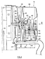
- the combine harvester further comprises a rotary air filter or screen indicated generally at 14 and illustrated in greater detail in Figures 2 and 3 of the drawings.
- the rotary air filter 14 forms part of a cooling system for the internal combustion engine of the combine harvester of which only the engine block 16 is illustrated schematically in Figure 2.
- the cooling system comprises a radiator 17 which is disposed with the engine block 16 at one side thereof and with a cooling fan 18 at the opposite side thereof.
- the cooling fan 18 is mounted on one end of a collar 19 with the other end of the collar 19 being provided with a pulley 22 which is driven by a belt 23 from a further pulley 24 in order to impart rotational drive to the cooling fan 18.
- the collar 19 is mounted for rotation, via bearings 21, on a stationary shaft 25 which itself is supported via a support frame 26 provided in a radiator housing 27.
- the rotary air screen of filter 14 is mounted for rotation on said shaft 25 via bearings 20 and 28 and comprises a filter element 29 in the form of a cylinder which is open at one end facing the radiator 17 and which is closed at the opposite end.
- the fan 18 is mounted within the cylindrical filter element 29 adjacent its open end.
- the filter element 29 is imperforate at its closed end but perforate around its periphery for at least a portion of its axial length.
- Spokes 30, connected to flanges 32 of a hub 34, are operable to rotatably support the filter element 29 on the stationary shaft 25. Rotational drive of the filter element 29 is obtained by a belt 36 engaging the cylindrical surface thereof, thereby rotating the filter 29 at a rotational speed in the range of 200 RPM for example.
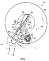
- a stationary blanking off plate 38 is provided within the filter element 29 on the aforementioned shaft 25 in a manner so as to be closely adjacent a region of the perforate periphery of the filter element 29. It will be seen from Figure 3 that, in a preferred embodiment, this plate 38 extends over an arc of approximatley 30°, thus preventing cooling air from flowing through the filter element 29 over that arc at the perforate periphery thereof. Accordingly, any dust, short particles of leaves or other foreign matter collected on the outer surface of the air filter 29 at that blanked off portion in use of the air filtering arrangement tend to fall loose of the filter element due to gravity forces and eventually also centrifugal forces whereafter this foreign matter can readily be removed.
- a pneumatic foreign matter evacuation system or "blow-off" system comprises duct means 40 which is curved so that the open end 42 thereof is directed towards, and positioned adjacent, the pressure side of the cooling fan 18, whereby the latter provides a source of pressurized air which flows through the duct 40.
- a portion 44 of the duct means 40 extends closely beneath the filter element 29 and is open at its top in the region of the blanking off plate 38.
- foreign matter that has accumulated on the perforate surface of the filter element 29 and that tends to fall loose beneath the blanking off plate 38 in a manner as already described, is picked up by the localized pressurized air flow and is discharged thereby at a remote location from the rotary air screen.
- a clogged air filter is highly ineffective and undesirable in that it can cause overheating of the combine harvester engine.
- Precautions thereagainst such as the already described blanking off plate 38 or the blow-off system 40, have proven to provide minimal effect when the obstruction of the air filter 29 is concentrated inside the perforations and not on the outer surface of the filter.
- the advantageous effect of the blanking off plate 38 is mainly based on the gravity forces succeeding to loosen foreign matter collected on the outer surface of the air filter 29.
- gravity forces alone are not sufficiently strong to extract the sticky particles from the perforations.
- the blow-off system 40 is unable to clear the filter element 29, as the flow of pressurized air generated in the duct 40 is oriented parallel to the outer surface of the filter 29, thus having no effect whatsoever on the hidden obstructions inside the perforations.
- a filter element cleaning means 46 comprising a brush 48, rotatably mounted parallel to the perforate portion of the filter element 29 and at the inner side thereof, when seen in the direction of normal air flow therethrough.
- a pair of lever arms 50 hingeably connected at 52 to the retaining members 54 of the blanking off plate 38, is operable to support the brush 48 either in an inoperative position as shown in full lines in Figure 3 or in an operative position shown in dashed lines in the same Figure.
- a solenoid 56 is attached to a mounting member 58, in turn fixedly secured to the stationary shaft 25.
- the plunger side of the solenoid 56 is provided with a threaded rod 60 which adjustably receives a bifurcated connector 62, the open end of which hingeably holds a hook-shaped member 64.
- a further threaded rod 66 is adjustably connected at one side to the hook-shaped member 64, while the other side is attached, via a ball-and-socket joint 68, to a cross member 70 which links the arms 50 to each other.
- two upright brackets 72 are welded thereto, holding inbetween a rod 74 which extends parallel to the brush 48.
- a tension spring 76 is provided between an anchor point on the mounting member 58 and the rod 74, at a portion halfway thereof.
- the spring 76 When the solenoid 56 is not energized, the spring 76 is able to swivel the brush 48 on its supporting arms 50 around their pivots 52 to its inoperative position clear from the perforate portion of the filter element 29. Any further movement away from the filter 29 is prevented by an angled member 78, firmly connected to the rod 60 of the solenoid 56 and which abuts against an extending flange 80 of the mounting member 58.
- the threated rod 60 is retracted to some degree into the solenoid body in a straight line.
- the bifurcated connector 62 is subjected to this linear movement, resulting in all intermediate members 64, 66 and 68 to swivel the levers 50 in a clockwise direction as seen in Figure 3, whereby the brush 48 is urged into its operative position against the filter element 29.
- the hook-shaped member 64 and the threaded rod 66 are not moved in a linear path since the levers 50 are pivoted around their fulcrum 52.
- the member 64 is hingeably attached at the bifurcated connector 62 by a hinge 82 which extends parallel to the hinge axis 52 of the levers 50.
- an elongated recess is provided in the extending flange 80 of the mounting members 58.
- the hook-shaped member 64 can only enter the recess with its smallest side up front, as seen in Figure 2, and thus consequently the bifurcated connector 62 must be positioned correctly to be able to make the connection.
- the bristles of the brush 48 are of a size able to pierce through the perforations in de filter element 29 without running the risk of getting stuck therein. In piercing through, the foreign particles accumulated in the perforations are repelled in the direction opposite to the direction in which they entered. As the blanking off plate 38 is positioned immediately behind the brush 48 when seen in the direction of rotation of the screen 29, the repelled particles are not given a chance to be sucked in again by the fan 18, but instead are received in the blow-off duct 44 and evacuated from the vicinity of the screen 29 and, provided the brush 48 is constructed according to some specific requirements, only a few revolutions of the screen 29 are imperative to clean the same.
- the brush 48 What the construction of the brush 48 is concerned, lightweight synthetic materials are applied to keep the weight as low as possible for reasons to avoid slip of the screen 29 on the brush 48 which would lead to excessive wear of the brush bristles.
- low friction bearings aligned with respect to each other are used to freely rotatably support the brush 48 on the lever arms 50.
- the bristles of the brush 48 should meet two almost contradicting requirements : on the one hand being wear-resistant and strong, but on the other hand being very flexible.
- the bristles are formed by nylon fibres which are attached to a hollow plastic core. To improve the cleaning efficiency, the amount of bristles must be chosen in relation to the amount of perforations instantaneously presented to the brush 48.
- the brush 48 will act as a near rigid structure and the bristles, which have to enter the perforations, will experience great difficulty to do so. In the opposite case however, if too few bristles are provided, the brush 48 will be too flexible and all the bristles will bend, without entering the perforations.
- the brush 48 need not to be in constant engagement with the filter element 29 for satisfactorily cleaning the same. Therefore, in order to prolong the lifetime of the brush 48 and to reduce power consumption of the rotary air filter drive, provisions are made for only periodically energizing the solenoid 56 and thus subjecting the filter 29 to an intermittent cleaning action.
- the solenoid 56 is connected to a low voltage electric source (not shown) by means of wires 84, which are suitably guided through a central bore in the shaft 25 for not impeding the operation of rotating elements thereon.
- Control means are included in the electric circuit comprising the electric source and the solenoid 56; the control means being operable to intermittently energize and deenergize the solenoid 56 for moving the brush 48 respectively in and out of engagement with the filter element 29.
- control means may take the form of an electric switch, mounted within reach of the operator on the platform 4.
- the control means may take the form of an electric switch, mounted within reach of the operator on the platform 4.
- control means are automatically actuated at regular intervals, without any determined action from the part of the operator being required.
- Said control means comprises an electric switch (not shown), provided underneath the operator's platform 4, which is operatively coupled to the engagement lever (equally not shown) of the graintank unloading tube.
- a timer mechanism (not shown) is also integrated in the electric circuit of the solenoid 56.
- the graintank 5 is gradually filling while the combine harvester is driven over the field.
- the operator manipulates the lever to engage the unloading tube drive.
- the electric switch underneath the platform 4 is actuated, whereby electric current is provided to the solenoid 56 and consequently the brush 48 is brought into engagement with the filter 29 for starting its cleaning operation.
- the timer mechanism ensures that, following the energizing of the solenoid 56, the current supply to this solenoid 56 is interrupted after a predetermined period of time and irrespective of the position of the lever for engaging the unloading tube drive.
- the graintank regularly has to be emptied (i.e. in the order of each half hour for example), not enough time is provided to the flow of polluted cooling air to clog the filter screen 29 beyond an acceptable level between two successive cleaning operations. As such, an optimal effect of the cooling system is guaranteed.
- the timer mechanism referred to hereabove preferably takes the form of an electronic circuit of which the operating time can be adjusted according to the needs.
- the timer mechanism may cut the current to the solenoid 56, thereby disengaging the brush 48 from the screen 29, already after a few seconds, since, as mentioned before, only a few revolutions of the screen 29 with the brush 48 in engagement are needed to remove the foreign particles from the perforations therein. All this implies that, during a full harvesting day, the brush 48 becomes operational for a reduced period of time only which nevertheless is sufficient to safeguard the free flow of cooling air through the perforated screen 29. By the same token, the lifetime of the brush 48 is increased considerably.
- control means for initiating the operation of the brush 48 operatively may be coupled to another control mechanism besides the graintank unloading device, provided said control mechanism is actuated at regular intervals during the harvesting operation.
- control mechanism is found in the header height adjustment lever (not shown) as indeed said lever is manipulated frequently for raising the header when the combine harvester starts driving on the headlands.
- One such step consists of ensuring that the inner surface of the perforate screen 29 against which the brush 48 is rubbing, is made as smooth as possible. This is accomplished by taking account of the punch direction during manufacture of the perforations in the screen 29. More specifically, the screen 29 should be assembled such that said punch direction is oriented from the inside of the screen 29 to the outside thereof, so that any serrated bulges, resulting from the punch operation, are located at the outer surface of the screen 29.
- the blow-off duct 40 may be omitted without seriously decreasing the cleaning efficiency of the brush 48.
- evacuation of the expelled particles from the filter 29 solely depends on gravity forces experienced underneath the blanking off plate 38. Also the latter may be left out from the filter arrangement, although this would demand much longer engagement periods of the brush 48 to keep the filter 29 clean, as particles expelled from the perforations are more likely to be sucked in again immediately behind the brush 48, as seen in the direction of rotation of the filter 29.
- the spokes 30, which support the filter 29, advantageously may be substituted by a set of turbine blades; these blades being acted upon by the flow of cooling air drawn through the filter by the cooling fan 18, thus rotating the filter at a relatively low rotational speed.
Landscapes
- Engineering & Computer Science (AREA)
- Chemical & Material Sciences (AREA)
- Chemical Kinetics & Catalysis (AREA)
- Combustion & Propulsion (AREA)
- Mechanical Engineering (AREA)
- General Engineering & Computer Science (AREA)
- Filtering Of Dispersed Particles In Gases (AREA)
Claims (11)
- Luftfilterungsanordnung mit:- einem perforierten Filterelement (29),- einem Gebläse (18), das betreibbar ist, um Luft, die mit Fremdstoffen verunreinigt ist, in einer vorgegebenen Richtung durch das Filterelement (29) von dessen strömungsaufwärts gelegenen Seite zu dessen strömungsabwärts gelegenen Seite zu drücken, wobei das Filterelement (29) betreibbar ist, um die Fremdstoffe festzuhalten, während die Luft durch die Perforationen des Filterelementes hindurchströmt,- einer Filterelement-Reinigungseinrichtung (46), die eine drehbare Bürsteneinrichtung (48) aufweist, die in Reinigungseingriff mit einem Abschnitt des Filterelementes (29) steht, um um von diesem festgehaltene Fremdstoffe abzulösen, und- Antriebseinrichtungen (36/.), die dazu dienen, um im Betrieb die Relativstellung des Filterelementes (29) bezüglich der Bürsteneinrichtung (48) derart zu ändern, daß andere Abschnitte des Filterelementes aufeinanderfolgend den Bürsteneinrichtungen (48) ausgesetzt sind,dadurch gekennzeichnet, daß die Bürsteneinrichtungen (48) auf der strömungsabwärts gelegenen Seite des Filterelementes (29) angeordnet sind und derart betreibbar sind, daß sie durch die Perforationen des Filterelementes in einer Richtung hindurchstechen, die der vorgegebenen Richtung entgegengesetzt ist, so daß Fremdstoffe, die sich in den Perforationen angesammelt haben, in Richtung auf die strömungsaufwärts gelegene Seite des Filterelementes (29) ausgestoßen werden.
- Luftfilterungsanordnung nach Anspruch 1,
dadurch gekennzeichnet, daß das Gebläse (18) und die Bürsteneinrichtungen (48) auf der gleichen Seite des Filterelementes (29) angeordnet sind, wobei das Gebläse (18) zum Hindurchsaugen von Luft durch das Filterelement betreibbar ist. - Luftfilterungsanordnung nach Anspruch 2,
dadurch gekennzeichnet, daß:- Abdeckeinrichtungen (38) eng benachbart zum Filterelement (29) auf dessen in Richtung des Gebläses (18) zeigender Seite angeordnet sind, um die Perforationen in diesem Filterelement (29) über einen vorgegebenen Bereich abzudecken, so daß der Durchgang von zu filternder Luft durch diesen Bereich verhindert wird, und- die Bürsteneinrichtungen (48) eng benachbart zu den Abdeckeinrichtungen (38) angeordnet sind. - Luftfilterungsanordnung nach Anspruch 3,
dadurch gekennzeichnet, daß:- das Filterelement (29) durch die Antriebseinrichtungen (36/.) in Drehung angetrieben ist,- die Abdeckeinrichtungen (38) stationär sind und im Betrieb aufeinanderfolgende Abschnitte des Filterelementes (29) abdecken, und- die Bürsteneinrichtungen (48) im Betrieb stationär vor den Abdeckeinrichtungen (38) bei Betrachtung in Drehrichtung des Filterelementes (29) angeordnet sind. - Luftfilterungsanordnung nach Anspruch 3 oder 4,
dadurch gekennzeichnet, daß:- das Filterelement (29) eine allgemein zylindrische Form aufweist und um seinen Umfang herum über zumindestens einen Teil seiner axialen Länge mit Perforationen versehen ist,- das Gebläse (18) zum Einsaugen von zu filternder Luft von der Außenseite des Filters (29) durch das Filterelement (29) hindurch zu dessen Innenseite betreibbar ist,- die Abdeckeinrichtungen (38) stationär innerhalb des Filterelementes angeordnet sind und sich über einen Bogen des perforierten Umfanges des Filterelementes (29) und eng benachbart hierzu erstrecken, und- die Bürsteneinrichtungen (48) allgemein die Form eines Zylinders aufweisen, dessen Durchmesser kleiner als der Durchmesser des Filterelementes (29) ist, und der sich allgemein parallel zur Achse des Filterelementes (29) über dessen perforierten Bereich erstreckt. - Luftfilterungsanordnung nach Anspruch 5,
dadurch gekennzeichnet, daß die Bürsteneinrichtungen (48) einen hohlen Kern mit sich nach außen erstreckenden Borsten umfassen, die derart bemessen sind, daß während des Reinigungseingriffes diese Borsten so betreibbar sind, daß sie in die Perforationen des den Bürsteneinrichtungen (48) ausgesetzten Filterabschnittes eindringen, wodurch Fremdstoffe aus den Perforationen in einer Richtung ausgestoßen werden, die entgegengesetzt zur Eintrittsrichtung dieser Fremdstoffe ist. - Luftfilterungsanordnung nach Anspruch 5 oder 6,
dadurch gekennzeichnet, daß die Bürsteneinrichtungen (48) frei drehbar befestigt sind und durch ihren Eingriff mit dem Filterelement (29) in Drehung angetrieben werden. - Luftfilterungsanordnung nach einem der Ansprüche 3 - 7,
dadurch gekennzeichnet, daß ein Reinigungsluftstrom für das Filterelement allgemein parallel zu und eng benachbart zu einem Abschnitt des Filterelementes (29) an der Seite ausgerichtet ist, die von den Abdeckeinrichtungen (38) fort gerichtet ist und sich in deren Bereich befindet, wobei der Reigigungsluftstrom betätigbar ist, um Fremdstoffe von dem Abschnitt in dieser parallelen Richtung zu entfernen und die entfernten Fremdstoffe an einer von dem Filterelement (29) entfernt gelegenen Stelle abzugeben. - Luftfilterungsanordnung nach Anspruch 8,
dadurch gekennzeichnet, daß Kanaleinrichtungen (44) in der Nähe des Filterelementes (29) angeordnet sind und in Richtung auf das Filterelement (29) in dem Bereich der Abdeckeinrichtungen (38) offen sind, daß die Kanaleinrichtungen zur Führung des Reinigungsluftstroms in der allgemein parallelen Richtung relativ zu und eng benachbart zu dem Abschnitt des Filterelementes (29) zu führen, und daß die Anordnung derart ist, daß die Fremdstoffe, die aus den Filterperforationen durch die Reinigungswirkung der Bürsteneinrichtungen 848) ausgestoßen werden, von den Abdeckeinrichtungen (38) gegenüber der Luft abgeschirmt werden, die von dem Gebläse (18) in das Filterelement (29) eingesaugt wird, wobei die Fremdstoffe von dem Reinigungsluftstrom in den Kanaleinrichtungen (48) durch deren offenen Teil hindurch aufgefangen werden, um an einer von dem Filterelement entfernten Stelle abgegeben zu werden. - Luftfilterungsanordnung nach einem der Ansprüche 5 - 9,
dadurch gekennzeichnet, daß die Antriebseinrichtungen für das Filterelement (29) entweder einen Riemen (36) in Antriebseingriff mit der zylindrischen Oberfläche des Filterelementes (29) oder Turbinenschaufeln umfassen, die mit dem Filterelement (29) gekoppelt sind, so daß im Betrieb das Filterelement (29) durch die Strömung der Luft angetrieben wird, die von dem Gebläse (18) durch das Filterelement hindurchgesaugt wird. - Erntemaschine,
dadurch gekennzeichnet, daß sie eine Filteranordnung (14) gemäß einem der Ansprüche 1 bis 10 umfaßt.
Priority Applications (2)
| Application Number | Priority Date | Filing Date | Title |
|---|---|---|---|
| DE1990611865 DE69011865T2 (de) | 1990-12-11 | 1990-12-11 | Reinigungsvorrichtung für ein Filterelement. |
| EP19900203249 EP0489975B1 (de) | 1990-12-11 | 1990-12-11 | Reinigungsvorrichtung für ein Filterelement |
Applications Claiming Priority (1)
| Application Number | Priority Date | Filing Date | Title |
|---|---|---|---|
| EP19900203249 EP0489975B1 (de) | 1990-12-11 | 1990-12-11 | Reinigungsvorrichtung für ein Filterelement |
Publications (2)
| Publication Number | Publication Date |
|---|---|
| EP0489975A1 EP0489975A1 (de) | 1992-06-17 |
| EP0489975B1 true EP0489975B1 (de) | 1994-08-24 |
Family
ID=8205188
Family Applications (1)
| Application Number | Title | Priority Date | Filing Date |
|---|---|---|---|
| EP19900203249 Expired - Lifetime EP0489975B1 (de) | 1990-12-11 | 1990-12-11 | Reinigungsvorrichtung für ein Filterelement |
Country Status (2)
| Country | Link |
|---|---|
| EP (1) | EP0489975B1 (de) |
| DE (1) | DE69011865T2 (de) |
Families Citing this family (6)
| Publication number | Priority date | Publication date | Assignee | Title |
|---|---|---|---|---|
| DE19836696C2 (de) | 1998-08-13 | 2000-06-08 | Case Harvesting Sys Gmbh | Reinigungsvorrichtung für ein rotierendes Kühlluftfilter |
| DE19857681C2 (de) * | 1998-12-14 | 2001-03-01 | Krone Bernhard Gmbh Maschf | Landwirtschaftliche Erntemaschine |
| DE10012766B4 (de) * | 2000-03-16 | 2009-08-20 | Deere & Company, Moline | Reinigungseinrichtung für ein Sieb und Fahrzeug mit Reinigungseinrichtung |
| DE602006001326D1 (de) | 2005-07-11 | 2008-07-10 | Deere & Co | Landwirtschaftliches Fahrzeug mit einem Luftschaufel für den Lufteinlass |
| DE102008007628B4 (de) * | 2008-02-04 | 2010-10-07 | Friedrich Graepel Ag | Vorrichtung zur Entfernung von Schmutzpartikeln aus einem Luftstrom |
| US8974564B2 (en) | 2011-07-15 | 2015-03-10 | Deere & Company | Screen cleaning system |
Family Cites Families (4)
| Publication number | Priority date | Publication date | Assignee | Title |
|---|---|---|---|---|
| US2732912A (en) * | 1956-01-31 | Dust collector | ||
| DE453597C (de) * | 1922-11-18 | 1927-12-09 | Franz J Hermann | Entstaubungsvorrichtung fuer Dreschmaschinen |
| DE2156957A1 (de) * | 1971-11-17 | 1973-05-24 | Inter Wood Maschinen | Kontinuierlich selbstreinigender filter fuer gasfoermige oder fluessige medien |
| EP0269765B1 (de) * | 1986-12-05 | 1992-04-15 | Ford New Holland N.V. | Vorrichtung zur Luftfilterung |
-
1990
- 1990-12-11 DE DE1990611865 patent/DE69011865T2/de not_active Expired - Lifetime
- 1990-12-11 EP EP19900203249 patent/EP0489975B1/de not_active Expired - Lifetime
Also Published As
| Publication number | Publication date |
|---|---|
| EP0489975A1 (de) | 1992-06-17 |
| DE69011865D1 (de) | 1994-09-29 |
| DE69011865T2 (de) | 1995-01-12 |
Similar Documents
| Publication | Publication Date | Title |
|---|---|---|
| US6974487B2 (en) | Cooling air cleaning device for a harvesting machine | |
| US7544125B2 (en) | System and method for detecting a condition indicative of plugging of a discharge path of an agricultural combine | |
| US5624315A (en) | Cleaning means for an agricultural harvesting machine | |
| EP3459336B1 (de) | System zur reduzierung der materialanhäufung auf einem leistungserntereststreuer auf einem landwirtschaftlichen mähdrescher | |
| US7354341B1 (en) | System and method for detecting an air flow condition indicative of plugging of a discharge apparatus of an agricultural combine | |
| US6432152B2 (en) | Cleaning arrangement of a sieve | |
| AU605444B2 (en) | Air filtering arrangement | |
| EP3219192B1 (de) | Verfahren zur schwadenrinnenreinigung während des betriebs einer landwirtschaftlichen erntemaschine | |
| US10485170B2 (en) | Debris removal system for an agricultural harvester and related extractors | |
| CN113170658A (zh) | 包括作物残留物偏转器的收割机器 | |
| EP0489975B1 (de) | Reinigungsvorrichtung für ein Filterelement | |
| EP2368417A1 (de) | Erntemaschine mit einer Siebeinrichtung für Kühlluft | |
| EP0489976B1 (de) | Regeleinrichtung für eine Luftfilterungsvorrichtung | |
| EP3414990B1 (de) | Entlüftung des reinigungsschuhs durch die schneidrotoranordnung | |
| EP0516889B1 (de) | Ablenkungsvorrichtung vor der Dreschvorrichtung eines Mähdreschers | |
| WO2000032026A1 (en) | Cane harvester fan system for the cleaning of sugar cane | |
| US3402720A (en) | Fan screen construction for combines | |
| US10492370B2 (en) | Debris removal system for an agricultural harvester with improved debris flow and related extractors | |
| AU2002241989B2 (en) | Harvester with cooperating brushes and combs | |
| EP1491082B1 (de) | Verfahren zur Reinigung der Arbeitsorgane innerhalb einer landwirtschaftlichen Arbeitsmaschine | |
| JP4966700B2 (ja) | 茎葉処理機 | |
| US20240175440A1 (en) | System and method for monitoring an extractor fan of an agricultural harvester | |
| US20240224860A1 (en) | Residue sensing and cleaning system | |
| CN105875028A (zh) | 一种玉米收割机风机装置 |
Legal Events
| Date | Code | Title | Description |
|---|---|---|---|
| PUAI | Public reference made under article 153(3) epc to a published international application that has entered the european phase |
Free format text: ORIGINAL CODE: 0009012 |
|
| AK | Designated contracting states |
Kind code of ref document: A1 Designated state(s): DE FR IT |
|
| 17P | Request for examination filed |
Effective date: 19921204 |
|
| RAP1 | Party data changed (applicant data changed or rights of an application transferred) |
Owner name: NEW HOLLAND BELGIUM N.V. |
|
| 17Q | First examination report despatched |
Effective date: 19930601 |
|
| GRAA | (expected) grant |
Free format text: ORIGINAL CODE: 0009210 |
|
| AK | Designated contracting states |
Kind code of ref document: B1 Designated state(s): DE FR IT |
|
| PG25 | Lapsed in a contracting state [announced via postgrant information from national office to epo] |
Ref country code: IT Free format text: LAPSE BECAUSE OF FAILURE TO SUBMIT A TRANSLATION OF THE DESCRIPTION OR TO PAY THE FEE WITHIN THE PRESCRIBED TIME-LIMIT;WARNING: LAPSES OF ITALIAN PATENTS WITH EFFECTIVE DATE BEFORE 2007 MAY HAVE OCCURRED AT ANY TIME BEFORE 2007. THE CORRECT EFFECTIVE DATE MAY BE DIFFERENT FROM THE ONE RECORDED. Effective date: 19940824 |
|
| REF | Corresponds to: |
Ref document number: 69011865 Country of ref document: DE Date of ref document: 19940929 |
|
| ET | Fr: translation filed | ||
| PLBE | No opposition filed within time limit |
Free format text: ORIGINAL CODE: 0009261 |
|
| STAA | Information on the status of an ep patent application or granted ep patent |
Free format text: STATUS: NO OPPOSITION FILED WITHIN TIME LIMIT |
|
| 26N | No opposition filed | ||
| REG | Reference to a national code |
Ref country code: FR Ref legal event code: CD |
|
| PGFP | Annual fee paid to national office [announced via postgrant information from national office to epo] |
Ref country code: FR Payment date: 20091016 Year of fee payment: 20 |
|
| PGFP | Annual fee paid to national office [announced via postgrant information from national office to epo] |
Ref country code: DE Payment date: 20091006 Year of fee payment: 20 |
|
| PG25 | Lapsed in a contracting state [announced via postgrant information from national office to epo] |
Ref country code: DE Free format text: LAPSE BECAUSE OF EXPIRATION OF PROTECTION Effective date: 20101211 |