EP0489926B1 - Portable printer - Google Patents
Portable printer Download PDFInfo
- Publication number
- EP0489926B1 EP0489926B1 EP91911945A EP91911945A EP0489926B1 EP 0489926 B1 EP0489926 B1 EP 0489926B1 EP 91911945 A EP91911945 A EP 91911945A EP 91911945 A EP91911945 A EP 91911945A EP 0489926 B1 EP0489926 B1 EP 0489926B1
- Authority
- EP
- European Patent Office
- Prior art keywords
- casings
- portable printer
- casing
- printing
- set forth
- Prior art date
- Legal status (The legal status is an assumption and is not a legal conclusion. Google has not performed a legal analysis and makes no representation as to the accuracy of the status listed.)
- Expired - Lifetime
Links
- 238000007639 printing Methods 0.000 claims abstract description 82
- 230000013011 mating Effects 0.000 claims description 6
- 238000000638 solvent extraction Methods 0.000 claims description 6
- 238000011144 upstream manufacturing Methods 0.000 claims description 5
- 239000000463 material Substances 0.000 claims description 2
- 229910000831 Steel Inorganic materials 0.000 description 12
- 239000010959 steel Substances 0.000 description 12
- 238000010276 construction Methods 0.000 description 8
- 230000037431 insertion Effects 0.000 description 2
- 238000003780 insertion Methods 0.000 description 2
- 238000005452 bending Methods 0.000 description 1
- 239000004020 conductor Substances 0.000 description 1
- 230000000994 depressogenic effect Effects 0.000 description 1
- 230000000694 effects Effects 0.000 description 1
- 230000005484 gravity Effects 0.000 description 1
- 238000010186 staining Methods 0.000 description 1
- 238000007651 thermal printing Methods 0.000 description 1
Images





Classifications
-
- B—PERFORMING OPERATIONS; TRANSPORTING
- B41—PRINTING; LINING MACHINES; TYPEWRITERS; STAMPS
- B41J—TYPEWRITERS; SELECTIVE PRINTING MECHANISMS, i.e. MECHANISMS PRINTING OTHERWISE THAN FROM A FORME; CORRECTION OF TYPOGRAPHICAL ERRORS
- B41J29/00—Details of, or accessories for, typewriters or selective printing mechanisms not otherwise provided for
-
- B—PERFORMING OPERATIONS; TRANSPORTING
- B41—PRINTING; LINING MACHINES; TYPEWRITERS; STAMPS
- B41J—TYPEWRITERS; SELECTIVE PRINTING MECHANISMS, i.e. MECHANISMS PRINTING OTHERWISE THAN FROM A FORME; CORRECTION OF TYPOGRAPHICAL ERRORS
- B41J3/00—Typewriters or selective printing or marking mechanisms characterised by the purpose for which they are constructed
- B41J3/36—Typewriters or selective printing or marking mechanisms characterised by the purpose for which they are constructed for portability, i.e. hand-held printers or laptop printers
Definitions
- the present invention relates to a portable printer able to be carried and transported by hand.
- a printer able to be carried and transported by hand must have an appropriate spatial configuration, in addition to being made compact and lightweight.
- Typical conventional printers having detachable printer heads are known, but it is not possible to change the configurations of these printer bodies per se , since the casings of the printer bodies are formed integrally as a one-body construction.
- a small printer is known, however, in which the casing thereof can be separated into two sections, i.e., upper and lower sections, to be freely openable and closable, and thus can perform a printing of normal papers and of passbooks and bankbooks.
- a printer head and a first paper feeder roller are provided in the upper casing side, and a platen and a second paper feeder roller are provided in the lower casing side.
- EP-A-0 219 624 is disclosed a printer having two housings which normally lie in the same plane and which are rockably connected to each other, so that, in use, the housings are deformed into an inverted generally L-shape.
- the printing mechanism and paperfeeding mechanism are provided in one of these housings.
- JP-A-61 112 942 discloses a foldable printer having a printing unit comprising a printing portion and an input unit having an inputting portion.
- the input unit is connected to the printing unit through cables and is rotatably connected to the printing unit about a horizontal axis.
- This printer is constructed so that the height of the input unit at the rear end thereof is substantially identical to the height of the printing unit at the front end thereof, so that in an operative position, the input unit is substantially flush with the printing unit.
- JP-A-56 095 848 discloses a small collapsible and portable printer having two elements which are electrically interconnected through flexible conductors. The printing mechanism and the paper feeding mechanism are both provided in one of the elements.
- printers having an overall configuration which cannot be changed must be carried or transported as when used, and therefore, are not suitable for hand-carrying or transporting.
- an object of the present invention is to provide a portable printer which can be easily and conveniently hand-carried or transported and in which the possibility of damage to the printing mechanism thereof is lowered.
- a portable printer as exemplified in Fig. 1, comprises a plurality of casings 1, 2, a printing mechanism 10 housed within the casings 1, 2 for performing a printing on a paper 100, and a connecting means 3 for connecting the plurality of casings 1, 2 by mating wider surfaces 1a and 2a among the outer surfaces of the respective casings 1, 2, when a printing on the paper 100 by the printing mechanism 10 is performed, and when a printing is not performed, the relative positional relationship to each other of the plurality of the casings 1, 2 can be varied, to thus form an essentially flat configuration thereof overall.
- the plurality of casings 1, 2 can be connected by the connecting means 3 such that the plurality of casings 1, 2 have an essentially flat configuration overall when a printing on the paper 100 is not performed.
- the portable printer according to the invention may be constructed such that the connecting means 3 connects the plurality of casings 1, 2 for an opening and closing thereof.
- Two casings 1, 2 can be provided and these two casings 1, 2 can be connected at the lower ends thereof by the connecting means 3 when a printing is performed.
- a dummy connecting means 9, which performs essentially the same action as the connecting means 3 with respect to each of the casings 1, 2, can be provided in parallel to the connecting means 3, and a cable 31 for an electrical connection between the plurality of casings 1, 2 inserted through the dummy connecting means 9.
- the connecting means 3 can comprise a twin axle type hinge pivotally journaled on both of the casings 1, 2 to be connected by the connecting means 3. Also, an elastic body 8 can be disposed between the twin axle type hinge 3 and the casings 1, 2, to restrict a free motion of the twin axle hinge 3.
- the two casings 1, 2 can be provided with the printing mechanism 10 housed in one of the casings 1 and a paper feed mechanism 20 for feeding the paper 100 housed in the other casing 2.
- the printing mechanism 10 can be arranged in the casing 1 housing at a downstream side thereof with respect to a feed direction of the paper 100 by the paper feeder mechanism 10, and housing the paper feed mechanism 20 arranged at the upstream side of the casing 2.
- condition holding means 37, 38 can be provided for maintaining the condition of the wider surfaces 1a, 2a of the outer surfaces of the plurality of casings 1, 2 when mated to each other.
- the condition holding means 37, 38 can comprise a magnet 37 provided on one of the plurality of the casings 1, 2 and a magnetically conductive member 38 provided on the other casing 1, 2.
- the magnet 37 can be provided on the one of casings 2 in a recess in the surface thereof, and the magnetically conductive member 38 can be provided on the other casing 1 in such a manner that it can be projected and retracted with respect to the surface thereof.
- a paper feed path 7 for passing the paper 100 can be extended through the two casings 1, 2.
- slits 7a, 7b can be formed in the wider surface 1a, 2a of the casings 1, 2 at an intermediate position in the paper feed path 7, in alignment with each other.
- the slit 7a positioned at the downstream side with respect to the paper feed direction has a wider opening than the slit 7b positioned at the upstream side thereof.
- support means 35, 36 can be provided for supporting the casings 1, 2 when standing, for example, on the floor, at a position in which the wider surfaces 1a, 2a of the plurality of casings 1, 2 are mated to each other.
- the support means 35, 36 can be projectably and retractably provided in the casings 1, 2.
- a ribbon cassette 14 can be detachably disposed within the casing 1, in which the printing mechanism 10 is housed, and a lid 44 for opening and closing the side wall of the casing 1 to expose the ribbon cassette 14, pivotally mounted on the casing 1, to thus pivot about the vicinity of the lower end thereof.
- a power switch 45 can be provided between the casings 1, 2 in such a manner that it is not externally exposed when the casings 1, 2 are formed into the essentially flat configuration overall.
- a receptacle cover 47 can be provided for receiving the plurality of casings 1, 2 when formed into the flat configuration. Also a partitioning plate 47a can be provided for the receptacle cover 47, for partitioning the casings 1, 2 and other associated materials 48.
- Figure 1 through 14 show the first embodiment of the present invention, wherein Figs. 1 to 3 illustrate a condition in which a portable printer is used for printing, and Figs. 4 to 6 illustrate a condition in which the portable printer is not to be used but is to be transported or stored.
- the portable printer is externally covered with first and second mutually independent casings 1 and 2. These two casings 1 and 2 are connected to each other by hinges 3, for a relative pivotal motion thereof with respect to each other.
- a printing mechanism 10 and batteries 50 are disposed within the first casing 1, and a paper feed mechanism 20 and a control circuit board 30 are disposed within the second casing 2.
- the overall construction of the printing mechanism 10 is housed in the first casing 1. Namely, a platen 11 and a guide shaft 17 parallel thereto are rigidly secured in the first casing 1 and a carriage 13 slidably supported on the guide shaft 17 is driven for a reciprocating motion thereof along the guide shaft 17 by a space motor 15 via a drive belt 16.
- a printing head 12 is mounted on the carriage 13 in opposition to the platen 11, and a ribbon cassette 14 is detachably mounted on the carriage 13 such that an inked ribbon 14a lies between the printing head 12 and the platen 11.
- the overall construction of the paper feeder mechanism 20 is housed in the second casing 2. Namely, three pairs of paper feed rollers 21 and 22 are mounted on rotary shafts 21a and 22a in the second casing 2, and among these rollers 21, 22, the primary drive rollers 21 are rotatingly driven by a line feed motor 24 via a gear mechanism 26.
- idling rollers 22 are rotatably mounted on an arm 28 pivotally supported within the second casing 2 for a pivotal motion about a shaft 27.
- the arm 28 is biased in a direction represented by the arrow A by a spring 29, and accordingly, the idling rollers 22 are pressed onto the primary drive rollers 21 and rotated therewith.
- the arm 28 and the spring 29 are not shown in Fig. 5.
- the control circuit board 30 fixedly secured within the second casing 2 occupies a large space within the second casing 2 and outputs a variety of signals to the space motor 15, the printing head 12, the line feed motor 24 and so forth, through a flexible cable 31.
- Reference numeral 45 denotes a power switch of the portable printer, arranged in a recess formed in the second casing 2 such that it does not project from the surface of the second casing 2.
- Reference numeral 46 shown in Fig. 2 denotes various operation switches for a printing intensity control, line feed, on-line/off-line, and so forth.
- the first and second casings 1 and 2 constructed as set forth above are connected to each other by a pair of the hinges 3, for a relative pivotal movement thereof, whereby the first and second casings 1 and 2 can be opened and closed relative to each other.
- the casings 1 and 2 While in use, i.e., while performing a printing on a paper 100 by the printing mechanism 10, the casings 1 and 2 are placed in a closed position by mating wider surfaces 1a and 2a among the external surfaces thereof, as shown in Figs. 1 to 3. This position will be hereafter referred to as the "closed position".
- the casings 1 and 2 are connected to each other at the inner sides of the lower ends by the hinges and placed vertically on a desk (floor) 99. Accordingly, even when the casings 1 and 2 are slightly opened as shown by the two dotted line in Fig. 1, the casings 1 and 2 will move in a closing direction (arrow B) thereof under their own weight, to thereby maintain the closed position thereof, as long as the center of gravity of each casing 1 and 2 is maintained inside of the outer end of legs 35 and 36 discussed later. Also, in this closed position, the switches including the power switch 85 are positioned at the upper side thereof.
- the casings 1 and 2 While not in use, i.e., when carried and transported, the casings 1 and 2 can be opened to an angle of 180°, as shown in Figs. 4 to 6. Since the casings 1 and 2 both have substantially the same thickness, when in the flat position they form a construction of an A4 size, for example, overall, and thus can be held in the hand or can be placed in a bag for facilitating a carrying or transporting thereof. Also, this position facilitates a storage thereof requiring less space. This position will be hereafter referred to as the "open position".
- a permanent magnet 32 is secured to one of the surfaces and a steel plate 33 is secured to the other surface thereof. Therefore, when in the open position, due to an attraction force between the permanent magnet 32 and the steel plate 33, the casings 1 and 2 are maintained in the open position. Thereafter, by exerting a predetermined magnitude of force in the closing direction, the casings 1 and 2 can be folded into the closed position.
- the printing mechanism 10 constituted of the platen 11 and the printing head 12 and so forth is not separated but is maintained as one body housed in the first casing 1. Therefore, the opposing faces of the platen 11 and the printing head 12 and so forth, are not externally exposed.
- a twin axle hinge in which two axles 3a and 3b are extended in a parallel relationship as shown in Fig. 7, is employed.
- the hinges 3 are received in recesses 1b and 2b of the casings 1 and 2 such that they do not project from the outer surfaces of the casings 1 and 2.
- the first axle 3a is supported on the first casing 1 and the second axle 3b is supported on the second casing 2. Accordingly, the hinges 3 are respectively journaled on the casings 1 and 2, for a rotation thereof. Further, in either the closed position or the open position, the hinges 3 hold the casings 1 and 2 in close contact with each other such that a space therebetween is not formed.
- the recesses 1b and 2b of the casings 1 and 2 are provided with pieces of an elastic felt 8, in such a manner that they are sandwiched between the surfaces of the hinges 3. Accordingly, the hinges 3 are constantly biased by the elastic force of the felt 8, to thereby restrict any free movement thereof and prevent play while in motion, and to eliminate noise.
- a cable guide 9 is provided between the casings 1 and 2, and a flexible cable 31 is passed therethrough.
- the cable guide 9 is extended in parallel to the hinges 3.
- the cable guide 9 has essentially the same external configuration as the hinges 3 and forms a dummy hinge (dummy connecting means) journaled on each casing by axles 9a and 9b for a rotation thereof, in the same way as the hinges 3.
- the cable guide 9 is separated into upper and lower parts at a straight line extending through the center of the axles 9a and 9b, and a groove 9c is formed on the separated surface and the cable guide 9 is passed through the inner side thereof.
- holes 1e and 2e are formed in the wall sections of the respective casings 1 and 2 adjacent to the cable guide 9, so that the flexible cable 31 can be passed therethrough.
- the flexible cable 31 is not externally exposed, an enhanced external appearance can be provided. Furthermore, during an opening and closing of the casings 1 and 2, the flexible cable 3 will not be subjected to tension or bending by the casings 1 and 2, and thus no stress will be exerted on the flexible cable 31. Also, the flexible cable 31 will not interfere with the opening and closing of the casings 1 and 2.
- a permanent magnet 37 is secured to one of the surfaces and a steel strip 38 is secured to the other surface.
- the attraction force between the permanent magnet 37 and the steel strip 38 maintains the casings 1, 2 in the closed position, and exerting a predetermined force in the opening direction (opposite direction to the arrow B), the casings 1 and 2 can be placed in the open position.
- the permanent magnet 37 is provided on the surface of the casing 2 in a recess therein to avoid a direct contact with other items holding magnetically recorded data, such as a cash card, telephone card and so forth.
- the steel strip 38 is biased inward by a weak spring 39 so that it does not extend from the surface of the casing 1 in the open position. In the closed position, however, the steel strip 38 extends from the surface of the casing 1 against the force of the spring 39, to be engaged with the permanent magnet 37.
- the steel strip 38 can be moved to the engaged position with the permanent magnet 37 by a push button not shown.
- the legs 35 and 36 are respectively provided on respective bottom surfaces of the casings 1 and 2 in the closed position.
- the respective legs 35 and 36 are able to rotate by 90°.
- the casings 1 and 2 are provided with recesses having depths corresponding to the thickness of the legs 35 and 36 at the leg mounting sections, so that the bottom faces of the legs 35 and 36 are positioned flush with the bottom surface of the casings 1 and 2.
- the legs 35 and 36 are respectively extended outwardly, as shown by the solid line, when the casings 1 and 2 are placed in the closed position. On the other hand, when the casings 1 and 2 are in the open position, they are retracted and do not project from the casings 1 and 2. To maintain the retracted position, click fasteners are formed by projections 35b and 36b on the legs 35 and 36 and recesses 35c and 36c in the casings 1 and 2.
- the paper feed paths 7 for feeding the paper 100 are formed in the casings 1 and 2 such that they are aligned in the closed position of the casings 1 and 2.
- a push-in type paper feed in which the paper 100 is fed from the paper feed mechanism 20 to the printing mechanism 10, is employed.
- a draw type paper feed in which the paper fed mechanism 20 is positioned downstream of the printing mechanism 10 with respect to the paper feed direction.
- a paper insertion guide plate 43 is provided at the inlet portion of the paper feed path 7 of the second casing 2, for a free opening and closing. Upon printing, the paper 100 can be guided along the paper insertion guide plate 43 in the open position into the paper feed path 7.
- the paper feed path 7 is designed to pass the paper 100 between the primary drive roller 21 and the idling roller 22 and between the platen 11 and the printing head 12.
- Slits 7a and 7b having a width allowing the printing paper 100 to pass therethrough are provided in the wider surfaces 1a and 2a, which are positioned adjacent to and mating with each other at an intermediate position of the paper feed paths 7.
- these slits 7a and 7b are shaped such that the slit 7a in the first casing 1, which is positioned downstream with respect to the paper feed direction, has a wider opening than the slit 7b of the second casing 2 positioned at the upstream side.
- the width of the slit 7a of the first casing 1 is approximately 3 mm and the width of the slit 7b of the second casing 2 is approximately 1 mm.
- the paper 100 in the closed position, the paper 100 is driven to run through the paper fend path 7 by the paper feed mechanism 20, and printing is performed on the surface of the paper 100 by the printing mechanism 100.
- Figure 13 shows a closure lid 44 provided on the outer surface of the first casing 1, in the open position. This position is shown by a two dotted line in Fig. 1.
- the closure lid 44 has a size corresponding to the range of travel of the ribbon cassette 14 and has a pivot at the lower end thereof. Accordingly, when the closure lid 44 is open, the upper portion can be widely opened. The ribbon cassette 14 is exposed within the opening, to thus facilitate an exchange of the ribbon cassette 14.
- the printing paper 100 is positioned at the lower side of the closure lid 44 when the closure lid 44 is open. Accordingly, when the ribbon cassette 14 is exchanged midway in the printing operation, the paper 100 will not be touched, and thus will not be shifted from the printing position.
- Figure 14 shows the receptacle cover 47 for housing the portable printer 1 and 2 in the open position.
- the receptacle cover 47 has a thin box-shaped A4 size configuration and has one open side face 47a through which the portable printer in the open position can be accommodated therein and removed therefrom.
- a partitioning plate 47b is provided in the receptacle cover 47, to position the portable printer, and associated items 48, such as an instruction manual and so forth, separately by the partitioning plate 47b.
- Figure 15 and 16 show the second embodiment of the invention.
- the hinges 3 are provided on the opposite side. Namely, as shown in Fig. 15, in the closed position when placed vertically, the hinges 3 are located at the upper end. The other portions are the same as in the first embodiment.
- the power switch 45 is located between the casings 1 and 2 and is not externally accessible. Such an arrangement is advantageous as it avoids the possibility of an unintentional power ON/OFF.
- a switching between the use condition (closed portion), in which the wider surfaces 1a and 2a of the casings 1 and 2 are mated, and the carrying condition (open position), in which the casings 1 and 2 are positioned in a flat configuration is performed by relatively pivoting the cases 1 and 2 about the hinges 3, for an opening and closing thereof. It is possible to connect the casings 1 and 2 by connecting devices other than hinges (for example, a sliding engagement mechanism of the engaging sections), and to change the states of the casings 1 and 2 through actions other than an opening and closing action.
- FIGS 17 and 18 show the third embodiment of the portable printer according to the present invention, when in the open position. It should be noted that the same references numerals as in the first embodiment represent the same components.
- 1 denotes the first casing receiving therein the printing mechanism 10
- 2 denotes the second casing receiving the paper feed mechanism 20.
- the platen 11 is rigidly fixed in the first casing 1, and a thermal printing head 12 is arranged in opposition to the platen 11.
- the printing head 12 is detachably mounted on the carriage 13, as is the ribbon cassette 14.
- Reference numeral 14a denotes the inked ribbon arranged to run from the ribbon cassette 14 across the front face of the printing head 12.
- the carriage 12 is driven by the space motor 15, through a drive belt, to travel along the guide shaft 17, and accordingly, the printing head 12 travels along the platen 11, while maintaining a position opposite to the platen 11, to perform a printing of one line.
- Reference numeral 4 denotes a pair of side frames for supporting the printing mechanism 10 within the first casing 1
- 7a denotes a paper feed opening formed in the first casing 1 for feeding the paper across the portion between the platen 11 and the printing head 12.
- a pair of paper feed rollers 21 and 22 are mounted on the rotary shafts 21a and 22a.
- the first paper feed roller 21 is driven by the line feed motor 24 through the drive belt 23, and the second paper feed roller 22 is pressed onto the first paper feed roller 21 by a tension coil spring 25.
- Reference numeral 6 denotes a side frame for supporting the paper feed mechanism 20 within the second casing 2, and to denotes a paper feed path defined within the second casing for feeding the paper across the portion between the pair of paper feed rollers 21 and 22.
- Numeral 130 denotes a control circuit section housed in the second casing 2.
- the control circuit section feeds a variety of signals to the space motor 15, the printing head 12, the line feed motor 24 and so forth, through the flexible cable 31, and accordingly, the conductive line will not interfere with the opening and closing of the casings 1 and 2. Also, the conductive line will not be damaged when opening and closing the casings 1 and 2.
- the first and second casings 1 and 2 constructed as set forth above are pivotally connected by a pair of hinge joints 103, for a relative pivotal movement thereof, whereby a relative pivoting of the casings 1 and 2 enables an opening and closing thereof.
- the first and second casings 1 and 2 are at 180° from each other and become, in overall construction, a thin flat plate A4 size configuration, for example.
- Such a configuration facilitates of hand-carrying, carrying in a bag, and a transporting thereof. Also, as it requires less space, a storage thereof becomes easier.
- the important portions such as the mating surfaces of the platen 11 and the printing head 12 and so forth, are not externally exposed.
- This open position can be maintained by the permanent magnet 32 and the steel plate 33 respectively mounted on the mating portions of the casings 1 and 2 and unless a predetermined force is applied to separate the permanent magnet 32 and the steel plate 33, the open position can be stably maintained.
- Reference 135 denotes platforms forming legs of the portable printer in the closed position, and two are provided for each of the casings 1 and 2. These platforms 135 may interfere with each other in the open position, and therefore, the casings 1 and 2 are recessed to receive the platforms 135 therein and permit a pivotal motion through an angle of 180°.
- Numerals 37 and 38 denote the permanent magnet and the steel strip mounted on the first and second casings 1 and 2 for maintaining the closed position
- 40 denotes a switch mounted on the second casing 2 for turning OFF the power at a position other than the closed position
- 41 denotes an actuator projected from the first casing 1 for turning ON the switch 40 in the closed position. At a position other than the closed position, the actuator 41 does not depress the switch 40, and thus the power for the device is maintained OFF and the printing head 12, the space motor 15, the line feed motor 24 and so forth are not activated.
- Figure 19 shows the closed position of the portable printer in a further simplified form than that of Fig. 17.
- the platforms 135 serve as legs for supporting the overall construction of the portable printer.
- the attracting force between the permanent magnet and the steel strip 37 and 38 stably maintains the closed position unless a predetermined force is applied in the opening direction.
- the switch 40 is depressed by the actuator 41 to be released from the OFF position. Therefore, by turning ON a separately provided power switch (not shown), the power for the device can be turned ON.
- any suitable retaining means other than the permanent magnet can be employed for maintaining the casings in the open and closed positions.
- the overall structure is separated into a plurality of casings to thereby form a flat configuration convenient for carrying and transporting, which configuration is different from that when the printer is in use, to facilitate the carrying and transporting thereof.
- the printing mechanism is not externally exposed, and therefore, it is not possible to cause damage to or a staining of the printing mechanism, and thus a good printing quality can be reliably maintained for a long time.
Landscapes
- Accessory Devices And Overall Control Thereof (AREA)
- Printers Characterized By Their Purpose (AREA)
Abstract
Description
- The present invention relates to a portable printer able to be carried and transported by hand.
- The wide-spread use of portable type personal computers and word-processors has led to a growing need for portable printers that can be conveniently carried and transported by hand.
- To provide a good portability and transportability thereof, a printer able to be carried and transported by hand must have an appropriate spatial configuration, in addition to being made compact and lightweight.
- Typical conventional printers having detachable printer heads are known, but it is not possible to change the configurations of these printer bodies per se, since the casings of the printer bodies are formed integrally as a one-body construction.
- A small printer is known, however, in which the casing thereof can be separated into two sections, i.e., upper and lower sections, to be freely openable and closable, and thus can perform a printing of normal papers and of passbooks and bankbooks. A printer head and a first paper feeder roller are provided in the upper casing side, and a platen and a second paper feeder roller are provided in the lower casing side. (Japanese Examined Patent Publication No. 63-238).
- In EP-A-0 219 624 is disclosed a printer having two housings which normally lie in the same plane and which are rockably connected to each other, so that, in use, the housings are deformed into an inverted generally L-shape. In one of these housings are provided the printing mechanism and paperfeeding mechanism.
- JP-A-61 112 942 discloses a foldable printer having a printing unit comprising a printing portion and an input unit having an inputting portion. The input unit is connected to the printing unit through cables and is rotatably connected to the printing unit about a horizontal axis. This printer is constructed so that the height of the input unit at the rear end thereof is substantially identical to the height of the printing unit at the front end thereof, so that in an operative position, the input unit is substantially flush with the printing unit.
- JP-A-56 095 848 discloses a small collapsible and portable printer having two elements which are electrically interconnected through flexible conductors. The printing mechanism and the paper feeding mechanism are both provided in one of the elements.
- The general type of printers having an overall configuration which cannot be changed must be carried or transported as when used, and therefore, are not suitable for hand-carrying or transporting.
- Even the openable and closable type printer described above, must be carried or transported in the form similar to that when used for printing, and thus it is not truly convenient for carrying and transporting.
- Further, in the openable and closable type printer, when the casing is opened, a wide gap exists between the printer head and the platen, allowing an external exposure of the delicate printing mechanism. This creates the possibility that the operator may touch the electronic elements and damage same, or foreign matter may enter therein to cause damage to the mechanism.
- The present invention is intended to solve the above-mentioned problems of the prior art. Therefore, an object of the present invention is to provide a portable printer which can be easily and conveniently hand-carried or transported and in which the possibility of damage to the printing mechanism thereof is lowered.
- To accomplish the above-mentioned object, a portable printer according to the present invention, as exemplified in Fig. 1, comprises a plurality of
casings printing mechanism 10 housed within thecasings paper 100, and aconnecting means 3 for connecting the plurality ofcasings wider surfaces respective casings paper 100 by theprinting mechanism 10 is performed, and when a printing is not performed, the relative positional relationship to each other of the plurality of thecasings - The plurality of
casings connecting means 3 such that the plurality ofcasings paper 100 is not performed. - Further, the portable printer according to the invention may be constructed such that the
connecting means 3 connects the plurality ofcasings - Two
casings casings means 3 when a printing is performed. - A dummy connecting means 9, which performs essentially the same action as the connecting
means 3 with respect to each of thecasings connecting means 3, and acable 31 for an electrical connection between the plurality ofcasings dummy connecting means 9. - The connecting
means 3 can comprise a twin axle type hinge pivotally journaled on both of thecasings means 3. Also, an elastic body 8 can be disposed between the twinaxle type hinge 3 and thecasings twin axle hinge 3. - Further, the two
casings printing mechanism 10 housed in one of thecasings 1 and apaper feed mechanism 20 for feeding thepaper 100 housed in theother casing 2. Also, theprinting mechanism 10 can be arranged in thecasing 1 housing at a downstream side thereof with respect to a feed direction of thepaper 100 by thepaper feeder mechanism 10, and housing thepaper feed mechanism 20 arranged at the upstream side of thecasing 2. - Furthermore,
condition holding means wider surfaces casings condition holding means magnet 37 provided on one of the plurality of thecasings conductive member 38 provided on theother casing - Further, the
magnet 37 can be provided on the one ofcasings 2 in a recess in the surface thereof, and the magneticallyconductive member 38 can be provided on theother casing 1 in such a manner that it can be projected and retracted with respect to the surface thereof. - Furthermore, a
paper feed path 7 for passing thepaper 100 can be extended through the twocasings slits wider surface casings paper feed path 7, in alignment with each other. Among this plurality ofslits slit 7a positioned at the downstream side with respect to the paper feed direction has a wider opening than theslit 7b positioned at the upstream side thereof. - Also, support means 35, 36 can be provided for supporting the
casings wider surfaces casings casings - Further, a
ribbon cassette 14 can be detachably disposed within thecasing 1, in which theprinting mechanism 10 is housed, and alid 44 for opening and closing the side wall of thecasing 1 to expose theribbon cassette 14, pivotally mounted on thecasing 1, to thus pivot about the vicinity of the lower end thereof. - Also, a
power switch 45 can be provided between thecasings casings - Furthermore, a
receptacle cover 47 can be provided for receiving the plurality ofcasings partitioning plate 47a can be provided for thereceptacle cover 47, for partitioning thecasings materials 48. -
- Fig. 1 is a sectional side elevation view of the first embodiment of the present invention when in a condition of use;
- Fig. 2 is a perspective view of the first embodiment of the invention when in a condition of use;
- Fig. 3 is a bottom view of the first embodiment of the invention when in a condition of use;
- Fig. 4 is a sectional side elevation view of the first embodiment of the invention when in a condition for hand-carrying;
- Fig. 5 is a schematic and transparent front elevation view of the first embodiment of the invention when in the condition for hand-carrying;
- Fig. 6 is a back elevation view of the first embodiment of the invention when in the condition for hand-carrying;
- Fig. 7 is a perspective view of a pivot portion in the first embodiment of the invention;
- Fig. 8 is a sectional view of the pivot portion in the first embodiment of the invention;
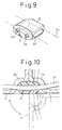
- Fig. 9 is a perspective view of a cable guide in the first embodiment of the invention;
- Fig. 10 is a sectional view of the cable guide in the first embodiment of the invention;
- Fig. 11 is a enlarged partial sectional view of the first embodiment of the invention;
- Fig. 12 is a schematic illustration showing a paper feed path slit in the first embodiment of the invention;
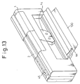
- Fig. 13 is a perspective view of the first embodiment of the invention when in a condition for exchanging the ribbon cassette;
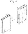
- Fig. 14 is a perspective view of a receptacle cover in the first embodiment of the invention;
- Fig. 15 is a side elevation of the second embodiment of the invention when in a condition of use;
- Fig. 16 is a side elevation of the second embodiment of the invention when in a condition of hand-carrying;
- Fig. 17 is a schematic side elevation of the third embodiment of the invention when in a condition of hand-carrying;
- Fig. 18 is a schematic plan view of the third embodiment of the invention when in a condition of hand-carrying;
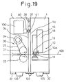
- Fig. 19 is a schematic side elevation of the third embodiment of the invention when in a condition of use.
- An embodiment will be discussed with reference to the drawings.
- Figure 1 through 14 show the first embodiment of the present invention, wherein Figs. 1 to 3 illustrate a condition in which a portable printer is used for printing, and Figs. 4 to 6 illustrate a condition in which the portable printer is not to be used but is to be transported or stored.
- As shown in the respective figures, the portable printer is externally covered with first and second mutually
independent casings casings hinges 3, for a relative pivotal motion thereof with respect to each other. - As shown in Figs. 1 and 5, a
printing mechanism 10 andbatteries 50 are disposed within thefirst casing 1, and apaper feed mechanism 20 and acontrol circuit board 30 are disposed within thesecond casing 2. - The overall construction of the
printing mechanism 10 is housed in thefirst casing 1. Namely, aplaten 11 and aguide shaft 17 parallel thereto are rigidly secured in thefirst casing 1 and acarriage 13 slidably supported on theguide shaft 17 is driven for a reciprocating motion thereof along theguide shaft 17 by aspace motor 15 via adrive belt 16. - A
printing head 12 is mounted on thecarriage 13 in opposition to theplaten 11, and aribbon cassette 14 is detachably mounted on thecarriage 13 such that an inkedribbon 14a lies between theprinting head 12 and theplaten 11. - With this construction, when the
carriage 13 is driven by thespace motor 15, theprinting head 12 travels along theplaten 11, while maintaining the opposing relationship thereof with theplaten 11, to perform a printing of one line. - Further, the overall construction of the
paper feeder mechanism 20 is housed in thesecond casing 2. Namely, three pairs ofpaper feed rollers rotary shafts second casing 2, and among theserollers primary drive rollers 21 are rotatingly driven by aline feed motor 24 via agear mechanism 26. - Furthermore, idling
rollers 22 are rotatably mounted on anarm 28 pivotally supported within thesecond casing 2 for a pivotal motion about ashaft 27. Thearm 28 is biased in a direction represented by the arrow A by aspring 29, and accordingly, the idlingrollers 22 are pressed onto theprimary drive rollers 21 and rotated therewith. Note, thearm 28 and thespring 29 are not shown in Fig. 5. - The
control circuit board 30 fixedly secured within thesecond casing 2, occupies a large space within thesecond casing 2 and outputs a variety of signals to thespace motor 15, theprinting head 12, theline feed motor 24 and so forth, through aflexible cable 31. -
Reference numeral 45 denotes a power switch of the portable printer, arranged in a recess formed in thesecond casing 2 such that it does not project from the surface of thesecond casing 2.Reference numeral 46 shown in Fig. 2 denotes various operation switches for a printing intensity control, line feed, on-line/off-line, and so forth. - The first and
second casings hinges 3, for a relative pivotal movement thereof, whereby the first andsecond casings - While in use, i.e., while performing a printing on a
paper 100 by theprinting mechanism 10, thecasings wider surfaces - At this time, the
casings casings casings casing legs - While not in use, i.e., when carried and transported, the
casings casings - On the external surfaces of the
casings permanent magnet 32 is secured to one of the surfaces and asteel plate 33 is secured to the other surface thereof. Therefore, when in the open position, due to an attraction force between thepermanent magnet 32 and thesteel plate 33, thecasings casings - Even in the open position, the
printing mechanism 10 constituted of theplaten 11 and theprinting head 12 and so forth is not separated but is maintained as one body housed in thefirst casing 1. Therefore, the opposing faces of theplaten 11 and theprinting head 12 and so forth, are not externally exposed. - For a pivotal connection of the
casings axles - As shown in Fig. 8, the
hinges 3 are received inrecesses casings casings first axle 3a is supported on thefirst casing 1 and thesecond axle 3b is supported on thesecond casing 2. Accordingly, thehinges 3 are respectively journaled on thecasings hinges 3 hold thecasings - Furthermore, as shown in Fig. 8, the
recesses casings hinges 3. Accordingly, thehinges 3 are constantly biased by the elastic force of the felt 8, to thereby restrict any free movement thereof and prevent play while in motion, and to eliminate noise. - As shown in Figs. 3, 5 and 6, a
cable guide 9 is provided between thecasings flexible cable 31 is passed therethrough. Thecable guide 9 is extended in parallel to thehinges 3. - As shown in Fig. 9, the
cable guide 9 has essentially the same external configuration as thehinges 3 and forms a dummy hinge (dummy connecting means) journaled on each casing byaxles hinges 3. Thecable guide 9 is separated into upper and lower parts at a straight line extending through the center of theaxles groove 9c is formed on the separated surface and thecable guide 9 is passed through the inner side thereof. - As shown in Fig. 10,
holes respective casings cable guide 9, so that theflexible cable 31 can be passed therethrough. - Accordingly, since the
flexible cable 31 is not externally exposed, an enhanced external appearance can be provided. Furthermore, during an opening and closing of thecasings flexible cable 3 will not be subjected to tension or bending by thecasings flexible cable 31. Also, theflexible cable 31 will not interfere with the opening and closing of thecasings - Returning to Fig. 1, on the
wider surfaces casings permanent magnet 37 is secured to one of the surfaces and asteel strip 38 is secured to the other surface. In the closed position, the attraction force between thepermanent magnet 37 and thesteel strip 38 maintains thecasings casings - It should be noted that, as shown in Fig. 11, the
permanent magnet 37 is provided on the surface of thecasing 2 in a recess therein to avoid a direct contact with other items holding magnetically recorded data, such as a cash card, telephone card and so forth. - On the other hand, the
steel strip 38 is biased inward by aweak spring 39 so that it does not extend from the surface of thecasing 1 in the open position. In the closed position, however, thesteel strip 38 extends from the surface of thecasing 1 against the force of thespring 39, to be engaged with thepermanent magnet 37. - If the
spring 39 has too large a biasing force, and accordingly, thepermanent magnet 37 cannot draw out thesteel strip 38 for engagement, thesteel strip 38 can be moved to the engaged position with thepermanent magnet 37 by a push button not shown. - As shown in Fig. 3, the
legs casings respective legs casings legs legs casings - The
legs casings casings casings projections legs casings - Returning to Fig. 1, the
paper feed paths 7 for feeding thepaper 100 are formed in thecasings casings - In this embodiment, a push-in type paper feed, in which the
paper 100 is fed from thepaper feed mechanism 20 to theprinting mechanism 10, is employed. Note, it is possible to employ a draw type paper feed, in which the paper fedmechanism 20 is positioned downstream of theprinting mechanism 10 with respect to the paper feed direction. - A paper
insertion guide plate 43 is provided at the inlet portion of thepaper feed path 7 of thesecond casing 2, for a free opening and closing. Upon printing, thepaper 100 can be guided along the paperinsertion guide plate 43 in the open position into thepaper feed path 7. - The
paper feed path 7 is designed to pass thepaper 100 between theprimary drive roller 21 and the idlingroller 22 and between theplaten 11 and theprinting head 12.Slits printing paper 100 to pass therethrough are provided in thewider surfaces paper feed paths 7. - As shown in Fig. 12, these
slits slit 7a in thefirst casing 1, which is positioned downstream with respect to the paper feed direction, has a wider opening than theslit 7b of thesecond casing 2 positioned at the upstream side. Here, for example, the width of theslit 7a of thefirst casing 1 is approximately 3 mm and the width of theslit 7b of thesecond casing 2 is approximately 1 mm. - Accordingly, when an offset occurs between the
casings paper 100 in thepaper feed path 7 will not occur, and thus a smooth feed of thepaper 100 from thesecond casing 2 to thefirst casing 1 can be achieved. - It should be noted that it is possible to provide no substantial difference in the widths of the
slits first slit 7a instead. - With the arrangement set forth above, in the closed position, the
paper 100 is driven to run through the paper fendpath 7 by thepaper feed mechanism 20, and printing is performed on the surface of thepaper 100 by theprinting mechanism 100. - Figure 13 shows a
closure lid 44 provided on the outer surface of thefirst casing 1, in the open position. This position is shown by a two dotted line in Fig. 1. - The
closure lid 44 has a size corresponding to the range of travel of theribbon cassette 14 and has a pivot at the lower end thereof. Accordingly, when theclosure lid 44 is open, the upper portion can be widely opened. Theribbon cassette 14 is exposed within the opening, to thus facilitate an exchange of theribbon cassette 14. - Further, since the lower end of the
closure lid 44 forms thepaper ejecting opening 5, theprinting paper 100 is positioned at the lower side of theclosure lid 44 when theclosure lid 44 is open. Accordingly, when theribbon cassette 14 is exchanged midway in the printing operation, thepaper 100 will not be touched, and thus will not be shifted from the printing position. - Figure 14 shows the
receptacle cover 47 for housing theportable printer receptacle cover 47 has a thin box-shaped A4 size configuration and has oneopen side face 47a through which the portable printer in the open position can be accommodated therein and removed therefrom. - Further, a partitioning plate 47b is provided in the
receptacle cover 47, to position the portable printer, and associateditems 48, such as an instruction manual and so forth, separately by the partitioning plate 47b. - When the portable printer is accommodated in the
receptacle cover 47, the carrying and transporting thereof becomes easier and safer. - Figure 15 and 16 show the second embodiment of the invention. In contrast to the above-mentioned first embodiment, the
hinges 3 are provided on the opposite side. Namely, as shown in Fig. 15, in the closed position when placed vertically, thehinges 3 are located at the upper end. The other portions are the same as in the first embodiment. - With such a construction, as shown in Fig. 16, in the closed position, the
power switch 45 is located between thecasings - It should be noted that, in the above-mentioned embodiment, a switching between the use condition (closed portion), in which the
wider surfaces casings casings cases hinges 3, for an opening and closing thereof. It is possible to connect thecasings casings - Figures 17 and 18 show the third embodiment of the portable printer according to the present invention, when in the open position. It should be noted that the same references numerals as in the first embodiment represent the same components.
- In the drawing, 1 denotes the first casing receiving therein the
printing mechanism paper feed mechanism 20. - The
platen 11 is rigidly fixed in thefirst casing 1, and athermal printing head 12 is arranged in opposition to theplaten 11. Theprinting head 12 is detachably mounted on thecarriage 13, as is theribbon cassette 14.Reference numeral 14a denotes the inked ribbon arranged to run from theribbon cassette 14 across the front face of theprinting head 12. - The
carriage 12 is driven by thespace motor 15, through a drive belt, to travel along theguide shaft 17, and accordingly, theprinting head 12 travels along theplaten 11, while maintaining a position opposite to theplaten 11, to perform a printing of one line. -
Reference numeral 4 denotes a pair of side frames for supporting theprinting mechanism 10 within thefirst casing first casing 1 for feeding the paper across the portion between theplaten 11 and theprinting head 12. - Further, in the
second casing 2, a pair ofpaper feed rollers rotary shafts rollers paper feed roller 21 is driven by theline feed motor 24 through thedrive belt 23, and the secondpaper feed roller 22 is pressed onto the firstpaper feed roller 21 by atension coil spring 25. -
Reference numeral 6 denotes a side frame for supporting thepaper feed mechanism 20 within thesecond casing 2, and to denotes a paper feed path defined within the second casing for feeding the paper across the portion between the pair ofpaper feed rollers -
Numeral 130 denotes a control circuit section housed in thesecond casing 2. The control circuit section feeds a variety of signals to thespace motor 15, theprinting head 12, theline feed motor 24 and so forth, through theflexible cable 31, and accordingly, the conductive line will not interfere with the opening and closing of thecasings casings - The first and
second casings hinge joints 103, for a relative pivotal movement thereof, whereby a relative pivoting of thecasings - In the open position as illustrated in Figs. 17 and 18, the first and
second casings - Further, as the
printing mechanism 10 is housed in thefirst casing 1 in a non-separated manner, the important portions, such as the mating surfaces of theplaten 11 and theprinting head 12 and so forth, are not externally exposed. - This open position can be maintained by the
permanent magnet 32 and thesteel plate 33 respectively mounted on the mating portions of thecasings permanent magnet 32 and thesteel plate 33, the open position can be stably maintained. -
Reference 135 denotes platforms forming legs of the portable printer in the closed position, and two are provided for each of thecasings platforms 135 may interfere with each other in the open position, and therefore, thecasings platforms 135 therein and permit a pivotal motion through an angle of 180°. -
Numerals second casings second casing 2 for turning OFF the power at a position other than the closed position, and 41 denotes an actuator projected from thefirst casing 1 for turning ON theswitch 40 in the closed position. At a position other than the closed position, theactuator 41 does not depress theswitch 40, and thus the power for the device is maintained OFF and theprinting head 12, thespace motor 15, theline feed motor 24 and so forth are not activated. - Figure 19 shows the closed position of the portable printer in a further simplified form than that of Fig. 17.
- In the closed position, a gap appears between the
platen 11 and the printing head, and the contacting portions of thepaper feeder rollers paper 100 can be fed between theplaten 11 and theprinting head 12. - Thus, the
platforms 135 serve as legs for supporting the overall construction of the portable printer. The attracting force between the permanent magnet and thesteel strip - Further, as set forth above, the
switch 40 is depressed by theactuator 41 to be released from the OFF position. Therefore, by turning ON a separately provided power switch (not shown), the power for the device can be turned ON. - It should be noted that the present invention should not be limited to the foregoing embodiments. For example, any suitable retaining means other than the permanent magnet can be employed for maintaining the casings in the open and closed positions.
- With the portable printer according to the present invention, the overall structure is separated into a plurality of casings to thereby form a flat configuration convenient for carrying and transporting, which configuration is different from that when the printer is in use, to facilitate the carrying and transporting thereof. Further, during the carrying and transporting of the printer, the printing mechanism is not externally exposed, and therefore, it is not possible to cause damage to or a staining of the printing mechanism, and thus a good printing quality can be reliably maintained for a long time.
Claims (21)
- A portable printer comprising:
a plurality of casings (1, 2);
a printing mechanism (10) housed in the casings (1, 2) for performing a printing operation on paper (100); characterised in that there is provided
connecting means (3) for connecting the plurality of casings (1, 2) by mating wider surfaces (1a and 2a) of the outer surfaces of the casings (1, 2) when a printing of the paper (100) by the printing mechanism (10) is performed; and
when a printing is not performed, the relative positional relationship of the plurality of the casings (1, 2) to one another can be varied to form an essentially flat configuration overall. - A portable printer according to claim 1, wherein the plurality of casings (1, 2) are connected by the connecting means (3) so that the plurality of casings (1, 2) can form the essentially flat configuration overall when a printing of the paper (100) is not performed.
- A portable printer according to claim 2, wherein the connecting means (3) connects the plurality of casings for an opening and closing thereof.
- A portable printer according to claim 3, wherein two casings (1, 2) are provided and the two casings (1, 2) are connected at lower ends thereof by the connecting means (3) when a printing is performed.
- A portable printer according to claim 3 or 4, wherein dummy connecting means (9) performing essentially the same action as the connecting means (3) with respect to each of the casings (1, 2) is provided in parallel to the connecting means (3), and a cable (31) for electrical connection between the plurality of casings (1, 2) is inserted through the dummy connecting means (9).
- A portable printer according to claim 3, 4 or 5, wherein said connecting means (3) comprises a twin axle type hinge pivotally journaled on both of said casings (1, 2) to be connected by said connecting means (3).
- A portable printer as set forth in claim 6, wherein an elastic body (8) is disposed between said twin axle type hinge (3) and said casings (1, 2) for restricting a free motion of said twin axle hinge (3).
- A portable printer as set forth in any one of claims 1 to 7, wherein two casings (1, 2) are provided, said printing mechanism (10) is housed in one of said casings (1), and a paper feed mechanism (20) for feeding said paper (100) is housed in the other casing (2).
- A portable printer as set forth in claim 8, wherein said casing (1) housing therein said printing mechanism (10) is arranged downstream with respect to a feed direction of said paper (100) by said paper feed mechanism (10), and said casing (2) housing said paper feeder mechanism (20) is arranged upstream thereof.
- A portable printer as set forth in any one of claims 1 through 9, wherein condition holding means (37, 38) are provided for maintaining a condition when wider surfaces (1a, 2a) among outer surfaces of said plurality of casings (1, 2) are mated to each other.
- A portable printer as set forth in claim 10, wherein said condition holding means (37, 38) comprises a magnet (37) provided on one of the plurality of adjacent casings (1, 2) and a magnetically conductive member (38) provided on the other casing.
- A portable printer as set forth in claim 11, wherein said magnet (37) provided on one of said casings (2) is recessed from the surface thereof.
- A portable printer as set forth in claim 12, wherein said magnetically conductive member (38) is projectably and retractably provided on the other casing (1) with respect to the surface thereof.
- A portable printer as set forth in any one of claims 1 through 13, wherein a paper feed path (7) for passing said paper (100) therethrough is extended through said two casings (1, 2).
- A portable printer as set forth in claim 14, wherein slits (7a, 7b) are formed through said wider surface (1a, 2a) of said casing at an intermediate position in said paper feed path (7), in alignment with each other, and among said plurality of slits, a slit (7a) positioned downstream with respect to the paper feed direction has a wider opening than a slit (7b) positioned upstream thereof.
- A portable printer as set forth in any one of claims 1 through 15, wherein support means (35, 36) are provided for supporting said casing (1, 2) when stood on a floor while said wider surfaces (1a, 2a) of said plurality of casings (1, 2) are mated to each other.
- A portable printer as set forth in claim 16, wherein said support means (35, 36) is projectably and retractably provided in said casing (1, 2).
- A portable printer as set forth in any one of claims 1 through 17, wherein a ribbon cassette (14) is detachably disposed in said casing (1), in which said printing mechanism (10) is housed, and a closure lid (44) for opening and closing a side wall of said casing (1), for exposing said ribbon cassette (14), is pivotally mounted on said casing (1) to be pivotable about a vicinity of the lower end thereof.
- A portable printer as set forth in claim 1, 2 or 3, wherein a power switch (45) is provided at a position between said casings (1, 2) and is not externally exposed when said casings (1, 2) are in said essentially flat configuration overall.
- A portable printer as set forth in any one of claims 1 through 19, wherein a receptacle cover (47) is provided for receiving said plurality of casings (1, 2) when in said flat configuration.
- A portable printer as set forth in claim 20, wherein a partitioning plate (47a) is provided for said receptacle cover (47), for partitioning said casings (1, 2) and other associated materials (48).
Applications Claiming Priority (5)
| Application Number | Priority Date | Filing Date | Title |
|---|---|---|---|
| JP170669/90 | 1990-06-28 | ||
| JP17066990 | 1990-06-28 | ||
| JP3009403A JP2857498B2 (en) | 1990-06-28 | 1991-01-29 | Portable printer |
| JP9403/91 | 1991-01-29 | ||
| PCT/JP1991/000860 WO1992000197A1 (en) | 1990-06-28 | 1991-06-26 | Portable printer |
Publications (3)
| Publication Number | Publication Date |
|---|---|
| EP0489926A1 EP0489926A1 (en) | 1992-06-17 |
| EP0489926A4 EP0489926A4 (en) | 1992-12-02 |
| EP0489926B1 true EP0489926B1 (en) | 1995-05-10 |
Family
ID=26344118
Family Applications (1)
| Application Number | Title | Priority Date | Filing Date |
|---|---|---|---|
| EP91911945A Expired - Lifetime EP0489926B1 (en) | 1990-06-28 | 1991-06-26 | Portable printer |
Country Status (6)
| Country | Link |
|---|---|
| US (1) | US5236265A (en) |
| EP (1) | EP0489926B1 (en) |
| JP (1) | JP2857498B2 (en) |
| KR (1) | KR960013671B1 (en) |
| DE (1) | DE69109638T2 (en) |
| WO (1) | WO1992000197A1 (en) |
Families Citing this family (54)
| Publication number | Priority date | Publication date | Assignee | Title |
|---|---|---|---|---|
| JP2984066B2 (en) * | 1991-01-29 | 1999-11-29 | 富士通アイソテック株式会社 | Automatic paper feeder for printer |
| GB2268708B (en) * | 1992-07-01 | 1995-12-13 | Seiko Epson Corp | Compact printer |
| ATE180719T1 (en) * | 1992-09-29 | 1999-06-15 | Canon Kk | APPARATUS FOR PAPER SUPPLY |
| CA2127198A1 (en) * | 1993-07-01 | 1995-01-02 | Darald R. Schultz | Portable compact multi-function printer with cartridge paper supply |
| US5411339A (en) * | 1993-12-09 | 1995-05-02 | Kroy, Inc. | Portable printer and cartridge therefor |
| JPH1029345A (en) * | 1996-07-16 | 1998-02-03 | Brother Ind Ltd | Printing device |
| JPH11301060A (en) * | 1998-04-15 | 1999-11-02 | Canon Inc | Recording device and sheet material transport device |
| AUPQ056099A0 (en) * | 1999-05-25 | 1999-06-17 | Silverbrook Research Pty Ltd | A method and apparatus (pprint01) |
| US7384134B2 (en) * | 1999-05-25 | 2008-06-10 | Silverbrook Research Pty Ltd | Ink cartridge with collapsible ink containers for an inkjet printer |
| USD440246S1 (en) | 2000-02-22 | 2001-04-10 | Hewlett-Packard Company | Printer |
| US6530475B1 (en) | 2000-06-07 | 2003-03-11 | Joseph J. Penney | Portable office |
| CN2515702Y (en) * | 2001-12-30 | 2002-10-09 | 黄秀臣 | Laser printing manuscript black-increasing device |
| KR100534615B1 (en) * | 2004-03-15 | 2005-12-07 | 삼성전자주식회사 | Image forming apparatus having foldable paper cassette |
| USD542794S1 (en) * | 2005-09-06 | 2007-05-15 | Lite-On Technology Corporation | Thin scanning and printing device |
| US7500732B2 (en) * | 2005-09-30 | 2009-03-10 | Lexmark International, Inc. | Maintenance and docking station for a hand-held printer |
| US20070076082A1 (en) * | 2005-09-30 | 2007-04-05 | Lexmark International, Inc. | Methods and apparatuses for measuring print area using hand-held printer |
| US7735951B2 (en) * | 2005-11-15 | 2010-06-15 | Lexmark International, Inc. | Alignment method for hand-operated printer |
| US20070120937A1 (en) * | 2005-11-30 | 2007-05-31 | Lexmark International, Inc. | System and method for hand-held printing |
| US7524051B2 (en) * | 2005-12-20 | 2009-04-28 | Lexmark International, Inc. | Hand-operated printer having a user interface |
| US7399129B2 (en) * | 2005-12-20 | 2008-07-15 | Lexmark International, Inc. | User interface for a hand-operated printer |
| US20070237561A1 (en) * | 2006-04-11 | 2007-10-11 | Lexmark International Inc. | Methods and apparatuses for sensing a print area using a hand-held printer |
| US7748839B2 (en) * | 2006-05-09 | 2010-07-06 | Lexmark International, Inc. | Handheld printing with reference indicia |
| US7682017B2 (en) * | 2006-05-10 | 2010-03-23 | Lexmark International, Inc. | Handheld printer minimizing printing defects |
| USD558261S1 (en) * | 2006-06-06 | 2007-12-25 | Samsung Electronics Co., Ltd. | Printer |
| DE102006026446B4 (en) * | 2006-06-07 | 2009-02-26 | Pierburg Gmbh | Cover for an actuator with a punched grid as a hinge |
| US7787145B2 (en) * | 2006-06-29 | 2010-08-31 | Lexmark International, Inc. | Methods for improving print quality in a hand-held printer |
| USD563413S1 (en) * | 2006-07-05 | 2008-03-04 | Pfu Limited | Scanner |
| US20080030534A1 (en) * | 2006-08-02 | 2008-02-07 | Adam Jude Ahne | Hand Held Micro-fluid Ejection Devices Configured to Eject Fluid without Referential Position Information and Method of Ejecting Fluid |
| US20080079956A1 (en) * | 2006-09-21 | 2008-04-03 | Mahesan Chelvayohan | Hand-Held Printer Having An Integrated Digital Camera Scanner |
| US20080075513A1 (en) * | 2006-09-26 | 2008-03-27 | Douglas Laurence Robertson | Methods for a Maintenance Algorithm in Hand Held Printers |
| US7918519B2 (en) | 2006-09-27 | 2011-04-05 | Lexmark International, Inc. | Methods and apparatus for handheld printing with optical positioning |
| US7938531B2 (en) | 2006-09-27 | 2011-05-10 | Lexmark International, Inc. | Methods and apparatus for handheld printing with optical positioning |
| US7748840B2 (en) * | 2006-09-27 | 2010-07-06 | Lexmark International, Inc. | Methods and apparatus for handheld printing with optical positioning |
| US7938532B2 (en) | 2007-02-16 | 2011-05-10 | Lexmark International, Inc. | Hand held printer with vertical misalignment correction |
| US20080219737A1 (en) * | 2007-03-07 | 2008-09-11 | Michael David Stilz | Hand Held Printer Having A Doppler Position Sensor |
| US8092006B2 (en) | 2007-06-22 | 2012-01-10 | Lexmark International, Inc. | Handheld printer configuration |
| US20090040286A1 (en) * | 2007-08-08 | 2009-02-12 | Tan Theresa Joy L | Print scheduling in handheld printers |
| USD644265S1 (en) * | 2010-03-01 | 2011-08-30 | Brother Industries, Ltd. | Printer |
| USD643039S1 (en) * | 2010-12-08 | 2011-08-09 | Hewlett-Packard Development Company, L.P. | Multi-function imaging and printing device |
| USD689867S1 (en) * | 2011-08-09 | 2013-09-17 | Canon Denshi Kabushiki Kaisha | Scanner |
| USD682834S1 (en) * | 2011-09-21 | 2013-05-21 | Canon Denshi Kabushiki Kaisha | Scanner |
| USD699726S1 (en) * | 2012-10-19 | 2014-02-18 | Brother Industries, Ltd. | Scanner |
| USD709071S1 (en) * | 2012-11-06 | 2014-07-15 | Canon Denshi Kabushiki Kaisha | Scanner |
| USD706269S1 (en) * | 2012-12-13 | 2014-06-03 | Hewlett-Packard Development Company, L.P. | Imaging device |
| USD714290S1 (en) * | 2012-12-21 | 2014-09-30 | Brother Industries, Ltd. | Scanner |
| USD714291S1 (en) * | 2012-12-21 | 2014-09-30 | Brother Industries, Ltd. | Scanner |
| KR101691813B1 (en) * | 2014-04-14 | 2017-01-02 | 정익승 | Photo printing equipment case |
| USD723035S1 (en) * | 2014-04-15 | 2015-02-24 | Pfu Limited | Scanner |
| JP1523408S (en) * | 2014-10-22 | 2015-05-18 | ||
| USD898029S1 (en) * | 2017-05-02 | 2020-10-06 | Avision Inc. | Paper support |
| JP1598197S (en) * | 2017-10-31 | 2019-02-18 | ||
| USD867366S1 (en) * | 2018-01-18 | 2019-11-19 | Seiko Epson Corporation | Scanner |
| EP3566876B1 (en) * | 2018-05-08 | 2020-08-26 | APS Trading OOD | Compact thermal printing mechanism |
| USD913287S1 (en) * | 2019-02-28 | 2021-03-16 | Brother Industries, Ltd. | Scanner |
Citations (4)
| Publication number | Priority date | Publication date | Assignee | Title |
|---|---|---|---|---|
| JPS53157639U (en) * | 1977-05-17 | 1978-12-11 | ||
| JPS55134644U (en) * | 1979-03-15 | 1980-09-25 | ||
| JPS62134154U (en) * | 1986-02-14 | 1987-08-24 | ||
| JPH0245199A (en) * | 1988-08-08 | 1990-02-15 | Fuji Photo Film Co Ltd | Recorder |
Family Cites Families (20)
| Publication number | Priority date | Publication date | Assignee | Title |
|---|---|---|---|---|
| FR415608A (en) * | 1910-02-23 | 1910-09-30 | Chardson | Typewriter Improvements |
| US1246203A (en) * | 1916-08-19 | 1917-11-13 | Southwell Willman | Type-writer desk-case. |
| CH287235A (en) * | 1950-05-06 | 1952-11-30 | Aug Birchmeier S Soehne | Cases for typewriters. |
| CH491749A (en) * | 1969-05-03 | 1970-06-15 | Olivetti & Co Spa | Portable typewriter with briefcase |
| US3940758A (en) * | 1974-09-20 | 1976-02-24 | Margolin George D | Expandable keyboard for electronic pocket calculators and the like |
| JPS5695848U (en) * | 1979-12-25 | 1981-07-29 | ||
| JPS58194046U (en) * | 1982-06-21 | 1983-12-23 | セイコーインスツルメンツ株式会社 | foldable electronic typewriter |
| EP0137715B1 (en) * | 1983-09-12 | 1988-01-07 | Tokyo Electric Co. Ltd. | Printer |
| US4645275A (en) * | 1984-06-28 | 1987-02-24 | Pucci Philip D | Portable carrying case and sound shield for a printer with a self-contained support stand |
| JPS6174870A (en) * | 1984-09-20 | 1986-04-17 | Matsushita Electric Ind Co Ltd | portable typewriter |
| JPS61112942U (en) * | 1984-12-27 | 1986-07-17 | ||
| JPS60170858U (en) * | 1985-02-28 | 1985-11-12 | キヤノン株式会社 | opening/closing body |
| US4725157A (en) * | 1985-07-29 | 1988-02-16 | Brother Kogyo Kabushiki Kaisha | Printing device with a pair of housings combined for relative rocking motion |
| JPS62134154A (en) * | 1985-12-06 | 1987-06-17 | Kawasaki Steel Corp | Cooling method for centrifugal casting mold |
| JPS63238A (en) * | 1986-06-20 | 1988-01-05 | 森永製菓株式会社 | Hydroponic cultivation method of peanuts and equipment used for said hydroponic cultivation |
| JPS6360772A (en) * | 1986-09-02 | 1988-03-16 | Asutaa Seiki Kk | Printer |
| JPS63197682A (en) * | 1987-02-13 | 1988-08-16 | Hitachi Ltd | personal word processor |
| JPH01100218U (en) * | 1987-12-22 | 1989-07-05 | ||
| US5105210A (en) * | 1988-05-18 | 1992-04-14 | Canon Kabushiki Kaisha | Ink jet recording apparatus expandable to accommodate variable sheet widths |
| US5111216A (en) * | 1988-07-12 | 1992-05-05 | Kroy Inc. | Tape supply cartridge for portable thermal printer |
-
1991
- 1991-01-29 JP JP3009403A patent/JP2857498B2/en not_active Expired - Fee Related
- 1991-06-26 DE DE69109638T patent/DE69109638T2/en not_active Expired - Fee Related
- 1991-06-26 KR KR1019920700459A patent/KR960013671B1/en not_active Expired - Fee Related
- 1991-06-26 WO PCT/JP1991/000860 patent/WO1992000197A1/en not_active Ceased
- 1991-06-26 US US07/836,292 patent/US5236265A/en not_active Expired - Fee Related
- 1991-06-26 EP EP91911945A patent/EP0489926B1/en not_active Expired - Lifetime
Patent Citations (4)
| Publication number | Priority date | Publication date | Assignee | Title |
|---|---|---|---|---|
| JPS53157639U (en) * | 1977-05-17 | 1978-12-11 | ||
| JPS55134644U (en) * | 1979-03-15 | 1980-09-25 | ||
| JPS62134154U (en) * | 1986-02-14 | 1987-08-24 | ||
| JPH0245199A (en) * | 1988-08-08 | 1990-02-15 | Fuji Photo Film Co Ltd | Recorder |
Also Published As
| Publication number | Publication date |
|---|---|
| DE69109638T2 (en) | 1995-09-07 |
| US5236265A (en) | 1993-08-17 |
| KR960013671B1 (en) | 1996-10-10 |
| EP0489926A4 (en) | 1992-12-02 |
| JP2857498B2 (en) | 1999-02-17 |
| EP0489926A1 (en) | 1992-06-17 |
| KR920702294A (en) | 1992-09-03 |
| WO1992000197A1 (en) | 1992-01-09 |
| JPH0615917A (en) | 1994-01-25 |
| DE69109638D1 (en) | 1995-06-14 |
Similar Documents
| Publication | Publication Date | Title |
|---|---|---|
| US5236265A (en) | Portable printer with variable housing configurations | |
| US8297611B2 (en) | Image recording apparatus | |
| JP2004268207A (en) | Scissor-type recording paper cutting device and printer | |
| JPH05211399A (en) | Small electronic equipment portable fixing device | |
| JP2023063903A (en) | printer | |
| KR101870439B1 (en) | Recording medium processing apparatus | |
| US10654296B2 (en) | Printing apparatus | |
| KR20160076476A (en) | Printing apparatus | |
| JP7451991B2 (en) | recording device | |
| US20050285330A1 (en) | Multipurpose tray | |
| US12252372B2 (en) | Medium transport apparatus | |
| CA1316555C (en) | Compact printer with adjustable sheet storage cassette | |
| CN113165401B (en) | Ink cartridge | |
| CA1320384C (en) | Compact printer having improved sheet cassette | |
| JP4768169B2 (en) | Printer | |
| US6904250B2 (en) | Image forming apparatus | |
| US20250150542A1 (en) | Image forming device | |
| US12145384B2 (en) | Printing apparatus | |
| JP2663952B2 (en) | Portable printer | |
| JPH06286266A (en) | Printer | |
| JP3408128B2 (en) | Recording device | |
| JP6443286B2 (en) | Electronics | |
| JP2008154089A (en) | Image forming apparatus | |
| JP2025025475A (en) | Image forming device | |
| JP2576008B2 (en) | Printer |
Legal Events
| Date | Code | Title | Description |
|---|---|---|---|
| PUAI | Public reference made under article 153(3) epc to a published international application that has entered the european phase |
Free format text: ORIGINAL CODE: 0009012 |
|
| 17P | Request for examination filed |
Effective date: 19920312 |
|
| AK | Designated contracting states |
Kind code of ref document: A1 Designated state(s): DE FR GB |
|
| A4 | Supplementary search report drawn up and despatched |
Effective date: 19921012 |
|
| AK | Designated contracting states |
Kind code of ref document: A4 Designated state(s): DE FR GB |
|
| 17Q | First examination report despatched |
Effective date: 19940331 |
|
| GRAA | (expected) grant |
Free format text: ORIGINAL CODE: 0009210 |
|
| AK | Designated contracting states |
Kind code of ref document: B1 Designated state(s): DE FR GB |
|
| REF | Corresponds to: |
Ref document number: 69109638 Country of ref document: DE Date of ref document: 19950614 |
|
| ET | Fr: translation filed | ||
| PLBE | No opposition filed within time limit |
Free format text: ORIGINAL CODE: 0009261 |
|
| STAA | Information on the status of an ep patent application or granted ep patent |
Free format text: STATUS: NO OPPOSITION FILED WITHIN TIME LIMIT |
|
| 26N | No opposition filed | ||
| PGFP | Annual fee paid to national office [announced via postgrant information from national office to epo] |
Ref country code: FR Payment date: 19980609 Year of fee payment: 8 |
|
| PGFP | Annual fee paid to national office [announced via postgrant information from national office to epo] |
Ref country code: GB Payment date: 19980617 Year of fee payment: 8 |
|
| PGFP | Annual fee paid to national office [announced via postgrant information from national office to epo] |
Ref country code: DE Payment date: 19980706 Year of fee payment: 8 |
|
| PG25 | Lapsed in a contracting state [announced via postgrant information from national office to epo] |
Ref country code: GB Free format text: LAPSE BECAUSE OF NON-PAYMENT OF DUE FEES Effective date: 19990626 |
|
| PG25 | Lapsed in a contracting state [announced via postgrant information from national office to epo] |
Ref country code: FR Free format text: THE PATENT HAS BEEN ANNULLED BY A DECISION OF A NATIONAL AUTHORITY Effective date: 19990630 |
|
| GBPC | Gb: european patent ceased through non-payment of renewal fee |
Effective date: 19990626 |
|
| PG25 | Lapsed in a contracting state [announced via postgrant information from national office to epo] |
Ref country code: DE Free format text: LAPSE BECAUSE OF NON-PAYMENT OF DUE FEES Effective date: 20000503 |
|
| REG | Reference to a national code |
Ref country code: FR Ref legal event code: ST |