EP0489835B1 - Ticket dispenser - Google Patents
Ticket dispenser Download PDFInfo
- Publication number
- EP0489835B1 EP0489835B1 EP90913563A EP90913563A EP0489835B1 EP 0489835 B1 EP0489835 B1 EP 0489835B1 EP 90913563 A EP90913563 A EP 90913563A EP 90913563 A EP90913563 A EP 90913563A EP 0489835 B1 EP0489835 B1 EP 0489835B1
- Authority
- EP
- European Patent Office
- Prior art keywords
- ticket
- strip
- feeder
- assembly according
- roll
- Prior art date
- Legal status (The legal status is an assumption and is not a legal conclusion. Google has not performed a legal analysis and makes no representation as to the accuracy of the status listed.)
- Expired - Lifetime
Links
- 239000011324 bead Substances 0.000 claims description 17
- 239000000463 material Substances 0.000 claims description 4
- 230000000149 penetrating effect Effects 0.000 description 2
- 230000000712 assembly Effects 0.000 description 1
- 238000000429 assembly Methods 0.000 description 1
- 230000000295 complement effect Effects 0.000 description 1
- 239000004020 conductor Substances 0.000 description 1
- 238000010276 construction Methods 0.000 description 1
- 230000001419 dependent effect Effects 0.000 description 1
- 238000001514 detection method Methods 0.000 description 1
- 230000000694 effects Effects 0.000 description 1
- 230000000284 resting effect Effects 0.000 description 1
- 238000000926 separation method Methods 0.000 description 1
Images


Classifications
-
- B—PERFORMING OPERATIONS; TRANSPORTING
- B65—CONVEYING; PACKING; STORING; HANDLING THIN OR FILAMENTARY MATERIAL
- B65C—LABELLING OR TAGGING MACHINES, APPARATUS, OR PROCESSES
- B65C11/00—Manually-controlled or manually-operable label dispensers, e.g. modified for the application of labels to articles
-
- G—PHYSICS
- G07—CHECKING-DEVICES
- G07B—TICKET-ISSUING APPARATUS; FARE-REGISTERING APPARATUS; FRANKING APPARATUS
- G07B3/00—Machines for issuing preprinted tickets
- G07B3/02—Machines for issuing preprinted tickets from stock in wound strip form
-
- Y—GENERAL TAGGING OF NEW TECHNOLOGICAL DEVELOPMENTS; GENERAL TAGGING OF CROSS-SECTIONAL TECHNOLOGIES SPANNING OVER SEVERAL SECTIONS OF THE IPC; TECHNICAL SUBJECTS COVERED BY FORMER USPC CROSS-REFERENCE ART COLLECTIONS [XRACs] AND DIGESTS
- Y10—TECHNICAL SUBJECTS COVERED BY FORMER USPC
- Y10S—TECHNICAL SUBJECTS COVERED BY FORMER USPC CROSS-REFERENCE ART COLLECTIONS [XRACs] AND DIGESTS
- Y10S428/00—Stock material or miscellaneous articles
- Y10S428/906—Roll or coil
-
- Y—GENERAL TAGGING OF NEW TECHNOLOGICAL DEVELOPMENTS; GENERAL TAGGING OF CROSS-SECTIONAL TECHNOLOGIES SPANNING OVER SEVERAL SECTIONS OF THE IPC; TECHNICAL SUBJECTS COVERED BY FORMER USPC CROSS-REFERENCE ART COLLECTIONS [XRACs] AND DIGESTS
- Y10—TECHNICAL SUBJECTS COVERED BY FORMER USPC
- Y10T—TECHNICAL SUBJECTS COVERED BY FORMER US CLASSIFICATION
- Y10T225/00—Severing by tearing or breaking
- Y10T225/20—Severing by manually forcing against fixed edge
- Y10T225/205—With feed-out of predetermined length from work supply
- Y10T225/207—Including feed-out stop for manually pulled work
- Y10T225/208—Stop abuts work edge or work-mounted article
-
- Y—GENERAL TAGGING OF NEW TECHNOLOGICAL DEVELOPMENTS; GENERAL TAGGING OF CROSS-SECTIONAL TECHNOLOGIES SPANNING OVER SEVERAL SECTIONS OF THE IPC; TECHNICAL SUBJECTS COVERED BY FORMER USPC CROSS-REFERENCE ART COLLECTIONS [XRACs] AND DIGESTS
- Y10—TECHNICAL SUBJECTS COVERED BY FORMER USPC
- Y10T—TECHNICAL SUBJECTS COVERED BY FORMER US CLASSIFICATION
- Y10T225/00—Severing by tearing or breaking
- Y10T225/20—Severing by manually forcing against fixed edge
- Y10T225/238—With housing for work supply
- Y10T225/252—With brake or tensioner
- Y10T225/253—Restricted or restrictable work outlet
-
- Y—GENERAL TAGGING OF NEW TECHNOLOGICAL DEVELOPMENTS; GENERAL TAGGING OF CROSS-SECTIONAL TECHNOLOGIES SPANNING OVER SEVERAL SECTIONS OF THE IPC; TECHNICAL SUBJECTS COVERED BY FORMER USPC CROSS-REFERENCE ART COLLECTIONS [XRACs] AND DIGESTS
- Y10—TECHNICAL SUBJECTS COVERED BY FORMER USPC
- Y10T—TECHNICAL SUBJECTS COVERED BY FORMER US CLASSIFICATION
- Y10T225/00—Severing by tearing or breaking
- Y10T225/30—Breaking or tearing apparatus
- Y10T225/393—Web restrainer
-
- Y—GENERAL TAGGING OF NEW TECHNOLOGICAL DEVELOPMENTS; GENERAL TAGGING OF CROSS-SECTIONAL TECHNOLOGIES SPANNING OVER SEVERAL SECTIONS OF THE IPC; TECHNICAL SUBJECTS COVERED BY FORMER USPC CROSS-REFERENCE ART COLLECTIONS [XRACs] AND DIGESTS
- Y10—TECHNICAL SUBJECTS COVERED BY FORMER USPC
- Y10T—TECHNICAL SUBJECTS COVERED BY FORMER US CLASSIFICATION
- Y10T428/00—Stock material or miscellaneous articles
- Y10T428/15—Sheet, web, or layer weakened to permit separation through thickness
-
- Y—GENERAL TAGGING OF NEW TECHNOLOGICAL DEVELOPMENTS; GENERAL TAGGING OF CROSS-SECTIONAL TECHNOLOGIES SPANNING OVER SEVERAL SECTIONS OF THE IPC; TECHNICAL SUBJECTS COVERED BY FORMER USPC CROSS-REFERENCE ART COLLECTIONS [XRACs] AND DIGESTS
- Y10—TECHNICAL SUBJECTS COVERED BY FORMER USPC
- Y10T—TECHNICAL SUBJECTS COVERED BY FORMER US CLASSIFICATION
- Y10T428/00—Stock material or miscellaneous articles
- Y10T428/19—Sheets or webs edge spliced or joined
- Y10T428/192—Sheets or webs coplanar
- Y10T428/197—Sheets or webs coplanar with noncoplanar reinforcement
- Y10T428/198—Pile or nap surface sheets connected
Definitions
- the present invention relates to a ticket dispensing assembly comprising a ticket feeder and a flexible strip of tickets in roll form.
- the ticket feeder functions to enable tickets to be torn invidually from the ticket strip and comprises a casing in which the ticket roll is housed, at least one cover part which is connected pivotally to the casing, and a guide path which is operative to guide a length of continuous strip of tickets taken from the ticket roll.
- the free end of the continuous strip projects through an outfeed opening in the ticket feeder and serves as a fingergrip by means of which the strip can be pulled from the roll.
- Means are also provided which, as the free end of the strip is pulled, function to mutually separate parts of strip material which are located between two mutually adjacent tickets and which hold said tickets together.
- the continuous strip has punched at regular intervals therealong parting lines which define a plurality of tongue-shaped flaps and "flap apertures" and those material parts which hold two mutually adjacent tickets together are located at the ends of respective parting lines and extend approximatly transversly to the longitudinal axis of the strip.
- An assembly comprising a ticket feeder and a continuous ticket strip of this kind, for instance queue tickets, is known from each of US Patent specifications 4,047,652 and 3,885,724.
- the ticket roll used with these known assemblies comprises a flexible, continuous ticket strip in which respective tickets have punched therein penetrating tongue-shaped flaps which when a ticket located in the outfeed aperture is pulled manually, are brought into contact with guide means, through the medium of a feed path.
- the guide means functions to guide a tongue-shaped flap in one direction and the remainder of the strip in another direction.
- a further drawback is that the known feeder is only able to accommodate rolls of at most one thousand tickets.
- Another object of the invention is to provide an improved assembly in which the ticket feeder is able to readily accommodate a ticket roll that contains up to five thousand tickets.
- a ticket feeder 10 which accommodates in roll form a flexible and continuous strip of tickets and which functions to separate the tickets one from the other when the strip is pulled manually.
- the ticket feeder includes a casing 11 and an attachment part 12 which is connected firmly to the casing and by means of which the ticket feeder can be removeably attached to an appropriate wall attachment (not shown).
- the attachment part 12 which is shown partly in section in Fig 2 and from above in Fig 3, is detachably connected to vertically spaced and rearwardly projecting lugs 13, each of which has a pivot pin 14.
- the ticket feeder 10 can therewith pivot on the pin 14 and the attachment part 12 has vertical surfaces 15, 16 which form abutments operative to limit the extent of said pivotal movement.
- a relatively stiff spring 17 mounted horizontally within the attachment part 12 funtions to return the ticket feeder 10 to the position shown in Fig 3, in which the feeder 10 and the attachment part 12 lie essentially in one and the same horizontal plane, subsequent to pivoting said ticket feeder.
- the casing 11 of the ticket feeder 10 comprises a first, upper cover part 18 which is pivotally mounted on a pivot connection 19 described in more detail herebelow.
- the purpose of the upwardly pivotable cover part 18 is to enable the upper part of the ticket feeder 10 to be exposed so that a ticket roll 20 (Fig 1) can be introduced into the casing 11, said roll 20 normally comprising 4000-5000 tickets in continuous strip form wound on a bobbin, such as to form said ticket roll.
- the reference numeral 11b in Fig 2 identifies an internal limiting wall which is positioned so that if the ticket roll should begin to rotate when the free flap on the continuous ticket strip is pulled, the continuous strip would also unwind from the roll. This unwinding of the strip from the roll is limited and controlled by the wall part 11b in a manner such that any lengths of strip that might unwind from the roll will take an S-shape, which would not disturb normal use of the assembly.
- the improved ticket feeder 10 is provided with a second, lower cover part 21 on the same side of the casing as the first cover part 18.
- This second cover part 21 can be swung downwards about a lower hinge means 22.
- a ticket-strip outfeed part Arranged at the top of the casing 11 of the illustrated ticket feeder, and to the left in Figures 1 and 2, is a ticket-strip outfeed part, which will now be described.
- the undivided side of the casing 11 has an elongated ticket path which extends substantially in the direction in which the strip is pulled and the end of which located nearest the roll 20 is curved or gently rounded.
- the centre of the roll 20 preferably lies in the same, or approxamatly the same plane as the free end of the ticket feed path.
- the ticket-feed path presents a horizontal, first smooth feed surface 24 which merges with a second feed surface 26 (Fig 6) which slopes downwardly towards the outfeed aperture 25 and which is terminated with a first lip 27, said lip being slightly curved in the case of the illustrated embodiment.
- the sloping surface 26 of the feed path is located essentially in the extension of an optimum ticket-strip pulling direction, and the actual outfeed aperture 25 is located on a lower plane than the lowest point of the sloping feed surface 26, the horizontal, upper surface of the lip 27 forming a support for a part of the flap on the free end or outermost end of the ticket strip.
- a bead 28 which extends across the guide surface 26.
- the bead 28 resembles the end of a ski-jump construction, i.e. the bead 28 extends slightly upwards at its junction with the guide surface 26 and then drops almost vertically downwards to join the lip 27.
- the width extension of the bead 28 corresponds approximately to the width A (Fig 7) of a ticket.
- Extending on respective sides of the bead 28 are surfaces 29 which lie in substantially the same plane as the bottom surface 26 of the feed path and which merge with the lip 27.
- the bottom guide surface 24, 26 of the feed path has a width which is at least equal to the largest width of the ticket strip.
- the downwardly sloping surface 26 of the feed path is provided along one edge region thereof with a transparent window 30, the function of which is described herebelow (Fig 3).
- the aforedescribed outfeed part of the ticket feeder constitutes means for guiding and feeding the continuous ticket strip taken off the roll 20.
- the ticket feed path 24, 26 is surrounded in its longitudunal direction by mutually opposing wall parts 31, of which one is removably attached.
- respective wall parts 31 are provided with an outwardly extending pin 32 (e.g. Fig 3) which forms the aforesaid pivot attachment 19 for the upper cover part 18.
- Each of said wall parts 31 is also provided with a groove 33 which extends in the longitudinal direction of the feed path and widens towards the outfeed aperture 25.
- the grooves 33 are spaced from the upper edge surface of respective walls 31 and function as guide means for the sides of an elongated slide 34 which is mounted for limited movement in the longitudinal direction of the ticket strip.
- the under surface 35 of the slide 34 functions as second guide means for the ticket strip, said strip being intended to be fed between the mutually opposing guide surfaces 26 and 35, these surfaces together forming the feed path.
- the guide surface 35 of the slide 34 merges with a downwardly and rearwardly extending second lip 37 in the region of the ticket outfeed aperture.
- the end or tip of the lip 37 is rounded and is localised at a small distance from the upwardly facing surface of the outfeed or guide lip 27 on the casing 11, such as to form a slot through which the ticket strip is fed.
- the bottom surface of the slide 34 which forms the top guide surface 35 of the feed path, is also configured so that the feed path widens in a direction towards the outfeed 25 of the ticket feeder to form a larger gap 36 (Fig 4), although solely within the approximate region of the bead 28 on the guide surface 26.
- the aforementioned edge-margin surfaces 29 are not included in the gap widening.
- a relatively wide gap is formed between the upper end of the bead 28 and the region in which the guide surface 35 on the slide 34 changes direction and merges with the lip 37, which in the ticket-feeding state of the ticket feeder 10 terminates immediately beneath the side of the bead 28 which faces the outfeed aperture 25.
- the upper part of the slide 34 is configured with an upwardly open recess 38 and with a rearward, inclined wall 38a.
- the ticket feeder 10 includes a pull spring 39 which is attached at one end to a pin 40 in the slide 34 and at the other end to a pin in the wall part 31 located on the same side. A corresponding arrangement is found on the opposite side.
- Fig 5 is a view of the inside of the cover part 18.
- the cover part includes a member 41 which is complementary in shape to the shape of the recess 38 in the slide 34. Consequently, when a raised cover part (fig 4) is lowered, the member 41 will engage the recess 38 and force the slide 34 to move rearwards against the action of the spring 39, to the position shown in Fig 4.
- the slide 34 is moved forwards by the spring 39 to a passive position (fig 6) in which, for instance, a new ticket roll can be inserted into the feeder (after lowering the cover part 21) and brought between and into coaction with the guide surfaces 26 and 35 of the feed path.
- the slide 34 can be removed, by dismantling the removable wall part 31.
- the detector device 43 is positioned beneath the transparent part 30 in the bottom ticket guide surface 26 and can, in one embodiment, comprises a circuit card comprising an IR diode and a reciever.
- An electrical conductor (not shown) connects the detector device with a microprocessor provided with an internal and/or external display which informs personnel of, for instance, the number of people queuing for service, thereby enabling additional service personnel to be called upon if necessary.
- the display can also be made to show the expected waiting time. Other internal and/or external information functions are possible, of course.
- Each individual ticket in the continuous ticket strip has a colour marking provided on its undersurface and on one edge margin thereof, this colour marking being readable by the detector.
- each fifth ticket may be provided with a colour marking which differs from the colour marking of the four immediately preceding or the four immediately following markings.
- the arrangement may be such as to detect the first mentioned colour marking and to send a corresponding signal, for instance, to a counter, so as to provide internal information of the number of customers served and information concerning the number of queuing customers, so that additional service personnel can be called upon when necessary.
- Such a detection arrangement can also function to indicate to a customer the expected waiting time before he/she is attended to. Other internal/external information can also be given, depending upon the sophistication of the electronic equipment used.
- the continuous ticket strip in roll form used in conjunction with the aforedescribed ticket feeder is comparable with the ticket strip illustrated and described in the aforesaid US-A-4,047,652.
- Fig 7 illustrates a part of the continuous ticket strip, which is assumed to have been unwound from the ticket roll 20.
- This continuous strip of tickets has punched therealong in mutually uniform relationship and in a known manner a number of penetrating lines 44a, 44b such as to form tongue-shaped flaps 45 and correspondingly configured flap openings 46.
- the flaps 45 and the flap openings 46 can be given a configuration different to that shown, depending, among other things, on the width of the ticket strip.
- Distinct from the ticket strip according to US-A-4,047,652 none of the inventive flaps 45 is fully formed, since the centre of the ultimate flap is connected with the ultimate flap opening 46 by a small bridge 50, as shown in fig 7.
- each individual ticket when separated from the strip each individual ticket will present at its forward end a tongue-shaped flap 45, which may have any desired configuration, whereas the rear end of the ticket will present a recess corresponding to and accommodating the flap of the immediatly following ticket and thus forming a flap opening 46.
- the tongue-shaped flap of each individual ticket is connected to the continuous strip along the greatest width 47 of the flap 45.
- This connecting part 47 of each flap extends preferably at right angles to the longitudinal axis of the strip and terminates short of mutually opposite side edges, to form shoulders 48, 49, the width of these shoulders being dependent on the shape of the flap.
- a ticket roll 20 is mounted in the feeder in the manner illustrated in Fig 2.
- the continuous ticket strip indicated in Fig 2 - is passed over a rounded end of the feed path surface 24 and into the gap 36, defined between the guide surfaces 26 and 35 of said path (Fig 4).
- a ticket flap or tongue 45 will protrude beyond the outfeed aperture 25 of the feeder 10, ready to be gripped and pulled.
- the forward end of the flap thus released will, in this stage, be located immediately outside the outfeed aperture 25 of the feeder 10, and the flap will strive to move upwards towards the widened space approximatly at the point X in Fig 6 while the rearward part of the flap will be "folded” slightly, which causes a very short interruption in the forward movement of the ticket strip.
- the pulling action will now be transferred to the shoulders 48, 49, which therewith rapture and release the ticket while leaving the newly exposed tongue-shaped flap of the following ticket in the outfeed aperture so that the flap can be gripped and a further ticket torn from the strip in the aforedescribed manner.
- the described ticket feeder operative to deliver individual tickets from a continuous ticket strip affords the important advantage that the free ticket-tongue protruding from the outfeed aperture 25 can, in practise, be pulled forwards at any conceivable angle without impairing the ticket dispensing function of the feeder 10.
Landscapes
- Physics & Mathematics (AREA)
- General Physics & Mathematics (AREA)
- Ticket-Dispensing Machines (AREA)
- Vending Machines For Individual Products (AREA)
- Credit Cards Or The Like (AREA)
- Devices For Checking Fares Or Tickets At Control Points (AREA)
- Adhesives Or Adhesive Processes (AREA)
- Coupling Device And Connection With Printed Circuit (AREA)
- Eye Examination Apparatus (AREA)
- Replacement Of Web Rolls (AREA)
- Unwinding Webs (AREA)
- Advancing Webs (AREA)
Abstract
Description
- The present invention relates to a ticket dispensing assembly comprising a ticket feeder and a flexible strip of tickets in roll form. The ticket feeder functions to enable tickets to be torn invidually from the ticket strip and comprises a casing in which the ticket roll is housed, at least one cover part which is connected pivotally to the casing, and a guide path which is operative to guide a length of continuous strip of tickets taken from the ticket roll. The free end of the continuous strip projects through an outfeed opening in the ticket feeder and serves as a fingergrip by means of which the strip can be pulled from the roll. Means are also provided which, as the free end of the strip is pulled, function to mutually separate parts of strip material which are located between two mutually adjacent tickets and which hold said tickets together. The continuous strip has punched at regular intervals therealong parting lines which define a plurality of tongue-shaped flaps and "flap apertures" and those material parts which hold two mutually adjacent tickets together are located at the ends of respective parting lines and extend approximatly transversly to the longitudinal axis of the strip.
- An assembly comprising a ticket feeder and a continuous ticket strip of this kind, for instance queue tickets, is known from each of US Patent specifications 4,047,652 and 3,885,724. The ticket roll used with these known assemblies comprises a flexible, continuous ticket strip in which respective tickets have punched therein penetrating tongue-shaped flaps which when a ticket located in the outfeed aperture is pulled manually, are brought into contact with guide means, through the medium of a feed path. The guide means functions to guide a tongue-shaped flap in one direction and the remainder of the strip in another direction. In order that an individual ticket can be torn from the strip, it is necessary to provide tear edges against which those parts of the freely protruding ticket are connected to the immediately following ticket can be brought into contact, thereby to separate a ticket from the strip. One drawback with this known assembly is that the continuous ticket strip used therewith can impair the function of the ticket feeder. For instance, the known ticket strip has through "punched" flaps. These flaps are liable to project from the plane of the remainder of the strip, to a greater or lesser extent, and will often fold or buckle before arriving at the outfeed opening of the ticket feeder. When the free end of the ticket strip is torn-off., the following folded flap tends to fasten or jam inside the feeder, making it impossible tear further tickets from the roll until the fault has been remedied, which is irritating to waiting customers.
- Furthermore,it is also surprisingly found that with the known ticket feeder, the active tear edges, which are often made of a plastic material, are subjected to considerable wear, which negates the ticket-holding effect otherwise afforded by the feeder. As a result, a pull on the free, exposed end of a ticket strip will result in a continuous strip of tickets being fed through the outfeed aperture and the feeder is unable to separate an individual ticket from the strip.
- A further drawback is that the known feeder is only able to accommodate rolls of at most one thousand tickets.
- Attempts have been made to increase the dimensions of the known ticket feeder, so that ticket rolls which contain a far larger number of individual ticket can be used, although these attempts have been without success.
- Consequently, it is primary object of the present invention to provide an improved assembly which comprises a ticket feeder and a continuous ticket strip of afore-described kind and in which the outfeed of a continuous ticket strip and the separation of individual tickets from said strip can take place continually in the absence of any disturbance of the aforesaid kind.
- Another object of the invention is to provide an improved assembly in which the ticket feeder is able to readily accommodate a ticket roll that contains up to five thousand tickets. The aforesaid objects are achieved with an assembly of the kind described in the introduction having the features set forth in claim 1.
- So that the invention will be more readily understood and further features thereof made apparent, a preferred embodiment of the invention will now be described with reference to the accompanying drawings, in which:
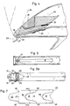
- Figure 1 is a side view of an improved ticket feeder operative to deliver individual tickets from a flexible strip of tickets wound in the form of a roll;
- Fig 2 is a side view of the inventive ticket feeder, partly in section;
- Fig 3 is a view of the ticket feeder of Fig 2 from above, but with the slide omitted;
- Fig 4 is a sectional view of the outfeed part of the inventive ticket feeder;
- Fig 5 is view from beneath of one of the pivotal cover parts of the ticket feeder;
- Fig 5a is a front view which includes part of the ticket-strip outfeed part of the ticket feeder;
- Fig 6 is a central sectional view on a larger scale of the outfeed part of said feeder with the displaceable slide shown in an active and in a passive position; and
- Fig 7 illustrates a roll of mutually connected tickets intended for use in the ticket feeder of the inventive assembly.
- Shown in Fig 1 is a
ticket feeder 10 which accommodates in roll form a flexible and continuous strip of tickets and which functions to separate the tickets one from the other when the strip is pulled manually. The ticket feeder includes acasing 11 and anattachment part 12 which is connected firmly to the casing and by means of which the ticket feeder can be removeably attached to an appropriate wall attachment (not shown). - The
attachment part 12, which is shown partly in section in Fig 2 and from above in Fig 3, is detachably connected to vertically spaced and rearwardly projectinglugs 13, each of which has apivot pin 14. Theticket feeder 10 can therewith pivot on thepin 14 and theattachment part 12 hasvertical surfaces stiff spring 17 mounted horizontally within theattachment part 12 funtions to return theticket feeder 10 to the position shown in Fig 3, in which thefeeder 10 and theattachment part 12 lie essentially in one and the same horizontal plane, subsequent to pivoting said ticket feeder. - In the case of the illustrated embodiment, the
casing 11 of theticket feeder 10 comprises a first,upper cover part 18 which is pivotally mounted on apivot connection 19 described in more detail herebelow. The purpose of the upwardlypivotable cover part 18 is to enable the upper part of theticket feeder 10 to be exposed so that a ticket roll 20 (Fig 1) can be introduced into thecasing 11, saidroll 20 normally comprising 4000-5000 tickets in continuous strip form wound on a bobbin, such as to form said ticket roll. - The
reference numeral 11b in Fig 2 identifies an internal limiting wall which is positioned so that if the ticket roll should begin to rotate when the free flap on the continuous ticket strip is pulled, the continuous strip would also unwind from the roll. This unwinding of the strip from the roll is limited and controlled by thewall part 11b in a manner such that any lengths of strip that might unwind from the roll will take an S-shape, which would not disturb normal use of the assembly. - For practical reasons, the improved
ticket feeder 10 is provided with a second,lower cover part 21 on the same side of the casing as thefirst cover part 18. Thissecond cover part 21 can be swung downwards about a lower hinge means 22. When theupper cover part 18 is swung upwards and thelower cover part 21 is swung downwards, the whole of one side of thecasing 11 will be opened, so that anew ticket roll 20 can be inserted into the ticket feeder, with the bobbin on which the ticket strip is wound resting onflanges 23′located on mutually opposite casing sides inwardly of the openings, whereby the side edges of theticket roll 20 will be slightly spaced from the side walls of thecasing 11. The other, mutually opposing sides of thecasing 11, on the other hand, form an integral part of the casing. Arranged at the top of thecasing 11 of the illustrated ticket feeder, and to the left in Figures 1 and 2, is a ticket-strip outfeed part, which will now be described. - In the ticket-outfeed region of the ticket feeder, the undivided side of the
casing 11 has an elongated ticket path which extends substantially in the direction in which the strip is pulled and the end of which located nearest theroll 20 is curved or gently rounded. The centre of theroll 20 preferably lies in the same, or approxamatly the same plane as the free end of the ticket feed path. The ticket-feed path presents a horizontal, firstsmooth feed surface 24 which merges with a second feed surface 26 (Fig 6) which slopes downwardly towards theoutfeed aperture 25 and which is terminated with afirst lip 27, said lip being slightly curved in the case of the illustrated embodiment. The slopingsurface 26 of the feed path is located essentially in the extension of an optimum ticket-strip pulling direction, and the actual outfeedaperture 25 is located on a lower plane than the lowest point of thesloping feed surface 26, the horizontal, upper surface of thelip 27 forming a support for a part of the flap on the free end or outermost end of the ticket strip. Provided on that part of thepath surface 26 located adjacent thelip 27 is abead 28 which extends across theguide surface 26. Thebead 28 resembles the end of a ski-jump construction, i.e. thebead 28 extends slightly upwards at its junction with theguide surface 26 and then drops almost vertically downwards to join thelip 27. The width extension of thebead 28 corresponds approximately to the width A (Fig 7) of a ticket. Extending on respective sides of thebead 28 aresurfaces 29 which lie in substantially the same plane as thebottom surface 26 of the feed path and which merge with thelip 27. Thebottom guide surface surface 26 of the feed path is provided along one edge region thereof with atransparent window 30, the function of which is described herebelow (Fig 3). - The aforedescribed outfeed part of the ticket feeder constitutes means for guiding and feeding the continuous ticket strip taken off the
roll 20. - The
ticket feed path wall parts 31, of which one is removably attached. In the region of the ticket outfeedaperture 25,respective wall parts 31 are provided with an outwardly extending pin 32 (e.g. Fig 3) which forms theaforesaid pivot attachment 19 for theupper cover part 18. Each ofsaid wall parts 31 is also provided with agroove 33 which extends in the longitudinal direction of the feed path and widens towards theoutfeed aperture 25. Thegrooves 33 are spaced from the upper edge surface ofrespective walls 31 and function as guide means for the sides of anelongated slide 34 which is mounted for limited movement in the longitudinal direction of the ticket strip. - The under
surface 35 of theslide 34 functions as second guide means for the ticket strip, said strip being intended to be fed between the mutually opposingguide surfaces guide surface 35 of theslide 34 merges with a downwardly and rearwardly extendingsecond lip 37 in the region of the ticket outfeed aperture. The end or tip of thelip 37 is rounded and is localised at a small distance from the upwardly facing surface of the outfeed orguide lip 27 on thecasing 11, such as to form a slot through which the ticket strip is fed. The bottom surface of theslide 34, which forms thetop guide surface 35 of the feed path, is also configured so that the feed path widens in a direction towards the outfeed 25 of the ticket feeder to form a larger gap 36 (Fig 4), although solely within the approximate region of thebead 28 on theguide surface 26. The aforementioned edge-margin surfaces 29 are not included in the gap widening. As will be seen from Figures 4 and 6 for instance, a relatively wide gap is formed between the upper end of thebead 28 and the region in which theguide surface 35 on theslide 34 changes direction and merges with thelip 37, which in the ticket-feeding state of theticket feeder 10 terminates immediately beneath the side of thebead 28 which faces theoutfeed aperture 25. - The upper part of the
slide 34 is configured with an upwardlyopen recess 38 and with a rearward,inclined wall 38a. - As illustrated in Fig 4, the
ticket feeder 10 includes apull spring 39 which is attached at one end to apin 40 in theslide 34 and at the other end to a pin in thewall part 31 located on the same side. A corresponding arrangement is found on the opposite side. - Fig 5 is a view of the inside of the
cover part 18. As shown in the Figure, the cover part includes amember 41 which is complementary in shape to the shape of therecess 38 in theslide 34. Consequently, when a raised cover part (fig 4) is lowered, themember 41 will engage therecess 38 and force theslide 34 to move rearwards against the action of thespring 39, to the position shown in Fig 4. When thecover part 18 is again raised, theslide 34 is moved forwards by thespring 39 to a passive position (fig 6) in which, for instance, a new ticket roll can be inserted into the feeder (after lowering the cover part 21) and brought between and into coaction with the guide surfaces 26 and 35 of the feed path. Theslide 34 can be removed, by dismantling theremovable wall part 31. - Mounted on the underside of the
bottom guide surface 26 of the ticket feed path are mutually spacedattachment parts 42 between which adetector device 43 is attached. Thedetector device 43 is positioned beneath thetransparent part 30 in the bottomticket guide surface 26 and can, in one embodiment, comprises a circuit card comprising an IR diode and a reciever. An electrical conductor (not shown) connects the detector device with a microprocessor provided with an internal and/or external display which informs personnel of, for instance, the number of people queuing for service, thereby enabling additional service personnel to be called upon if necessary. The display can also be made to show the expected waiting time. Other internal and/or external information functions are possible, of course. - Each individual ticket in the continuous ticket strip has a colour marking provided on its undersurface and on one edge margin thereof, this colour marking being readable by the detector. Furthermore, each fifth ticket, for instance, may be provided with a colour marking which differs from the colour marking of the four immediately preceding or the four immediately following markings. The arrangement may be such as to detect the first mentioned colour marking and to send a corresponding signal, for instance, to a counter, so as to provide internal information of the number of customers served and information concerning the number of queuing customers, so that additional service personnel can be called upon when necessary. Such a detection arrangement can also function to indicate to a customer the expected waiting time before he/she is attended to. Other internal/external information can also be given, depending upon the sophistication of the electronic equipment used. The continuous ticket strip in roll form used in conjunction with the aforedescribed ticket feeder is comparable with the ticket strip illustrated and described in the aforesaid US-A-4,047,652.
- Fig 7 illustrates a part of the continuous ticket strip, which is assumed to have been unwound from the
ticket roll 20. This continuous strip of tickets has punched therealong in mutually uniform relationship and in a known manner a number ofpenetrating lines 44a, 44b such as to form tongue-shapedflaps 45 and correspondingly configuredflap openings 46. It will be understood that theflaps 45 and theflap openings 46 can be given a configuration different to that shown, depending, among other things, on the width of the ticket strip. Distinct from the ticket strip according to US-A-4,047,652, none of theinventive flaps 45 is fully formed, since the centre of the ultimate flap is connected with the ultimate flap opening 46 by asmall bridge 50, as shown in fig 7. - As will be understood, when separated from the strip each individual ticket will present at its forward end a tongue-shaped
flap 45, which may have any desired configuration, whereas the rear end of the ticket will present a recess corresponding to and accommodating the flap of the immediatly following ticket and thus forming aflap opening 46. In the case of the illustrated emodiment, the tongue-shaped flap of each individual ticket is connected to the continuous strip along thegreatest width 47 of theflap 45. This connectingpart 47 of each flap extends preferably at right angles to the longitudinal axis of the strip and terminates short of mutually opposite side edges, to formshoulders shoulders flap 45 at its base, the broader theshoulders shoulders - When the
ticket feeder 10 is in its working state, it is assumed that aticket roll 20 is mounted in the feeder in the manner illustrated in Fig 2. The continuous ticket strip indicated in Fig 2 - is passed over a rounded end of the feed path surface 24 and into thegap 36, defined between the guide surfaces 26 and 35 of said path (Fig 4). In a functional position, a ticket flap ortongue 45 will protrude beyond theoutfeed aperture 25 of thefeeder 10, ready to be gripped and pulled. It will be seen that thebridge piece 50 between anultimate flap 45 and an ultimate flap opening 46 will prevent the flap from jutting from the plane of the strip, thereby enabling the continuous ticket strip to be guided and fed in a smooth path without hinderance of flaps which protrude from the plane of the strip (US-A-4,047,652). - When the
flap 45 is subjected to a pulling force in the direction of the arrow (A Fig 6), so as to remove the outermost ticket from the continuous ticket strip, two conditions must be fulfilled, namely that thebridge piece 50 is broken in a first phase of the pulling action and that theshoulders ticket flap 45 of a rearwardly located strip part slides over thebead 28, this flap will be located on a higher level than the ticket being torn from the strip. This rearwardly located flap will attempt to continue to move in the direction enforced by thebead 28, while the remainder of the strip tends to continue in the pulling direction (arrow A and Fig 6). It will be seen that since the flap of the rearwardly lying ticket runs over thebead 28 and the remainder of the ticket extends along thesurfaces 29 on opposite sides of thebead 28 in thefeed path bridge piece 50 connecting the centre of the immediately following ticket with the flap opening of the outermost ticket (see Fig 7) to rupture and therewith separate the outermost ticket from the immediately following ticket. The forward end of the flap thus released will, in this stage, be located immediately outside theoutfeed aperture 25 of thefeeder 10, and the flap will strive to move upwards towards the widened space approximatly at the point X in Fig 6 while the rearward part of the flap will be "folded" slightly, which causes a very short interruption in the forward movement of the ticket strip. The pulling action will now be transferred to theshoulders - The described ticket feeder operative to deliver individual tickets from a continuous ticket strip affords the important advantage that the free ticket-tongue protruding from the
outfeed aperture 25 can, in practise, be pulled forwards at any conceivable angle without impairing the ticket dispensing function of thefeeder 10.
Claims (15)
- A ticket dispensing assembly comprising a ticket feeder (10) and a continuous, flexible ticket strip in roll form (20), said ticket feeder (10) including a casing (11) which accommodates the ticket roll (20), at least one cover part (18) pivotally connected to said casing (11), a feed path operative to guide a continuous strip length taken from the roll (20), such that the free end of the continuous ticket strip will project from the ticket feeder (10) through an outfeed aperture (25) and serve as a finger grip for outward feeding of the continuous strip in response to a pulling force exerted manually on said strip, wherein means are provided which in response to a pulling force on said free end of the strip cause the strip parts (48,49) which join two mutually adjacent tickets together to separate, and wherein the continuous ticket strip has punched therein at regular intervals there along parting lines (44a,44b) which form a plurality of tongue-shaped flaps (45) and flap-openings (46), and wherein those strip parts (48, 49) which join together two mutually adjacent tickets are located at the extremities of a punched parting line (44a,44b) and extend approximately transversely to the longitudinal axis of the ticket strip, characterized in that the feed path operative to guide the continuous ticket strip in said feeder (10) comprises two vertically spaced surfaces (26, 35) between which the continuous strip is guided; in that the bottom guide surface (26) merges with a first lip (27) which is located externally of the outfeed aperture of the feeder (10) and the upper surface of which lip is located on a lower plane than an imaginary extension of said bottom guide surface (26); in that said bottom guide surface (26) at the point of its junction with said first guide lip (27) presents an elongated bead (28) which extends across the feed path and terminates short of respective sides thereof; in that the end of said upper guide surface (35) adjacent the outfeed aperture projects beyond the bead (28) and is configured with a downwardly and rearwardly extending second lip (37), the tip of which terminates immediately beneath the side of the bead (28) that faces towards the outfeed aperture (25); and in that the upper guide surface (35) is configured with a depression (X) adjacent the base of said second lip (37), such that the feed path widens in a direction towards said outfeed aperture (25) to form a larger gap (36) between the upper and bottom guide surfaces (35, 26) within the approximate region of said bead (28), the edge margins of the bottom guide surface (26) to the sides of the bead (28) being not included in the gap widening.
- An assembly according to claim 1, characterized in that the upper guide surface (35) of the feed path is formed by the bottom surface of a slide (34) which is mounted for limited movement between the casing sides (31) of the ticket feeder (10).
- An assembly according to claim 2, characterized in that the mutually opposing sides (31) of said casing have provided therein elongated grooves (33) in which the slide (34) is guided.
- An assembly according to claim 2 or 3, characterized in that the slide (34) is biassed in one direction of movement by a spring (39).
- An assembly according to one or more claims 2 to 4 characterized in that the upwardly extending part of the slide (34) includes an upwardly open recess (38) which coacts with a correspondingly shaped element (41) located within a cover part (18) which is pivotally connected to the casing (11) of the ticket feeder (10).
- An assembly according to claim 1, characterized in that the bottom guide surface of the ticket guide path is rigidly connected to a wall part (31) of the casing and includes a first, straight surface (24) which merges with a sloping second surface (26); and in that the end of the guide path located adjacent the ticket roll has gently rounded surfaces for guiding the continuous ticket strip as it leaves the ticket roll.
- An assembly according to claim 6, characterized in that said end of the guide path adjacent the ticket roll lies approximately in the same vertical plane as the centre of the ticket roll (20).
- An assembly according to one or more of the preceding claims, characterized in that the ticket feeder (10) has an internal wall (11b) which extends vertically from the upper part of the casing (11) to approximately a level corresponding to the maximum diameter of a ticket roll (20).
- An assembly according to one or more of the preceding claims, characterized in that the bottom guide surface (24, 26) of said feed path has a transparent part (30); and in that mounted beneath said bottom guide surface is a detachable detector device (43) which is connected by electrical connectors to one or more display devices equipped with a microprocessor or microprocessors.
- An assembly according to claim 1, characterized in that one side of the casing (11) of the ticket feeder (10) is composed of cover parts (18, 22) which can be pivoted independently of one another and which afford access to the interior of the ticket feeder (10).
- An assembly according to one or more of the preceding claims, characterized in that the ticket roll (20) is wound on a bobbin which is intended to rest on flanges mounted internally on the sides of the casing.
- An assembly according to one or more of the preceding claims, characterized in that the ticket feeder (10) has a detachable attachment part (12) which is intended for detachable attachment of the ticket feeder to a wall attachment.
- An assembly according to claim 12, characterized in that the attachment part (12) is pivotally connected to the ticket feeder (10) in a manner to permit limited rotation of the ticket feeder (10), and a spring (17) is provided for aligning the ticket feeder with the attachment part.
- An assembly according to claim 1, characterized in that the flap opening (46) of one ticket of said continuous strip of tickets is connected to the flap (45) of an immediately following ticket by means of a thin bridge of material (50).
- An assembly according to claim 1 or claim 4, characterized in that the mutually opposite strip parts (48, 49) of said ticket strip which connect two mutually adjacent tickets together have a tear line which extends from respective punched lines in a direction towards the outer edges of the ticket strip.
Priority Applications (1)
| Application Number | Priority Date | Filing Date | Title |
|---|---|---|---|
| EP94105301A EP0621561B1 (en) | 1989-09-01 | 1990-08-16 | Ticket strip for a ticket dispenser |
Applications Claiming Priority (3)
| Application Number | Priority Date | Filing Date | Title |
|---|---|---|---|
| SE8902897A SE465099B (en) | 1989-09-01 | 1989-09-01 | DEVICE FOR SEPARATE SEPARATION OF TICKETS |
| SE8902897 | 1989-09-01 | ||
| PCT/SE1990/000530 WO1991003802A1 (en) | 1989-09-01 | 1990-08-16 | Ticket dispenser |
Related Child Applications (1)
| Application Number | Title | Priority Date | Filing Date |
|---|---|---|---|
| EP94105301.9 Division-Into | 1994-04-06 |
Publications (2)
| Publication Number | Publication Date |
|---|---|
| EP0489835A1 EP0489835A1 (en) | 1992-06-17 |
| EP0489835B1 true EP0489835B1 (en) | 1994-11-30 |
Family
ID=20376789
Family Applications (2)
| Application Number | Title | Priority Date | Filing Date |
|---|---|---|---|
| EP94105301A Expired - Lifetime EP0621561B1 (en) | 1989-09-01 | 1990-08-16 | Ticket strip for a ticket dispenser |
| EP90913563A Expired - Lifetime EP0489835B1 (en) | 1989-09-01 | 1990-08-16 | Ticket dispenser |
Family Applications Before (1)
| Application Number | Title | Priority Date | Filing Date |
|---|---|---|---|
| EP94105301A Expired - Lifetime EP0621561B1 (en) | 1989-09-01 | 1990-08-16 | Ticket strip for a ticket dispenser |
Country Status (13)
| Country | Link |
|---|---|
| US (2) | US5294034A (en) |
| EP (2) | EP0621561B1 (en) |
| AT (2) | ATE143741T1 (en) |
| AU (1) | AU634279B2 (en) |
| BR (1) | BR9007602A (en) |
| CA (1) | CA2064812C (en) |
| DD (1) | DD297725A5 (en) |
| DE (2) | DE69014641T2 (en) |
| DK (1) | DK0621561T3 (en) |
| ES (2) | ES2092349T3 (en) |
| RU (2) | RU2127698C1 (en) |
| SE (1) | SE465099B (en) |
| WO (1) | WO1991003802A1 (en) |
Families Citing this family (40)
| Publication number | Priority date | Publication date | Assignee | Title |
|---|---|---|---|---|
| FR2697931B1 (en) * | 1992-11-12 | 1995-02-03 | Sagem | Ticket outlet chute for ticket dispensing machine. |
| WO1997009694A1 (en) * | 1994-03-25 | 1997-03-13 | Esselte Meto International Gmbh | Tape roll |
| US5755369A (en) * | 1995-07-26 | 1998-05-26 | Holmes; Ronald J. | Raffle ticket dispenser |
| DE19613821A1 (en) * | 1996-04-09 | 1997-10-16 | Esselte Meto Int Gmbh | Device for dispensing labels |
| US6235369B1 (en) * | 1997-09-03 | 2001-05-22 | Velcro Industries B.V. | Strip-form fastening and dispensing |
| US6321965B1 (en) | 1999-05-04 | 2001-11-27 | Lavi Industries | Enhanced dispensing system for luggage tagging |
| US6910579B2 (en) | 2002-05-28 | 2005-06-28 | Georgia-Pacific Corporation | Refillable flexible sheet dispenser |
| US7014065B2 (en) * | 2004-02-11 | 2006-03-21 | Schafer Systems Inc. | Dispenser for series-connected tickets |
| US20070061868A1 (en) * | 2005-08-03 | 2007-03-15 | Aladdin Knowledge Systems Ltd. | One-time password client |
| FR2902696A1 (en) * | 2006-06-27 | 2007-12-28 | Ask Sa | NON-CONTACT CHIP TICKET ASSEMBLY |
| EP1929912A1 (en) * | 2006-12-06 | 2008-06-11 | The Procter and Gamble Company | Tissue roll with angled perforations |
| GB0717525D0 (en) | 2007-09-08 | 2007-10-17 | Catchpoint Ltd | Label separation and application apparatus and method |
| US20100006587A1 (en) * | 2008-07-09 | 2010-01-14 | Newmark Charles M | Beverage Label System and Dispenser |
| WO2010074632A1 (en) * | 2008-12-22 | 2010-07-01 | Q-Matic Ab | Detachable web |
| US20100264249A1 (en) * | 2009-04-20 | 2010-10-21 | Kranson Industries, Inc. D/B/A Tricorbraun | Soap tape dispenser |
| US8468938B2 (en) | 2010-06-21 | 2013-06-25 | The Procter & Gamble Company | Apparatus for perforating a web material |
| US8268429B2 (en) | 2010-06-21 | 2012-09-18 | The Procter & Gamble Company | Perforated web product |
| US8535483B2 (en) | 2010-06-21 | 2013-09-17 | The Procter & Gamble Company | Apparatus for uniquely perforating a web material |
| US8763526B2 (en) | 2010-06-21 | 2014-07-01 | The Procter & Gamble Company | Apparatus for perforating a web material |
| US8757058B2 (en) | 2010-06-21 | 2014-06-24 | The Procter & Gamble Company | Process for perforating a web |
| US8287977B2 (en) | 2010-06-21 | 2012-10-16 | The Procter & Gamble Company | Uniquely perforated web product |
| US8283013B2 (en) | 2010-06-21 | 2012-10-09 | The Procter & Gamble Company | Uniquely perforated web product |
| US8443725B2 (en) | 2010-06-21 | 2013-05-21 | The Procter & Gamble Company | Method of perforating a web |
| US8763523B2 (en) | 2010-06-21 | 2014-07-01 | The Procter & Gamble Company | Method of perforating a web material |
| US8287976B2 (en) | 2010-06-21 | 2012-10-16 | The Procter & Gamble Company | Uniquely perforated web product |
| US9259848B2 (en) | 2010-06-21 | 2016-02-16 | The Procter & Gamble Company | Method for providing a web with unique lines of weakness |
| WO2014201071A1 (en) | 2013-06-12 | 2014-12-18 | The Procter & Gamble Company | A perforating apparatus for manufacturing a nonlinear line of weakness |
| EP3007598A1 (en) | 2013-06-12 | 2016-04-20 | The Procter & Gamble Company | A nonlinear line of weakness formed by a perforating apparatus |
| US11254024B2 (en) | 2013-06-12 | 2022-02-22 | The Procter & Gamble Company | Method of perforating a nonlinear line of weakness |
| EP2835160A1 (en) * | 2013-08-09 | 2015-02-11 | Scientific Games International Limited | An array of interconnected lottery tickets |
| WO2016148900A1 (en) | 2015-03-17 | 2016-09-22 | The Procter & Gamble Company | Apparatus for perforating a nonlinear line of weakness |
| WO2016148899A1 (en) | 2015-03-17 | 2016-09-22 | The Procter & Gamble Company | Apparatus for perforating a web material |
| WO2016148894A1 (en) | 2015-03-17 | 2016-09-22 | The Procter & Gamble Company | Method for perforating a nonlinear line of weakness |
| US11021339B2 (en) * | 2017-05-22 | 2021-06-01 | Bedford Industries, Inc. | Elastic band dispenser |
| US11806890B2 (en) | 2017-09-11 | 2023-11-07 | The Procter & Gamble Company | Perforating apparatus and method for manufacturing a shaped line of weakness |
| US11806889B2 (en) | 2017-09-11 | 2023-11-07 | The Procter & Gamble Company | Perforating apparatus and method for manufacturing a shaped line of weakness |
| WO2019051462A1 (en) | 2017-09-11 | 2019-03-14 | The Procter & Gamble Company | Sanitary tissue product with a shaped line of weakness |
| US10974890B1 (en) * | 2020-03-26 | 2021-04-13 | Colhurst Covers, LLC | Container cover, dispenser and method of use |
| BR102020019640A2 (en) * | 2020-09-25 | 2022-04-12 | Adhespack Industria, Comércio, Importação E Exportação Ltda | Device for dispensing samples |
| US20240166463A1 (en) * | 2022-11-18 | 2024-05-23 | Adhespack Industria, Comércio, Importação e Exportação LTDA. | Sample activator and dispenser device |
Family Cites Families (20)
| Publication number | Priority date | Publication date | Assignee | Title |
|---|---|---|---|---|
| US405412A (en) * | 1889-06-18 | Perforated paper | ||
| US714652A (en) * | 1902-05-27 | 1902-11-25 | Wilbur M Davis | Toilet-paper. |
| US843579A (en) * | 1906-12-21 | 1907-02-12 | Guy W Burr | Means for holding and detaching ribbon-strip labels. |
| GB191206065A (en) * | 1912-03-11 | 1913-03-11 | Arnold James Tanner | An Improved Means for Issuing Tickets. |
| US1170589A (en) * | 1914-08-12 | 1916-02-08 | Seth Wheeler | Paper-roll. |
| US1704044A (en) * | 1927-05-06 | 1929-03-05 | Alonzo P Ingram | Dispensing and severing device for rolled strip material |
| US2023829A (en) * | 1935-02-14 | 1935-12-10 | Lester P Wright | Admittance strip ticket |
| US3467250A (en) * | 1968-01-25 | 1969-09-16 | Anthony N D Elia | Easy tear tape with lift tab |
| US4274661A (en) * | 1971-06-23 | 1981-06-23 | Monarch Marking Systems, Inc. | Composite web of pressure sensitive labels |
| US4047652A (en) * | 1972-01-26 | 1977-09-13 | Ake Ehrlund | Ticket dispensing assembly for dispensing tickets from a flexible strip |
| BE794624A (en) * | 1972-01-26 | 1973-05-16 | Turn O Matic Ab | DEVICE FOR REMOVING FROM A FLEXIBLE BAND PARTS OF A DETERMINED LANGUAGE |
| US4210688A (en) * | 1977-03-28 | 1980-07-01 | Kabushiki Kaisha Sato | Pressure sensitive label strip for use in a label printing machine |
| US4244502A (en) * | 1978-09-15 | 1981-01-13 | Sven Iveter | Dispenser for roll of flexible strip |
| SE413119B (en) * | 1978-10-04 | 1980-04-14 | Meto Marking Ab | DEVICE TO REMOVE A RUBBER OF MATERIAL MATERIALS, SUCH AS A RIBBLE OF COLLAPPERS, SEPARATELY SEPARATELY EQUIPMENT STRAP LENGTHS |
| NL173794B (en) * | 1980-01-16 | 1983-10-03 | Rollex Handel Bv | COMPOSITION OF A DEVICE FOR ISSUING TRACKING NUMBERS AND A RANGE OF CUSTOMIZED PAPER ON WHICH THESE TRACKING NUMBERS ARE APPLIED IN LENGTH. |
| US4320158A (en) * | 1980-05-30 | 1982-03-16 | Monarch Marking Systems, Inc. | Composite label web roll |
| US4364501A (en) * | 1980-12-15 | 1982-12-21 | Instrumental Products | Dispenser for roll of tickets in strip form |
| SE425442B (en) * | 1981-07-20 | 1982-09-27 | Per Martin Pettersson | PROCEDURE FOR EXPEDIATING CUSTOMERS IN A MULTIPLE CASH AND A PROCEDURE FOR IMPLEMENTING THE PROCEDURE |
| DE3605351C1 (en) * | 1986-02-20 | 1987-09-17 | Rupp Josef Peter | Device for dispensing strip sections |
| US5170957A (en) * | 1991-09-03 | 1992-12-15 | Len Carpenter | Dispenser of plastic bags with handles |
-
1989
- 1989-09-01 SE SE8902897A patent/SE465099B/en not_active IP Right Cessation
-
1990
- 1990-08-16 ES ES94105301T patent/ES2092349T3/en not_active Expired - Lifetime
- 1990-08-16 CA CA002064812A patent/CA2064812C/en not_active Expired - Fee Related
- 1990-08-16 EP EP94105301A patent/EP0621561B1/en not_active Expired - Lifetime
- 1990-08-16 DE DE69014641T patent/DE69014641T2/en not_active Expired - Fee Related
- 1990-08-16 RU RU94042404A patent/RU2127698C1/en not_active IP Right Cessation
- 1990-08-16 DK DK94105301.9T patent/DK0621561T3/en active
- 1990-08-16 RU SU5011679/28A patent/RU2072557C1/en not_active IP Right Cessation
- 1990-08-16 AT AT94105301T patent/ATE143741T1/en not_active IP Right Cessation
- 1990-08-16 AU AU63487/90A patent/AU634279B2/en not_active Ceased
- 1990-08-16 DE DE69028789T patent/DE69028789T2/en not_active Expired - Fee Related
- 1990-08-16 BR BR909007602A patent/BR9007602A/en not_active IP Right Cessation
- 1990-08-16 AT AT90913563T patent/ATE114841T1/en not_active IP Right Cessation
- 1990-08-16 US US07/828,938 patent/US5294034A/en not_active Expired - Fee Related
- 1990-08-16 EP EP90913563A patent/EP0489835B1/en not_active Expired - Lifetime
- 1990-08-16 WO PCT/SE1990/000530 patent/WO1991003802A1/en not_active Ceased
- 1990-08-16 ES ES90913563T patent/ES2064761T3/en not_active Expired - Lifetime
- 1990-09-03 DD DD90343790A patent/DD297725A5/en unknown
-
1994
- 1994-04-15 US US08/228,190 patent/US5453311A/en not_active Expired - Lifetime
Also Published As
| Publication number | Publication date |
|---|---|
| DE69028789D1 (en) | 1996-11-07 |
| CA2064812C (en) | 1999-02-02 |
| ES2064761T3 (en) | 1995-02-01 |
| CA2064812A1 (en) | 1991-03-02 |
| RU2072557C1 (en) | 1997-01-27 |
| DE69014641D1 (en) | 1995-01-12 |
| DE69028789T2 (en) | 1997-02-13 |
| DE69014641T2 (en) | 1995-04-13 |
| RU2127698C1 (en) | 1999-03-20 |
| BR9007602A (en) | 1992-06-30 |
| DD297725A5 (en) | 1992-01-16 |
| SE465099B (en) | 1991-07-22 |
| AU6348790A (en) | 1991-04-08 |
| SE8902897D0 (en) | 1989-09-01 |
| EP0621561A3 (en) | 1994-11-23 |
| ES2092349T3 (en) | 1996-11-16 |
| ATE114841T1 (en) | 1994-12-15 |
| WO1991003802A1 (en) | 1991-03-21 |
| DK0621561T3 (en) | 1997-03-17 |
| US5453311A (en) | 1995-09-26 |
| SE8902897L (en) | 1991-03-02 |
| US5294034A (en) | 1994-03-15 |
| EP0621561A2 (en) | 1994-10-26 |
| AU634279B2 (en) | 1993-02-18 |
| ATE143741T1 (en) | 1996-10-15 |
| EP0621561B1 (en) | 1996-10-02 |
| EP0489835A1 (en) | 1992-06-17 |
Similar Documents
| Publication | Publication Date | Title |
|---|---|---|
| US5294034A (en) | Ticket dispenser | |
| EP0605076B1 (en) | Perforated paper towel dispenser | |
| US4204618A (en) | Dispenser for roll of ticket tapes and the like | |
| CA2218427C (en) | Center pull sheet dispensing apparatus | |
| US4883197A (en) | Sample strip and dispensing apparatus therefor | |
| US6826991B1 (en) | Web transfer mechanism for flexible sheet dispenser | |
| JP4576120B2 (en) | Dispenser for sheet material | |
| US5762286A (en) | Dispenser for a plurality of center pull towels incorporating towel transfer mechanism | |
| US20010019070A1 (en) | Garment hanger having a removable size indicator | |
| CA2007099C (en) | Tear-edge guard | |
| US5549218A (en) | Paper towel dispenser | |
| US5954226A (en) | Envelope dispensing apparatus for an ATM | |
| GB2120639A (en) | Dispenser for web material | |
| US4244502A (en) | Dispenser for roll of flexible strip | |
| US4811545A (en) | Tag dispensing apparatus | |
| US20060177618A1 (en) | Tape and tape cassette containing the tape | |
| JP3698184B2 (en) | Paper cutting device | |
| KR20050103426A (en) | Tissue guide apparatus | |
| JPS6110997Y2 (en) | ||
| SE427345B (en) | Stamping device for strip labels |
Legal Events
| Date | Code | Title | Description |
|---|---|---|---|
| PUAI | Public reference made under article 153(3) epc to a published international application that has entered the european phase |
Free format text: ORIGINAL CODE: 0009012 |
|
| 17P | Request for examination filed |
Effective date: 19920323 |
|
| AK | Designated contracting states |
Kind code of ref document: A1 Designated state(s): AT BE CH DE DK ES FR GB IT LI LU NL SE |
|
| RAP1 | Party data changed (applicant data changed or rights of an application transferred) |
Owner name: ESSELTE METO INTERNATIONAL GMBH |
|
| 17Q | First examination report despatched |
Effective date: 19930923 |
|
| GRAA | (expected) grant |
Free format text: ORIGINAL CODE: 0009210 |
|
| AK | Designated contracting states |
Kind code of ref document: B1 Designated state(s): AT BE CH DE DK ES FR GB IT LI LU NL SE |
|
| PG25 | Lapsed in a contracting state [announced via postgrant information from national office to epo] |
Ref country code: IT Free format text: LAPSE BECAUSE OF FAILURE TO SUBMIT A TRANSLATION OF THE DESCRIPTION OR TO PAY THE FEE WITHIN THE PRE;WARNING: LAPSES OF ITALIAN PATENTS WITH EFFECTIVE DATE BEFORE 2007 MAY HAVE OCCURRED AT ANY TIME BEFORE 2007. THE CORRECT EFFECTIVE DATE MAY BE DIFFERENT FROM THE ONE RECORDED.SCRIBED TIME-LIMIT Effective date: 19941130 Ref country code: AT Effective date: 19941130 Ref country code: BE Effective date: 19941130 Ref country code: CH Effective date: 19941130 Ref country code: LI Effective date: 19941130 Ref country code: DK Effective date: 19941130 Ref country code: NL Effective date: 19941130 |
|
| REF | Corresponds to: |
Ref document number: 114841 Country of ref document: AT Date of ref document: 19941215 Kind code of ref document: T |
|
| REF | Corresponds to: |
Ref document number: 69014641 Country of ref document: DE Date of ref document: 19950112 |
|
| REG | Reference to a national code |
Ref country code: ES Ref legal event code: FG2A Ref document number: 2064761 Country of ref document: ES Kind code of ref document: T3 |
|
| ET | Fr: translation filed | ||
| REG | Reference to a national code |
Ref country code: CH Ref legal event code: PL |
|
| NLV1 | Nl: lapsed or annulled due to failure to fulfill the requirements of art. 29p and 29m of the patents act | ||
| PG25 | Lapsed in a contracting state [announced via postgrant information from national office to epo] |
Ref country code: GB Effective date: 19950816 |
|
| PG25 | Lapsed in a contracting state [announced via postgrant information from national office to epo] |
Ref country code: LU Free format text: LAPSE BECAUSE OF NON-PAYMENT OF DUE FEES Effective date: 19950831 |
|
| PLBE | No opposition filed within time limit |
Free format text: ORIGINAL CODE: 0009261 |
|
| STAA | Information on the status of an ep patent application or granted ep patent |
Free format text: STATUS: NO OPPOSITION FILED WITHIN TIME LIMIT |
|
| 26N | No opposition filed | ||
| GBPC | Gb: european patent ceased through non-payment of renewal fee |
Effective date: 19950816 |
|
| PGFP | Annual fee paid to national office [announced via postgrant information from national office to epo] |
Ref country code: SE Payment date: 20020806 Year of fee payment: 13 |
|
| PGFP | Annual fee paid to national office [announced via postgrant information from national office to epo] |
Ref country code: FR Payment date: 20020808 Year of fee payment: 13 |
|
| PGFP | Annual fee paid to national office [announced via postgrant information from national office to epo] |
Ref country code: ES Payment date: 20020826 Year of fee payment: 13 |
|
| PG25 | Lapsed in a contracting state [announced via postgrant information from national office to epo] |
Ref country code: SE Free format text: LAPSE BECAUSE OF NON-PAYMENT OF DUE FEES Effective date: 20030817 |
|
| PG25 | Lapsed in a contracting state [announced via postgrant information from national office to epo] |
Ref country code: ES Free format text: LAPSE BECAUSE OF NON-PAYMENT OF DUE FEES Effective date: 20030818 |
|
| PGFP | Annual fee paid to national office [announced via postgrant information from national office to epo] |
Ref country code: DE Payment date: 20030828 Year of fee payment: 14 |
|
| EUG | Se: european patent has lapsed | ||
| PG25 | Lapsed in a contracting state [announced via postgrant information from national office to epo] |
Ref country code: FR Free format text: LAPSE BECAUSE OF NON-PAYMENT OF DUE FEES Effective date: 20040430 |
|
| REG | Reference to a national code |
Ref country code: FR Ref legal event code: ST |
|
| REG | Reference to a national code |
Ref country code: ES Ref legal event code: FD2A Effective date: 20030818 |
|
| PG25 | Lapsed in a contracting state [announced via postgrant information from national office to epo] |
Ref country code: DE Free format text: LAPSE BECAUSE OF NON-PAYMENT OF DUE FEES Effective date: 20050301 |