EP0489820B1 - Pulsatory burner - Google Patents
Pulsatory burner Download PDFInfo
- Publication number
- EP0489820B1 EP0489820B1 EP90913344A EP90913344A EP0489820B1 EP 0489820 B1 EP0489820 B1 EP 0489820B1 EP 90913344 A EP90913344 A EP 90913344A EP 90913344 A EP90913344 A EP 90913344A EP 0489820 B1 EP0489820 B1 EP 0489820B1
- Authority
- EP
- European Patent Office
- Prior art keywords
- combustion chamber
- air inlet
- neck
- valve
- seat
- Prior art date
- Legal status (The legal status is an assumption and is not a legal conclusion. Google has not performed a legal analysis and makes no representation as to the accuracy of the status listed.)
- Expired - Lifetime
Links
- 238000002485 combustion reaction Methods 0.000 claims abstract description 58
- XLYOFNOQVPJJNP-UHFFFAOYSA-N water Substances O XLYOFNOQVPJJNP-UHFFFAOYSA-N 0.000 claims abstract description 22
- 238000001816 cooling Methods 0.000 claims abstract description 3
- 239000000446 fuel Substances 0.000 claims description 8
- 238000002347 injection Methods 0.000 description 8
- 239000007924 injection Substances 0.000 description 8
- 239000003921 oil Substances 0.000 description 8
- 239000007789 gas Substances 0.000 description 7
- 239000000571 coke Substances 0.000 description 4
- 238000007789 sealing Methods 0.000 description 4
- 230000015572 biosynthetic process Effects 0.000 description 3
- 238000011109 contamination Methods 0.000 description 3
- UGFAIRIUMAVXCW-UHFFFAOYSA-N Carbon monoxide Chemical compound [O+]#[C-] UGFAIRIUMAVXCW-UHFFFAOYSA-N 0.000 description 2
- 230000002349 favourable effect Effects 0.000 description 2
- 238000010304 firing Methods 0.000 description 2
- 239000003546 flue gas Substances 0.000 description 2
- 239000003779 heat-resistant material Substances 0.000 description 2
- 230000005855 radiation Effects 0.000 description 2
- 229910001018 Cast iron Inorganic materials 0.000 description 1
- 206010061307 Neck deformity Diseases 0.000 description 1
- 230000004323 axial length Effects 0.000 description 1
- 238000005452 bending Methods 0.000 description 1
- 239000002131 composite material Substances 0.000 description 1
- 238000010276 construction Methods 0.000 description 1
- 230000003247 decreasing effect Effects 0.000 description 1
- 239000000428 dust Substances 0.000 description 1
- 239000012530 fluid Substances 0.000 description 1
- 239000000295 fuel oil Substances 0.000 description 1
- 239000012212 insulator Substances 0.000 description 1
- 239000007788 liquid Substances 0.000 description 1
- 239000002184 metal Substances 0.000 description 1
- 229910052751 metal Inorganic materials 0.000 description 1
- 238000000034 method Methods 0.000 description 1
- 239000000203 mixture Substances 0.000 description 1
- 238000012544 monitoring process Methods 0.000 description 1
- 238000005457 optimization Methods 0.000 description 1
- 239000004033 plastic Substances 0.000 description 1
- 230000000284 resting effect Effects 0.000 description 1
- 239000004071 soot Substances 0.000 description 1
- 238000009834 vaporization Methods 0.000 description 1
- 230000008016 vaporization Effects 0.000 description 1
Images

Classifications
-
- F—MECHANICAL ENGINEERING; LIGHTING; HEATING; WEAPONS; BLASTING
- F23—COMBUSTION APPARATUS; COMBUSTION PROCESSES
- F23C—METHODS OR APPARATUS FOR COMBUSTION USING FLUID FUEL OR SOLID FUEL SUSPENDED IN A CARRIER GAS OR AIR
- F23C15/00—Apparatus in which combustion takes place in pulses influenced by acoustic resonance in a gas mass
-
- F—MECHANICAL ENGINEERING; LIGHTING; HEATING; WEAPONS; BLASTING
- F24—HEATING; RANGES; VENTILATING
- F24H—FLUID HEATERS, e.g. WATER OR AIR HEATERS, HAVING HEAT-GENERATING MEANS, e.g. HEAT PUMPS, IN GENERAL
- F24H9/00—Details
- F24H9/18—Arrangement or mounting of grates or heating means
- F24H9/1809—Arrangement or mounting of grates or heating means for water heaters
- F24H9/1832—Arrangement or mounting of combustion heating means, e.g. grates or burners
- F24H9/1836—Arrangement or mounting of combustion heating means, e.g. grates or burners using fluid fuel
-
- F—MECHANICAL ENGINEERING; LIGHTING; HEATING; WEAPONS; BLASTING
- F23—COMBUSTION APPARATUS; COMBUSTION PROCESSES
- F23C—METHODS OR APPARATUS FOR COMBUSTION USING FLUID FUEL OR SOLID FUEL SUSPENDED IN A CARRIER GAS OR AIR
- F23C2900/00—Special features of, or arrangements for combustion apparatus using fluid fuels or solid fuels suspended in air; Combustion processes therefor
- F23C2900/03008—Spherical or bulb-shaped combustion chambers
Definitions
- the invention relates to a boiler containing a pulsatory burner which is mounted in the water space of a hot water boiler and comprises a combustion chamber with a neck provided as an air inlet, and a nonreturn valve controlling the air flow through the air inlet to the combustion chamber, said nonreturn valve having a seat concentric with the air inlet, wherein there is provided at least one air inlet opening, and a flat, relatively thin circular valve ring which is elastically flexible and, in the closed position of the valve, engages the seat and keeps the air inlet opening closed but can be operated to an open position by depression in the combustion chamber.
- DE-C-933 651 discloses a boiler comprising a pulsatory burner consisting of a combustion chamber with a neck provided as an air inlet and a nonreturn valve controlling the air flow through the air inlet to the combusion chamber.
- SE-B-435 098 shows how the nonreturn valve can be constructed and how the air inlet can be provided in a pulsatory burner of the above-mentioned type.
- the valve seat then consists of a flared portion at one end of the neck, the other end thereof being connected to the combustion chamber.
- the neck bears a valve body in which the seat and the valve ring are provided, and in the neck a fuel injection nozzle having ignition electrodes is provided. It is noted that the neck has a considerable axial length, and the reason therefor is that the nonreturn valve shall be spaced from the combustion chamber to avoid contamination and formation of coke on the valve seat.
- the injection nozzle will be at a relatively large distance from the combustion chamber, which is favourable since as a consequence thereof it will be subjected to contamination and exposed to heat radiation from the combustion chamber to a smaller extent but, on the other hand, due to such a location of the nozzle a bad fuel distribution in the combustion chamber will be obtained.
- the air inlet represents a dead volume in the combustion chamber, i.e. a volume which is not necessary for the combustion proper.
- the dead volume being large, the movement of the valve ring will not occur as quickly and distinctly as desired.
- the opening period for the nonreturn valve becomes relatively long, and when the nonreturn valve is open back flow of gas from the combustion chamber can occur through the air inlet, dust (soot) being transported up to the valve seat and the valve disk causing contamination thereon.
- the nonreturn valve does not work distinctly, the function of the burner becomes unreliable.
- the purpose of the invention is to eliminate or at least considerably reduce the said disadvantages by reducing the dead volume of the combustion chamber and locating the nonreturn valve closer to the combustion chamber.
- the pulsatory burner of the above-mentioned type for this purpose has obtained the characterizing features of claim 1.
- FIG 1 a hot water boiler 10 with a water space 12 formed by a tank 11 is fragmentarily shown, a pulsatory burner 13 being provided in the water space.
- the pulsatory burner comprises a spherical combustion chamber 14 having an opening 15 which is connected to a flue gas outlet by a conduit 16, said flue gas outlet forming a Helmholz-resonator together with the combustion chamber, and further having a cylindrical neck 17 provided on the top thereof, which is attached to the wall 11 and supports a nonreturn valve 18.
- This valve comprises a valve body which consists of a lower part 19 and a cover 20 which are detachably connected by means of bolt joints.
- the lower part is inserted into the neck 17 at a cylindrical socket 21, sealing O-rings 22 being provided between the socket and the neck, and the lower part being attached to the neck 17 by means of a snap-in lock 23 which engages outwardly projecting flanges 24 and 25 on the lower part and on the neck, respectively.
- the lower part forms a circular valve seat 26 which joins the socket 21 at a curved interior surface portion 27 which joins the cylindrical interior surface of the neck 17.
- a relatively thin, circular valve ring 29 which has to be elastically flexible and can consist of metal, or plastic, or some composite material.
- the openings 28 are distributed along a circle, and on both sides of the openings elastic O-rings 30 and 31 are provided which are received in annular grooves in the seat.
- an O-ring 32 is also provided which is received in an annular groove in the seat, and the outer edge of the valve ring is received between the cover 20 and this latter O-ring.
- the cover forms a centrally projecting cylindrical portion on the upper side thereof with a downwards open central threaded bottom hole 34 into which an injection nozzle 35 is screwed, and to the bottom hole 34 a threaded cross bore 36 connects for the connection of a conduit 37 for supply of fuel oil (FIG 1).
- the injection nozzle extends centrally into the socket 21 and opens into a constriction in the passage through the socket, formed by the surface 27, which forms a kind of a venturi nozzle.
- the cover 20 has on the lower side thereof a ring shaped recess which is bounded by a curved surface 38 the shape of which is adapted to the shape of the curved surface 27 so that, around the injection nozzle 35, there is a ring shaped passage which extends from the air inlet openings 28 down into the neck 17 which forms the air inlet to the combustion chamber.
- the neck is surrounded on the outside thereof by a downwards open cover 40 which is connected to a conduit 41 provided along the wall 11, a tube 42 for output hot water from the boiler being connected to said conduit.
- the water which is heated in the water space 12 of the boiler by means of the pulsatory burner is thus forced to pass into the radiator system through the tube 42 in contact with the outside of the neck 17 inside the cover 40 in order that this water will cool the neck, which is made relatively short as disclosed in FIG 1.
- a socket 43 Diametrically opposite to the neck 17 on the lower side of the combustion chamber there is provided a socket 43 with a threaded bore 44 into which a stud 45 is screwed which projects into the combustion chamber towards the centre thereof but ends at a distance therefrom.
- the stud supports a plate 46 shaped as a truncated cone with the small end upwards.
- the plate should consist of a heat resistant material.
- the oil which is ejected from the injection nozzle 35 is directed into the combustion chamber against this plate which serves as an ignition body for the oil.
- a plate of cast iron has been provided as an ignition body.
- Such a plate has a large thermal inertia and takes a long time to be hot. The consequence thereof is that poor combustion after starting of the pulsatory burner is obtained (the boiler smokes).
- the construction is expensive and provides a non-desired heat radiation towards the nonreturn valve.
- critical parameters are the ratio between the internal diameter of the neck 17 and the internal diameter of the combustion chamber 14, the ratio between the diameter of the plate 46 and the internal diameter of the combustion chamber, and the ratio between the distance from the plate 46 to the top of the combustion chamber and the internal diameter of the combustion chamber. Also the distance from the tip of the injection nozzle to the combustion chamber has significance.
- the diameter of the plate 46 can be between 20 and 60 mm which gives a ratio between the diameter of the plate and the internal diameter of the combustion chamber ranging from 0.15 to 0.46.
- the distance from the top of the plate 46 to the top of the combustion chamber can be 64 - 85 mm which gives a ratio between this distance and the internal diameter of the combustion chamber ranging from 0.49 to 0.65.
- the internal diameter of the neck 17 (the diameter of the air inlet) can be between 20 and 60 which gives a ratio between this diameter and the internal diameter of the combustion chamber between 0.15 and 0.35.
- the distance between the nozzle tip and the combustion chamber should be 10 - 35 mm which corresponds to a ratio between this distance and the internal diameter of the neck of 0.17 - 1.75.
- the function of the pulsatory burner is well known and, therefore, will not be further described since the pulsatory burner described herein as to the method of functioning does not differ in principle from previously known pulsatory burners of the type referred to herein.
- the valve ring 29 opens and closes under the influence of the phases of positive and negative pressure which are obtained in connection with the pulsatory combustion in the combustion chamber. Optimization of the combustion conditions requires, in addition to that previously mentioned, that the valve closes abruptly when abutting the valve seat and then seals tightly against the seat. Good sealing against the valve seat can be achieved by the valve ring having a large contact surface against the seat in the closed position which, however, entails a risk for the valve ring to stick to the supporting surface on the valve seat.
- the allowance between the supports at the outer edge of the valve ring should be as small as possible and should be ranging from 0 to 0.5 mm; at an allowance larger than 0.5 mm the valve will be too slow.
- the valve ring engages the O-rings without these being appreciably deformed and therefore the contact surface between the valve ring and the O-ring is thereby small.
- the valve ring can thus easily be lifted from the O-rings without sticking to them.
- the O-rings will, however, be deformed under enlargement of the surface contacting the valve ring, which gives a quick and distinct closing.
- the described pulsatory burner is constructed for combustion of oil or another liquid fluid but can also be arranged for the combustion of gaseous fuel.
- the pulsatory burner can be constructed in a manner known per se as shown in FIG 2.
- the pulsatory burner is arranged for the combustion of gas which is supplied through a ring passage 48 provided in the lower part 19 and having a number of uniformly distributed outflow openings 48A which open on the cover side of the lower part into a passage 49 which is defined between the lower side of the lower part and a plate or a panel 50 attached to the lower part.
- the bore 36 then is plugged.
- the air to the combustion chamber is aspirated via the nonreturn valve through this passage the gas being mixed with the aspirated air.
- a so called ignition button 52 made of a heat resistant material is suspended in the combustion chamber by means of a shank 51, said ignition button being located beneath the opening of the inlet passage at a distance of 10 - 25 mm from the top of the combustion chamber, which corresponds to a ratio between said distance and the internal diameter of the combustion chamber of 0.07 - 0.2.
- the shank is attached to the upper part by means of an insulator 53 and is connected by means of a conduit 54 to a flame monitor system.
- the ignition button the diameter thereof being 20 - 30 mm, serves to ignite the inflow of the gas mixture but can also, as shown herein, serve as an electrode for ionisation type monitoring of the combustion in the combustion chamber in a way known per se.
- the pulsatory burner can easily be converted from gas firing to oil firing.
Landscapes
- Engineering & Computer Science (AREA)
- Chemical & Material Sciences (AREA)
- Combustion & Propulsion (AREA)
- Mechanical Engineering (AREA)
- General Engineering & Computer Science (AREA)
- Physics & Mathematics (AREA)
- Thermal Sciences (AREA)
- Fluidized-Bed Combustion And Resonant Combustion (AREA)
- Pressure-Spray And Ultrasonic-Wave- Spray Burners (AREA)
Abstract
Description
- The invention relates to a boiler containing a pulsatory burner which is mounted in the water space of a hot water boiler and comprises a combustion chamber with a neck provided as an air inlet, and a nonreturn valve controlling the air flow through the air inlet to the combustion chamber, said nonreturn valve having a seat concentric with the air inlet, wherein there is provided at least one air inlet opening, and a flat, relatively thin circular valve ring which is elastically flexible and, in the closed position of the valve, engages the seat and keeps the air inlet opening closed but can be operated to an open position by depression in the combustion chamber.
- DE-C-933 651 discloses a boiler comprising a pulsatory burner consisting of a combustion chamber with a neck provided as an air inlet and a nonreturn valve controlling the air flow through the air inlet to the combusion chamber.
- SE-B-435 098 shows how the nonreturn valve can be constructed and how the air inlet can be provided in a pulsatory burner of the above-mentioned type. The valve seat then consists of a flared portion at one end of the neck, the other end thereof being connected to the combustion chamber. The neck bears a valve body in which the seat and the valve ring are provided, and in the neck a fuel injection nozzle having ignition electrodes is provided. It is noted that the neck has a considerable axial length, and the reason therefor is that the nonreturn valve shall be spaced from the combustion chamber to avoid contamination and formation of coke on the valve seat. Then, also the injection nozzle will be at a relatively large distance from the combustion chamber, which is favourable since as a consequence thereof it will be subjected to contamination and exposed to heat radiation from the combustion chamber to a smaller extent but, on the other hand, due to such a location of the nozzle a bad fuel distribution in the combustion chamber will be obtained.
- The most serious disadvantage of the provision of a long neck as in the known embodiment is, however, that the air inlet represents a dead volume in the combustion chamber, i.e. a volume which is not necessary for the combustion proper. By the dead volume being large, the movement of the valve ring will not occur as quickly and distinctly as desired. The opening period for the nonreturn valve becomes relatively long, and when the nonreturn valve is open back flow of gas from the combustion chamber can occur through the air inlet, dust (soot) being transported up to the valve seat and the valve disk causing contamination thereon. When the nonreturn valve does not work distinctly, the function of the burner becomes unreliable.
- The purpose of the invention is to eliminate or at least considerably reduce the said disadvantages by reducing the dead volume of the combustion chamber and locating the nonreturn valve closer to the combustion chamber.
- According to the invention the pulsatory burner of the above-mentioned type for this purpose has obtained the characterizing features of claim 1.
- By passing water which is drawn off from the water space of the boiler along the outside of the neck of the combustion chamber, said neck will be cooled. The oil which is ejected into the neck from the fuel injection nozzle then will be kept so cold in the neck, due to the cooling thereof, that the oil will not be vaporized on the wall of the air inlet with following formation of coke. The zone where the vaporization of the oil will take place has been moved down into the combustion chamber to the inside of the top of the combustion chamber where the formation of coke will not cause any trouble; existing coke is removed by vibration and/or burning. The dead volume which is reduced by the arrangement of a shorter neck makes possible a quick and distinct movement of the valve ring and a lower location of the fuel nozzle and thus a more favourable distribution of the fuel in the combustion chamber.
- For further explanation of the invention embodiments thereof are described below reference being made to the enclosed drawings in which
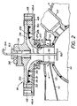
- FIG 1 is a vertical cross sectional view of a pulsatory burner according to the invention provided in the partly shown water space in a hot water boiler, and
- FIG 2 is a fragmentary vertical cross sectional view of the pulsatory burner modified for the use of gas.
- In FIG 1 a
hot water boiler 10 with awater space 12 formed by a tank 11 is fragmentarily shown, apulsatory burner 13 being provided in the water space. The pulsatory burner comprises aspherical combustion chamber 14 having anopening 15 which is connected to a flue gas outlet by aconduit 16, said flue gas outlet forming a Helmholz-resonator together with the combustion chamber, and further having acylindrical neck 17 provided on the top thereof, which is attached to the wall 11 and supports anonreturn valve 18. This valve comprises a valve body which consists of alower part 19 and acover 20 which are detachably connected by means of bolt joints. The lower part is inserted into theneck 17 at a cylindrical socket 21, sealing O-rings 22 being provided between the socket and the neck, and the lower part being attached to theneck 17 by means of a snap-inlock 23 which engages outwardly projectingflanges interior surface portion 27 which joins the cylindrical interior surface of theneck 17. - In the seat a number of air inlet openings 28 are provided, and for the control of the air flow therethrough a relatively thin,
circular valve ring 29 is provided which has to be elastically flexible and can consist of metal, or plastic, or some composite material. The openings 28 are distributed along a circle, and on both sides of the openings elastic O-rings ring 32 is also provided which is received in an annular groove in the seat, and the outer edge of the valve ring is received between thecover 20 and this latter O-ring. The cover forms a centrally projecting cylindrical portion on the upper side thereof with a downwards open central threadedbottom hole 34 into which an injection nozzle 35 is screwed, and to the bottom hole 34 a threadedcross bore 36 connects for the connection of aconduit 37 for supply of fuel oil (FIG 1). The injection nozzle extends centrally into the socket 21 and opens into a constriction in the passage through the socket, formed by thesurface 27, which forms a kind of a venturi nozzle. - The
cover 20 has on the lower side thereof a ring shaped recess which is bounded by acurved surface 38 the shape of which is adapted to the shape of thecurved surface 27 so that, around the injection nozzle 35, there is a ring shaped passage which extends from the air inlet openings 28 down into theneck 17 which forms the air inlet to the combustion chamber. - Inside the
water space 12 quite close to the wall 11 the neck is surrounded on the outside thereof by a downwardsopen cover 40 which is connected to aconduit 41 provided along the wall 11, atube 42 for output hot water from the boiler being connected to said conduit. The water which is heated in thewater space 12 of the boiler by means of the pulsatory burner is thus forced to pass into the radiator system through thetube 42 in contact with the outside of theneck 17 inside thecover 40 in order that this water will cool the neck, which is made relatively short as disclosed in FIG 1. - Diametrically opposite to the
neck 17 on the lower side of the combustion chamber there is provided asocket 43 with a threadedbore 44 into which astud 45 is screwed which projects into the combustion chamber towards the centre thereof but ends at a distance therefrom. In the inner end thereof the stud supports aplate 46 shaped as a truncated cone with the small end upwards. The plate should consist of a heat resistant material. Thus, the oil which is ejected from the injection nozzle 35 is directed into the combustion chamber against this plate which serves as an ignition body for the oil. Previously, a plate of cast iron has been provided as an ignition body. Such a plate has a large thermal inertia and takes a long time to be hot. The consequence thereof is that poor combustion after starting of the pulsatory burner is obtained (the boiler smokes). Furthermore, the construction is expensive and provides a non-desired heat radiation towards the nonreturn valve. - On the combustion chamber there is also provided a
casing 47 for the mounting of an ignition electrode. - In order to create optimal conditions for the combustion in the pulsatory burner when this is made with a water cooled
short neck 17 in the way described above, the dimensioning of the pulsatory burner is critical. Thus, critical parameters are the ratio between the internal diameter of theneck 17 and the internal diameter of thecombustion chamber 14, the ratio between the diameter of theplate 46 and the internal diameter of the combustion chamber, and the ratio between the distance from theplate 46 to the top of the combustion chamber and the internal diameter of the combustion chamber. Also the distance from the tip of the injection nozzle to the combustion chamber has significance. - For a combustion chamber with an internal diameter of 130 mm the following exemplifying numbers can be given:
- The diameter of the
plate 46 can be between 20 and 60 mm which gives a ratio between the diameter of the plate and the internal diameter of the combustion chamber ranging from 0.15 to 0.46. - The distance from the top of the
plate 46 to the top of the combustion chamber can be 64 - 85 mm which gives a ratio between this distance and the internal diameter of the combustion chamber ranging from 0.49 to 0.65. - The internal diameter of the neck 17 (the diameter of the air inlet) can be between 20 and 60 which gives a ratio between this diameter and the internal diameter of the combustion chamber between 0.15 and 0.35.
- The distance between the nozzle tip and the combustion chamber should be 10 - 35 mm which corresponds to a ratio between this distance and the internal diameter of the neck of 0.17 - 1.75.
- The function of the pulsatory burner is well known and, therefore, will not be further described since the pulsatory burner described herein as to the method of functioning does not differ in principle from previously known pulsatory burners of the type referred to herein. The
valve ring 29 opens and closes under the influence of the phases of positive and negative pressure which are obtained in connection with the pulsatory combustion in the combustion chamber. Optimization of the combustion conditions requires, in addition to that previously mentioned, that the valve closes abruptly when abutting the valve seat and then seals tightly against the seat. Good sealing against the valve seat can be achieved by the valve ring having a large contact surface against the seat in the closed position which, however, entails a risk for the valve ring to stick to the supporting surface on the valve seat. On the other hand, if the supporting surface on the valve seat is decreased the sealing will be less satisfactory and there is a risk of deformation of the valve ring generating large bending stress therein. In the embodiment of the non return valve described herein which in principle coincides with that described in SE-B-435 098 as comprising a valve ring which is mounted between two supports at the outer edge thereof, namely between thecover 20 and the O-ring 32, good sealing is achieved against the valve seat at the same time as the risk for the valve ring to stick to the seat is eliminated by the valve ring in the closed position thereof engaging the two O-rings - The described pulsatory burner is constructed for combustion of oil or another liquid fluid but can also be arranged for the combustion of gaseous fuel. In the gas variant the pulsatory burner can be constructed in a manner known per se as shown in FIG 2.
- According to FIG 2 the pulsatory burner is arranged for the combustion of gas which is supplied through a
ring passage 48 provided in thelower part 19 and having a number of uniformly distributedoutflow openings 48A which open on the cover side of the lower part into apassage 49 which is defined between the lower side of the lower part and a plate or apanel 50 attached to the lower part. Thebore 36 then is plugged. The air to the combustion chamber is aspirated via the nonreturn valve through this passage the gas being mixed with the aspirated air. In the upper part 20 a so calledignition button 52 made of a heat resistant material is suspended in the combustion chamber by means of a shank 51, said ignition button being located beneath the opening of the inlet passage at a distance of 10 - 25 mm from the top of the combustion chamber, which corresponds to a ratio between said distance and the internal diameter of the combustion chamber of 0.07 - 0.2. The shank is attached to the upper part by means of aninsulator 53 and is connected by means of aconduit 54 to a flame monitor system. The ignition button, the diameter thereof being 20 - 30 mm, serves to ignite the inflow of the gas mixture but can also, as shown herein, serve as an electrode for ionisation type monitoring of the combustion in the combustion chamber in a way known per se. - If the shank 51 with the
ignition button 52 is removed and replaced by an oil nozzle, the pulsatory burner can easily be converted from gas firing to oil firing.
Claims (5)
- Boiler containing a pulsatory burner which is mounted in the water space (12) of the boiler, comprising a combustion chamber (14) with a neck (17) provided as an air inlet, a nonreturn valve (18) controlling the air flow through the air inlet to the combustion chamber, said nonreturn valve having a seat (26) concentric with the air inlet, at least one air inlet opening (28), a plane, relatively thin circular valve ring (29) which is elastically flexible and, in the closed position of the valve, engages the seat and keeps the air inlet opening closed but can be operated to an open position by depression in the combustion chamber, and an outlet (40, 41) for hot water from the water space (12) said outlet being provided around the neck (17) for the cooling thereof.
- Boiler according to claim 1, wherein the air inlet in the neck (17) has a circular cross section and the combustion chamber (14) is spherical internally, and wherein the ration between the diameter of the air inlet and the internal diameter of the combustion chamber is of the order of 0.15 . 0.35.
- Boiler according to claim 1, wherein the air inlet is provided with a constriction bounded by a curved surface (27).
- Boiler according to claim 1, wherein elastic O-rings (30, 31) are provided in the valve seat (26) on both sides of the air inlet opening or openings (28), respectively, as engagement surfaces for the valve ring (29).
- Boiler according to claim 1 with a fuel nozzle (35) opening into the air inlet (17), wherein the ratio between the distance from the fuel nozzle to the top of the combustion chamber and the internal diameter of the neck (17) is 0.17 - 1.75.
Priority Applications (1)
| Application Number | Priority Date | Filing Date | Title |
|---|---|---|---|
| AT90913344T ATE91332T1 (en) | 1989-08-24 | 1990-08-21 | PULSATING BURNER. |
Applications Claiming Priority (2)
| Application Number | Priority Date | Filing Date | Title |
|---|---|---|---|
| SE8902811A SE464540B (en) | 1989-08-24 | 1989-08-24 | SCRUBBURGERS FOR HOT WATER BOILERS, WHILE NECK COOLED BY AN OUTPUT FOR HOT WATER |
| SE8902811 | 1989-08-24 |
Publications (2)
| Publication Number | Publication Date |
|---|---|
| EP0489820A1 EP0489820A1 (en) | 1992-06-17 |
| EP0489820B1 true EP0489820B1 (en) | 1993-07-07 |
Family
ID=20376727
Family Applications (1)
| Application Number | Title | Priority Date | Filing Date |
|---|---|---|---|
| EP90913344A Expired - Lifetime EP0489820B1 (en) | 1989-08-24 | 1990-08-21 | Pulsatory burner |
Country Status (7)
| Country | Link |
|---|---|
| US (1) | US5189989A (en) |
| EP (1) | EP0489820B1 (en) |
| CA (1) | CA2064241A1 (en) |
| DE (1) | DE69002166T2 (en) |
| FI (1) | FI93271C (en) |
| SE (1) | SE464540B (en) |
| WO (1) | WO1991002924A1 (en) |
Families Citing this family (4)
| Publication number | Priority date | Publication date | Assignee | Title |
|---|---|---|---|---|
| SE464541B (en) * | 1990-04-04 | 1991-05-06 | Pulsonex Ab | PULSBRAENNARE |
| US5448969A (en) * | 1994-03-23 | 1995-09-12 | Bowles Fluidics Corporation | Fluidic burner |
| FR2936300B1 (en) * | 2008-09-25 | 2010-10-22 | Muller & Cie Soc | PULSATORY BOILER |
| FR2936299B1 (en) * | 2008-09-25 | 2010-12-24 | Muller & Cie Soc | PULSATORY BOILER WITH FLAP VALVE |
Family Cites Families (8)
| Publication number | Priority date | Publication date | Assignee | Title |
|---|---|---|---|---|
| DE933651C (en) * | 1950-08-08 | 1955-09-29 | Snecma | Steam boiler for generating steam or the like. |
| DE1242318B (en) * | 1962-12-24 | 1967-06-15 | Junkers & Co | Burner system for pulsating combustion |
| US3267985A (en) * | 1964-03-12 | 1966-08-23 | John A Kitchen | Pulse combustion apparatus |
| US4488865A (en) * | 1980-12-22 | 1984-12-18 | Arkansas Patents, Inc. | Pulsing combustion |
| EP0107538B1 (en) * | 1982-09-30 | 1987-01-14 | Celette S.A. | Device for checking the position of the shock absorber heads of the front suspension of a vehicle |
| SE435098B (en) * | 1982-12-30 | 1984-09-03 | Mareck Bv | BACK VALVE IN AIR INLET FOR A SCRUBBURNER |
| JPS6152508A (en) * | 1984-08-21 | 1986-03-15 | Toshiba Corp | Pulsating combustion apparatus |
| EP0227699B1 (en) * | 1985-06-12 | 1989-01-04 | PLETZER, Georg | Furnace device |
-
1989
- 1989-08-24 SE SE8902811A patent/SE464540B/en not_active IP Right Cessation
-
1990
- 1990-08-21 EP EP90913344A patent/EP0489820B1/en not_active Expired - Lifetime
- 1990-08-21 US US07/809,523 patent/US5189989A/en not_active Expired - Fee Related
- 1990-08-21 DE DE90913344T patent/DE69002166T2/en not_active Expired - Fee Related
- 1990-08-21 WO PCT/SE1990/000541 patent/WO1991002924A1/en active IP Right Grant
- 1990-08-21 CA CA002064241A patent/CA2064241A1/en not_active Abandoned
-
1992
- 1992-02-17 FI FI920679A patent/FI93271C/en active
Also Published As
| Publication number | Publication date |
|---|---|
| SE8902811D0 (en) | 1989-08-24 |
| FI93271B (en) | 1994-11-30 |
| SE464540B (en) | 1991-05-06 |
| US5189989A (en) | 1993-03-02 |
| SE8902811L (en) | 1991-02-25 |
| EP0489820A1 (en) | 1992-06-17 |
| FI920679A0 (en) | 1992-02-17 |
| FI93271C (en) | 1995-03-10 |
| WO1991002924A1 (en) | 1991-03-07 |
| CA2064241A1 (en) | 1991-02-25 |
| DE69002166D1 (en) | 1993-08-12 |
| DE69002166T2 (en) | 1994-02-03 |
Similar Documents
| Publication | Publication Date | Title |
|---|---|---|
| CA1323257C (en) | Water heater construction | |
| EP0489820B1 (en) | Pulsatory burner | |
| US3485567A (en) | Liquid fuel burning appliance and components therefor | |
| JP3096749B2 (en) | Burner | |
| CN211600793U (en) | Normally open fire device and gas stove thereof | |
| US4583938A (en) | Gas burner of the pre-mixture type with flame control and utilization of that burner especially in an immersed pipe installation | |
| RU2321800C1 (en) | Gas burner | |
| RU213218U1 (en) | MULTIPLE INJECTION BURNER | |
| KR100227262B1 (en) | Nozzle body of gas burner | |
| RU70345U1 (en) | GAS BURNER DEVICE | |
| KR0124475Y1 (en) | Control apparatus for primary air control in gas range | |
| KR830000601Y1 (en) | Cast iron section boiler for pressurized air blowing | |
| RU271U1 (en) | Vapor burner | |
| US3144076A (en) | Flame retaining gas burner | |
| KR200141457Y1 (en) | Apparatus for supplying the primary air in a burner | |
| RU94664U1 (en) | GAS BURNER DEVICE | |
| JPS6322460Y2 (en) | ||
| KR0135816Y1 (en) | High thermal power burner | |
| RU23189U1 (en) | GAS-USING DEVICE SAFETY AUTOMATION | |
| JPS6116887B2 (en) | ||
| US967595A (en) | Oil-burner. | |
| JPS6410730B2 (en) | ||
| KR100249225B1 (en) | Device for activating flame of oil burner | |
| KR940002810Y1 (en) | Constant and instantaneous kerosene vaporizing burner | |
| KR200159547Y1 (en) | A burner for standing boiler |
Legal Events
| Date | Code | Title | Description |
|---|---|---|---|
| PUAI | Public reference made under article 153(3) epc to a published international application that has entered the european phase |
Free format text: ORIGINAL CODE: 0009012 |
|
| 17P | Request for examination filed |
Effective date: 19920114 |
|
| AK | Designated contracting states |
Kind code of ref document: A1 Designated state(s): AT BE CH DE DK ES FR GB IT LI LU NL SE |
|
| 17Q | First examination report despatched |
Effective date: 19921006 |
|
| GRAA | (expected) grant |
Free format text: ORIGINAL CODE: 0009210 |
|
| AK | Designated contracting states |
Kind code of ref document: B1 Designated state(s): AT BE CH DE DK ES FR GB IT LI LU NL SE |
|
| PG25 | Lapsed in a contracting state [announced via postgrant information from national office to epo] |
Ref country code: NL Effective date: 19930707 Ref country code: ES Free format text: THE PATENT HAS BEEN ANNULLED BY A DECISION OF A NATIONAL AUTHORITY Effective date: 19930707 Ref country code: DK Effective date: 19930707 |
|
| REF | Corresponds to: |
Ref document number: 91332 Country of ref document: AT Date of ref document: 19930715 Kind code of ref document: T |
|
| REF | Corresponds to: |
Ref document number: 69002166 Country of ref document: DE Date of ref document: 19930812 |
|
| PG25 | Lapsed in a contracting state [announced via postgrant information from national office to epo] |
Ref country code: LU Free format text: LAPSE BECAUSE OF NON-PAYMENT OF DUE FEES Effective date: 19930831 |
|
| ITF | It: translation for a ep patent filed | ||
| ET | Fr: translation filed | ||
| NLV1 | Nl: lapsed or annulled due to failure to fulfill the requirements of art. 29p and 29m of the patents act | ||
| PLBE | No opposition filed within time limit |
Free format text: ORIGINAL CODE: 0009261 |
|
| STAA | Information on the status of an ep patent application or granted ep patent |
Free format text: STATUS: NO OPPOSITION FILED WITHIN TIME LIMIT |
|
| 26N | No opposition filed | ||
| PG25 | Lapsed in a contracting state [announced via postgrant information from national office to epo] |
Ref country code: GB Effective date: 19940821 |
|
| EAL | Se: european patent in force in sweden |
Ref document number: 90913344.9 |
|
| GBPC | Gb: european patent ceased through non-payment of renewal fee |
Effective date: 19940821 |
|
| REG | Reference to a national code |
Ref country code: CH Ref legal event code: PUE Owner name: PULSONEX AB TRANSFER- PYROPAC AG |
|
| REG | Reference to a national code |
Ref country code: FR Ref legal event code: CA |
|
| REG | Reference to a national code |
Ref country code: FR Ref legal event code: TP |
|
| REG | Reference to a national code |
Ref country code: CH Ref legal event code: NV Representative=s name: HUG INTERLIZENZ AG |
|
| PGFP | Annual fee paid to national office [announced via postgrant information from national office to epo] |
Ref country code: FR Payment date: 19990709 Year of fee payment: 10 |
|
| PGFP | Annual fee paid to national office [announced via postgrant information from national office to epo] |
Ref country code: BE Payment date: 19990818 Year of fee payment: 10 |
|
| PG25 | Lapsed in a contracting state [announced via postgrant information from national office to epo] |
Ref country code: BE Free format text: LAPSE BECAUSE OF NON-PAYMENT OF DUE FEES Effective date: 20000831 |
|
| BERE | Be: lapsed |
Owner name: PYROPAC A.G. Effective date: 20000831 |
|
| PG25 | Lapsed in a contracting state [announced via postgrant information from national office to epo] |
Ref country code: FR Free format text: LAPSE BECAUSE OF NON-PAYMENT OF DUE FEES Effective date: 20010430 |
|
| REG | Reference to a national code |
Ref country code: FR Ref legal event code: ST |
|
| PGFP | Annual fee paid to national office [announced via postgrant information from national office to epo] |
Ref country code: CH Payment date: 20030617 Year of fee payment: 14 |
|
| PGFP | Annual fee paid to national office [announced via postgrant information from national office to epo] |
Ref country code: DE Payment date: 20030717 Year of fee payment: 14 |
|
| PGFP | Annual fee paid to national office [announced via postgrant information from national office to epo] |
Ref country code: SE Payment date: 20030722 Year of fee payment: 14 |
|
| PGFP | Annual fee paid to national office [announced via postgrant information from national office to epo] |
Ref country code: AT Payment date: 20030801 Year of fee payment: 14 |
|
| PG25 | Lapsed in a contracting state [announced via postgrant information from national office to epo] |
Ref country code: AT Free format text: LAPSE BECAUSE OF NON-PAYMENT OF DUE FEES Effective date: 20040821 |
|
| PG25 | Lapsed in a contracting state [announced via postgrant information from national office to epo] |
Ref country code: SE Free format text: LAPSE BECAUSE OF NON-PAYMENT OF DUE FEES Effective date: 20040822 |
|
| PG25 | Lapsed in a contracting state [announced via postgrant information from national office to epo] |
Ref country code: LI Free format text: LAPSE BECAUSE OF NON-PAYMENT OF DUE FEES Effective date: 20040831 Ref country code: CH Free format text: LAPSE BECAUSE OF NON-PAYMENT OF DUE FEES Effective date: 20040831 |
|
| PG25 | Lapsed in a contracting state [announced via postgrant information from national office to epo] |
Ref country code: DE Free format text: LAPSE BECAUSE OF NON-PAYMENT OF DUE FEES Effective date: 20050301 |
|
| EUG | Se: european patent has lapsed | ||
| REG | Reference to a national code |
Ref country code: CH Ref legal event code: PL |
|
| PG25 | Lapsed in a contracting state [announced via postgrant information from national office to epo] |
Ref country code: IT Free format text: LAPSE BECAUSE OF NON-PAYMENT OF DUE FEES;WARNING: LAPSES OF ITALIAN PATENTS WITH EFFECTIVE DATE BEFORE 2007 MAY HAVE OCCURRED AT ANY TIME BEFORE 2007. THE CORRECT EFFECTIVE DATE MAY BE DIFFERENT FROM THE ONE RECORDED. Effective date: 20050821 |