EP0489712B1 - Missile steering arrangement using thrust control - Google Patents
Missile steering arrangement using thrust control Download PDFInfo
- Publication number
- EP0489712B1 EP0489712B1 EP92101745A EP92101745A EP0489712B1 EP 0489712 B1 EP0489712 B1 EP 0489712B1 EP 92101745 A EP92101745 A EP 92101745A EP 92101745 A EP92101745 A EP 92101745A EP 0489712 B1 EP0489712 B1 EP 0489712B1
- Authority
- EP
- European Patent Office
- Prior art keywords
- control
- nozzle
- control system
- reaction
- distal end
- Prior art date
- Legal status (The legal status is an assumption and is not a legal conclusion. Google has not performed a legal analysis and makes no representation as to the accuracy of the status listed.)
- Expired - Lifetime
Links
Images

Classifications
-
- F—MECHANICAL ENGINEERING; LIGHTING; HEATING; WEAPONS; BLASTING
- F02—COMBUSTION ENGINES; HOT-GAS OR COMBUSTION-PRODUCT ENGINE PLANTS
- F02K—JET-PROPULSION PLANTS
- F02K9/00—Rocket-engine plants, i.e. plants carrying both fuel and oxidant therefor; Control thereof
- F02K9/80—Rocket-engine plants, i.e. plants carrying both fuel and oxidant therefor; Control thereof characterised by thrust or thrust vector control
- F02K9/88—Rocket-engine plants, i.e. plants carrying both fuel and oxidant therefor; Control thereof characterised by thrust or thrust vector control using auxiliary rocket nozzles
-
- F—MECHANICAL ENGINEERING; LIGHTING; HEATING; WEAPONS; BLASTING
- F42—AMMUNITION; BLASTING
- F42B—EXPLOSIVE CHARGES, e.g. FOR BLASTING, FIREWORKS, AMMUNITION
- F42B10/00—Means for influencing, e.g. improving, the aerodynamic properties of projectiles or missiles; Arrangements on projectiles or missiles for stabilising, steering, range-reducing, range-increasing or fall-retarding
- F42B10/60—Steering arrangements
- F42B10/66—Steering by varying intensity or direction of thrust
- F42B10/663—Steering by varying intensity or direction of thrust using a plurality of transversally acting auxiliary nozzles, which are opened or closed by valves
Definitions
- This invention relates to a reaction control system for a projectile, for example a missile or a mortar round and to projectiles including such systems.
- Directional control of missiles in flight may be achieved either aerodynamically using movable control surfaces, e.g. fins, or by using a reaction control system in which control thrusts are generated by emitting a reaction gas transversely of the missile.
- movable control surfaces e.g. fins
- control thrusts are generated by emitting a reaction gas transversely of the missile.
- single shot squibs or pulsed units This is believed to limit the degree and accuracy of control and requires the missile autopilot to be specifically designed to deal with this method of control.
- the magnitude of the thrust remains generally the same; the only control available is control of the length of the impulse.
- Studies conducted by the applicants show that there is a need for a reaction control system which produces a thrust whose magnitude may be varied continuously. Furthermore, there is a need for such a system in which the relationship between the movement of the member controlling the reaction control system and the thrust thereby is generally compatible with that of a fin assembly so that the reaction system may be controlled by an existing autopilot without major modification.
- EP-A-244971 discloses a reaction control system according to the preamble of claim 1 and in which lost motion is provided between a lever and a pinion in the drive train between an electromechanical actuator and a valve control element, for the express purpose of avoiding the need to match the strokes of the actuator and the valve.
- a nozzle assembly including a nozzle control element movable to control the flow therethrough, and comprising a sealing end and a distal end, a control member for moving said nozzle control element, and lost motion means in the control path between said control member and said nozzle control element, said lost motion means comprises bias means arranged between said sealing end and said distal end, whereby said distal end may move relative to said sealing end against said bias.
- a preferred embodiment of the system is particularly useful where a projectile requires the control function exerted by the aerodynamic fins either to be augmented by the reaction control system, e.g., to execute a terminal manoeuvre, or to be replaced thereby when the projectile is travelling too slowly for the aerodynamic fins to be effective, e.g. at launch.
- reaction control system is intended to be operated in conjuction with a fin assembly by an autopilot.
- the reaction control system may however also be used in missiles which do not incorporate a fin assembly.
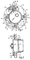
- FIGS 1 and 2 illustrate an actuator assembly 10 for a reaction control system.
- the assembly 10 comprises a casing 12 which houses a gas generator 14 and which includes an outer flange 16.
- the outer flange carries four thruster assemblies 18 equispaced around the periphery of the missile.
- Each thruster assembly 18 comprises a pair of aligned nozzles 20 connected by conduits 22 to the gas generator 14 and each arranged to exhaust in opposite directions.
- the flow of gas from gas generator 14 through each nozzle 20 is controlled by means of a piston 24 slidably mounted with respect to the nozzle so as to be movable to vary the effective thrust area of the nozzle and thus the thrust generated.
- Each piston is continuously movable with respect to the throat of the associated nozzle - i.e.
- Each piston is provided with a conical sealing end 26 and a distal end 28.
- the respective distal ends of the pistons 24 of a pair of nozzles are acted upon by a cam member 30 rotatably secured to the flange 16 and attached to an operating lever 32. Rotation of the cam member causes inverse operation of the pistons, i.e. one piston moves to increase the flow through its associated nozzle as the other piston moves to decrease the flow through its associated nozzle.
- a spring arrangement 34 is provided between the sealing end 26 and the distal end 28 and is arranged so that in normal operation there is no relative movement between the sealing end and the distal end, but if the sealing end 26 should seize and be prevented from movement, the distal end may move relative to the sealing end 28 against the bias of the spring 34 so that the cam member 30 is not prevented from rotating.
- the four thruster assemblies 18 are equispaced around the periphery of the missile so that two assemblies (the upper and lower assemblies as viewed in Figure 1) lie in spaced planes parallel to the yaw plane and two assemblies (the left hand and right hand assemblies as viewed in Figure 1) lie in spaced planes parallel to the pitch plane.
- the actuator assembly illustrated in Figures 1 and is mounted forwardly of the centre of gravity of the missile.
- the upper and lower assemblies effect control in the yaw sense and the left and right hand assemblies effect control in the pitch sense. If the upper and lower assemblies are not operated to generate the same magnitude of thrust in parallel directions, then a component of roll torque is generated. If the thrust generated by the upper and lower assemblies is equal and opposite then a simple roll torque will be generated. Similar considerations apply to operation of the left and right hand assemblies.
- the gas generator may be of any suitable form; in the illustrated embodiment, it takes the form of a hot gas generator which is ignited by means of an igniter 36.
- a burster disc assembly 38 is provided for safety purposes.
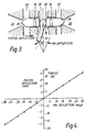
- Figure 3 illustrates schematically a single assembly showing the operating lever 32 and the cam 30. It will be understood that the direction and magnitude of the thrust vector generated by the assembly is dependent on the position of the operating lever 32.
- Figure 4 illustrates the variation of the thrust developed with the deflection of the piston; it will be seen that the thrust varies proportionally with movement of the piston. It should be noted that this is for the purposes of illustration only and that other characteristics will result for different designs.
- Figure 5 illustrates a missile with a reaction control assembly 10 located forwardly of the centre of gravity 40 of the missile and an aft fin assembly 42 comprising four movable fins 44 arranged at the aft of a missile.
- the fins are oriented around the missile body so that operation of one set of diametrically opposed fins in unison effects control in the yaw sense whilst operation of the other set of diametrically opposed fins in unison effects control in the pitch sense. Differential operation of either set of fins effects control in the roll sense.
- Figure 6 illustrates a navigation system for the missile of Figure 5.
- An autopilot 46 calculates the control movements required for the desired course corrections and controls a servomotor assembly 48 which controls movement of the fins 44 and also movement of the operating levers 32 of the associated thruster assembly.
- each of the thruster assemblies is operable to impart a control moment which is similar to that imparted by rotation of a fin member when the missile is in normal flight.
- the control function exerted by thruster assembly 18' is analogous to that exerted by movable fin 44' etc.
- the thrust developed on deflection of the fin 44 is illustrated in Figure 4. It will be seen that, as with movement of the pistons of the thruster assemblies, that thrust/movement relationship is essentially linear for this example and that the thrust/movement characteristics for the thruster assembly are similar to those developed by angular movement of the fin.
- the reaction control system may provide a thrust which is proportional to the fin deflections, so enhancing the control effectiveness of the fins. This is particularly useful when the missile is travelling too slowly for the fins to be effective e.g. at launch, or where an extra amount of control is desired e.g. for a terminal manoeuvre. Because of the similarity between the movement/thrust characteristics of the fins and reaction control system this method of control augmentation may be added to a missile with little or no change to the autopilot.
- the spring 34 override mechanism in the reaction control system serves an important purpose because it prevents total failure in the event of a failure of the reaction control system, as it enables the movable fin assembly to continue operating.
- the spring override mechanism is of particular benefit where two nozzles are operated in back to back fashion by a single actuator as in the arrangements 18 of Figures 1 to 6, because in these types of arrangement the mechanism may compensate for slight dimensional inaccuracies of the piston members, the cam mechanism and/or the housing defining the bores in which the pistons slide which might otherwise jam or damage the drive motor when moving towards an end position.
- the mechanism means that the designer can ensure that the pistons may be moved into engagement with the nozzle throat, thus closing it, without jamming the servo control system or preventing movement of the corresponding fin member.
- the reaction gas may be a cold or hot gas and the storage reservoir or gas generator may be integrated with the nozzle units to provide a compact control package.
- the reaction gas may be bled off the main missile rocket motor; indeed a plurality of thruster assemblies may be inclined rearwards to provide not only lateral control but also the main source of rocket propulsion.
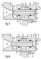
- FIGS. 7 and 8 illustrate an embodiment of control thruster assembly in the fully open and fully closed positions respectively.
- the assembly comprises a housing 50 defining an outlet throat 52 and a fluid supply manifold 54, and a plunger 56 which is slidably located in a pair of spaced bores 58,60 each of which includes a gas seal 62.
- the bore 60 at the rear of the plunger 56 is closed to define a variable volume chamber 63, together with the rear end of the plunger 56.
- a pressure balance bore 64 interconnects the two axial end faces of the plunger 56 to tend to equalise the pressure forces acting on the plunger 56.
- a pressure transducer 66 may be provided to sense the pressure in the variable volume chamber 63, the sensed pressure being a measure of the pressure of the fluid in the outlet throat 52 and also of the displacement of the plunger 56.
- the housing 50 is relieved and receives for limited axial movement an actuating lever 68 secured to the plunger 56.
- the actuating lever 68 includes a rack portion 70 which engages the pinion 72 of a drive motor (not shown) for driving the plunger between the positions shown in Figures 7 and 8.
- a plunger position sensor linkage 74 may be connected to the actuating lever 68 for determining the position of the plunger.
- the thrust can be switched “on” or “off” or modulated by movement of the plunger 56.
- the drive may be in the form of a servo motor/gear box, whilst for a bang-bang system a stepping motor drive connected directly to the plunger may be used.
- the magnitude of the sampled pressure will be a function of the plunger displacement. With this system only a modestly powered servo actuator drive will be required for the plunger as the resultant pressure force acting on the plunger will be low. Inthe "off" position, ambient pressure will act on both ends of the plunger.
- Plunger position data may be determined from a position sensor connected to the position sensor linkage 74 or it may be derived from a pressure transducer 66 which samples the pressure at the outlet throat via the pressure balance bore 64.
- refractory or ceramic materials may be used in the assembly.
- the gas supply to the thruster assembly may be taken from the main propulsion rocket motor system or from a dedicated hot or cool propellant gas supply.
- the number of thrusters will be a function of the particular control system required.
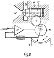
- FIG 9 is a schematic illustration of a thruster assembly of the type illustrated in Figures 7 and 8 configured in a servo-control loop. Many of the component parts are similar and will not be described in detail again.
- the plunger 56 has an integral rack portion 70 which meshes with a pinion 72 connected via a gear train to an electric motor 80.
- a potentiometer 81 associated with the electric motor 80 provides a position feedback signal which is supplied to one input of a differential amplifier 82 which controls the motor 80.
- the position servo can control a single unit as shown with a pressure balance bore 64 to reduce actuation forces, or two units arranged back-to-back as in the arrangements of Figures 1 to 6, where the pressure balance bore would not be necessary.
- a servo control loop of the type illustrated in Figure 9 could be used to drive the cam mechanism of the arrangements of Figures 1 to 6.
- reaction control systems described herein may be coupled to operate in tandem with the fin control system or they may operate independently of any fin control system.
Description
- This invention relates to a reaction control system for a projectile, for example a missile or a mortar round and to projectiles including such systems.
- Directional control of missiles in flight may be achieved either aerodynamically using movable control surfaces, e.g. fins, or by using a reaction control system in which control thrusts are generated by emitting a reaction gas transversely of the missile. In the known examples of the latter method of control it is usual to employ single shot squibs or pulsed units. This is believed to limit the degree and accuracy of control and requires the missile autopilot to be specifically designed to deal with this method of control. In these systems the magnitude of the thrust remains generally the same; the only control available is control of the length of the impulse. Studies conducted by the applicants show that there is a need for a reaction control system which produces a thrust whose magnitude may be varied continuously. Furthermore, there is a need for such a system in which the relationship between the movement of the member controlling the reaction control system and the thrust thereby is generally compatible with that of a fin assembly so that the reaction system may be controlled by an existing autopilot without major modification.
- EP-A-244971 discloses a reaction control system according to the preamble of
claim 1 and in which lost motion is provided between a lever and a pinion in the drive train between an electromechanical actuator and a valve control element, for the express purpose of avoiding the need to match the strokes of the actuator and the valve. - According to the invention, there is provided a nozzle assembly including a nozzle control element movable to control the flow therethrough, and comprising a sealing end and a distal end, a control member for moving said nozzle control element, and lost motion means in the control path between said control member and said nozzle control element, said lost motion means comprises bias means arranged between said sealing end and said distal end, whereby said distal end may move relative to said sealing end against said bias.
- A preferred embodiment of the system is particularly useful where a projectile requires the control function exerted by the aerodynamic fins either to be augmented by the reaction control system, e.g., to execute a terminal manoeuvre, or to be replaced thereby when the projectile is travelling too slowly for the aerodynamic fins to be effective, e.g. at launch.
- The invention will now be described by way of non-limiting example, reference being made to the accompanying drawings, in which:-
- Figure 1 is a schematic rear view of an actuator assembly of an example of reaction control system according to this invention;
- Figure 2 is a section view of the actuator assembly of Figure 1 taken on lines II-II;
- Figure 3 is a diagrammatic view of the arrangement of one pair of nozzles in the arrangement of Figures 1 and 2;
- Figure 4 is a graph illustrating the relationship between piston deflection, thrust and fin deflection for an example of a missile incorporating a reaction control system and a fin assembly;
- Figure 5 is a diagrammatic view of an example of a missile incorporating a reaction control system and a fin assembly;
- Figure 6 is a block diagram of the control system of the missile of Figure 5;
- Figures 7 and 8 show an example of a control thruster assembly in the open and closed positions repectively; and
- Figure 9 shows schematically an example of a control thruster assembly configured in a servo loop.
- Referring to the Figures, the illustrated embodiment of reaction control system is intended to be operated in conjuction with a fin assembly by an autopilot. The reaction control system may however also be used in missiles which do not incorporate a fin assembly.
- Figures 1 and 2 illustrate an
actuator assembly 10 for a reaction control system. Theassembly 10 comprises acasing 12 which houses agas generator 14 and which includes anouter flange 16. The outer flange carries four thruster assemblies 18 equispaced around the periphery of the missile. Eachthruster assembly 18 comprises a pair of alignednozzles 20 connected byconduits 22 to thegas generator 14 and each arranged to exhaust in opposite directions. The flow of gas fromgas generator 14 through eachnozzle 20 is controlled by means of apiston 24 slidably mounted with respect to the nozzle so as to be movable to vary the effective thrust area of the nozzle and thus the thrust generated. Each piston is continuously movable with respect to the throat of the associated nozzle - i.e. it can assume any position between fully open and fully closed. Each piston is provided with aconical sealing end 26 and adistal end 28. The respective distal ends of thepistons 24 of a pair of nozzles are acted upon by acam member 30 rotatably secured to theflange 16 and attached to anoperating lever 32. Rotation of the cam member causes inverse operation of the pistons, i.e. one piston moves to increase the flow through its associated nozzle as the other piston moves to decrease the flow through its associated nozzle. Aspring arrangement 34 is provided between the sealingend 26 and thedistal end 28 and is arranged so that in normal operation there is no relative movement between the sealing end and the distal end, but if the sealingend 26 should seize and be prevented from movement, the distal end may move relative to the sealingend 28 against the bias of thespring 34 so that thecam member 30 is not prevented from rotating. - The four
thruster assemblies 18 are equispaced around the periphery of the missile so that two assemblies (the upper and lower assemblies as viewed in Figure 1) lie in spaced planes parallel to the yaw plane and two assemblies (the left hand and right hand assemblies as viewed in Figure 1) lie in spaced planes parallel to the pitch plane. In use, as illustrated in Figure 5, the actuator assembly illustrated in Figures 1 and is mounted forwardly of the centre of gravity of the missile. Hence, when used in unison, the upper and lower assemblies effect control in the yaw sense and the left and right hand assemblies effect control in the pitch sense. If the upper and lower assemblies are not operated to generate the same magnitude of thrust in parallel directions, then a component of roll torque is generated. If the thrust generated by the upper and lower assemblies is equal and opposite then a simple roll torque will be generated. Similar considerations apply to operation of the left and right hand assemblies. - The gas generator may be of any suitable form; in the illustrated embodiment, it takes the form of a hot gas generator which is ignited by means of an
igniter 36. Aburster disc assembly 38 is provided for safety purposes. - Figure 3 illustrates schematically a single assembly showing the
operating lever 32 and thecam 30. It will be understood that the direction and magnitude of the thrust vector generated by the assembly is dependent on the position of theoperating lever 32. - Figure 4 illustrates the variation of the thrust developed with the deflection of the piston; it will be seen that the thrust varies proportionally with movement of the piston. It should be noted that this is for the purposes of illustration only and that other characteristics will result for different designs.
- Figure 5 illustrates a missile with a
reaction control assembly 10 located forwardly of the centre ofgravity 40 of the missile and anaft fin assembly 42 comprising fourmovable fins 44 arranged at the aft of a missile. The fins are oriented around the missile body so that operation of one set of diametrically opposed fins in unison effects control in the yaw sense whilst operation of the other set of diametrically opposed fins in unison effects control in the pitch sense. Differential operation of either set of fins effects control in the roll sense. - Figure 6 illustrates a navigation system for the missile of Figure 5. An
autopilot 46 calculates the control movements required for the desired course corrections and controls a servomotor assembly 48 which controls movement of thefins 44 and also movement of theoperating levers 32 of the associated thruster assembly. It will be understood that each of the thruster assemblies is operable to impart a control moment which is similar to that imparted by rotation of a fin member when the missile is in normal flight. Thus the control function exerted by thruster assembly 18' is analogous to that exerted by movable fin 44' etc. The thrust developed on deflection of thefin 44 is illustrated in Figure 4. It will be seen that, as with movement of the pistons of the thruster assemblies, that thrust/movement relationship is essentially linear for this example and that the thrust/movement characteristics for the thruster assembly are similar to those developed by angular movement of the fin. - Thus, by linking the operating levers 32 to a normal fin servo system, the reaction control system may provide a thrust which is proportional to the fin deflections, so enhancing the control effectiveness of the fins. This is particularly useful when the missile is travelling too slowly for the fins to be effective e.g. at launch, or where an extra amount of control is desired e.g. for a terminal manoeuvre. Because of the similarity between the movement/thrust characteristics of the fins and reaction control system this method of control augmentation may be added to a missile with little or no change to the autopilot.
- In the arrangements of Figures 1 to 6, since the magnitude of the thrust developed can be adjusted across a large, continuous, range of values, the missile "weave" associated with squibs or pulsed thrusters can be avoided.
- Where the reaction control system is employed in conjunction with a conventional movable fin assembly, the
spring 34 override mechanism in the reaction control system serves an important purpose because it prevents total failure in the event of a failure of the reaction control system, as it enables the movable fin assembly to continue operating. - The spring override mechanism is of particular benefit where two nozzles are operated in back to back fashion by a single actuator as in the
arrangements 18 of Figures 1 to 6, because in these types of arrangement the mechanism may compensate for slight dimensional inaccuracies of the piston members, the cam mechanism and/or the housing defining the bores in which the pistons slide which might otherwise jam or damage the drive motor when moving towards an end position. The mechanism means that the designer can ensure that the pistons may be moved into engagement with the nozzle throat, thus closing it, without jamming the servo control system or preventing movement of the corresponding fin member. - The reaction gas may be a cold or hot gas and the storage reservoir or gas generator may be integrated with the nozzle units to provide a compact control package. The reaction gas may be bled off the main missile rocket motor; indeed a plurality of thruster assemblies may be inclined rearwards to provide not only lateral control but also the main source of rocket propulsion.
- Referring now to the examples illustrated in Figures 7 to 9, these are intended to provide a control thruster assembly in which the force or torque required to move the control element is greatly reduced, so that the assembly is suitable for use in flight vehicles such as guided missiles.
- Figures 7 and 8 illustrate an embodiment of control thruster assembly in the fully open and fully closed positions respectively. The assembly comprises a
housing 50 defining anoutlet throat 52 and afluid supply manifold 54, and aplunger 56 which is slidably located in a pair of spacedbores gas seal 62. Thebore 60 at the rear of theplunger 56 is closed to define avariable volume chamber 63, together with the rear end of theplunger 56. A pressure balance bore 64 interconnects the two axial end faces of theplunger 56 to tend to equalise the pressure forces acting on theplunger 56. - A
pressure transducer 66 may be provided to sense the pressure in thevariable volume chamber 63, the sensed pressure being a measure of the pressure of the fluid in theoutlet throat 52 and also of the displacement of theplunger 56. Intermediate thebores housing 50 is relieved and receives for limited axial movement anactuating lever 68 secured to theplunger 56. The actuatinglever 68 includes arack portion 70 which engages thepinion 72 of a drive motor (not shown) for driving the plunger between the positions shown in Figures 7 and 8. A plungerposition sensor linkage 74 may be connected to theactuating lever 68 for determining the position of the plunger. - In this arrangement, the thrust can be switched "on" or "off" or modulated by movement of the
plunger 56. For a proportional thrust system the drive may be in the form of a servo motor/gear box, whilst for a bang-bang system a stepping motor drive connected directly to the plunger may be used. - An important part of the assembly of Figures 7 and 8 is the pressure balance bore 64, which allows the pressure at the outlet throat to be sampled.
- The magnitude of the sampled pressure will be a function of the plunger displacement. With this system only a modestly powered servo actuator drive will be required for the plunger as the resultant pressure force acting on the plunger will be low. Inthe "off" position, ambient pressure will act on both ends of the plunger.
- Plunger position data may be determined from a position sensor connected to the
position sensor linkage 74 or it may be derived from apressure transducer 66 which samples the pressure at the outlet throat via the pressure balance bore 64. - For high gas temperature operation, refractory or ceramic materials may be used in the assembly. The gas supply to the thruster assembly may be taken from the main propulsion rocket motor system or from a dedicated hot or cool propellant gas supply. The number of thrusters will be a function of the particular control system required.
- It will readily be seen that this arrangement of Figures 7 and 8 may be incorporated into the proportional control systems illustrated in Figures 1 to 6 Alternatively, it may be incorporated in a bang-bang system.
- Figure 9 is a schematic illustration of a thruster assembly of the type illustrated in Figures 7 and 8 configured in a servo-control loop. Many of the component parts are similar and will not be described in detail again. In this arrangement the
plunger 56 has anintegral rack portion 70 which meshes with apinion 72 connected via a gear train to anelectric motor 80. Apotentiometer 81 associated with theelectric motor 80 provides a position feedback signal which is supplied to one input of adifferential amplifier 82 which controls themotor 80. - The position servo can control a single unit as shown with a pressure balance bore 64 to reduce actuation forces, or two units arranged back-to-back as in the arrangements of Figures 1 to 6, where the pressure balance bore would not be necessary. Similarly a servo control loop of the type illustrated in Figure 9 could be used to drive the cam mechanism of the arrangements of Figures 1 to 6.
- In the examples of Figures 7 to 9, the use of torque motors or gear motors to actuate the pistons means that it may be possible to transmit larger forces which might damage the cam-type arrangements of Figures 1 to 6.
- It will be understood that the reaction control systems described herein may be coupled to operate in tandem with the fin control system or they may operate independently of any fin control system.
Claims (6)
- A reaction control system for a projectile, comprising a nozzle assembly (20) including a nozzle control element (24) movable to control the flow therethrough and comprising a sealing end (26) and a distal end (28), a control member (30) for moving said nozzle control element (24), and lost motion means in the control path between said control member (30) and said nozzle control element (24) characterised in that said lost motion means comprises bias means arranged between said sealing end (26) and said distal end (28), whereby said distal end (28) may move relative to said sealing end (26) against said bias.
- A reaction control system according to Claim 1, wherein said bias means comprises a spring (34) located between said sealing end (26) and said distal end (28).
- A reaction control system according to Claim 1 or Claim 2, including a further oppositely directed nozzle assembly (20) including a further moveable nozzle control element (24) having a sealing end (26) and a distal end (28) and lost motion means (34) located between said sealing end (26) and said distal end (28), wherein said control member (3) is operable to move said further nozzle control element (24).
- A reaction control system according to any preceding claim, wherein the or each nozzle assembly (20) has an aerodynamic control surface means (44) operatively associated therewith for generating a control thrust or movement in generally the same sense as the control thrust generated in use by said nozzle assembly (20).
- A reaction control system according to any preceding claim, wherein the or each nozzle control element (24) comprises a piston means (56) having a sealing face which in use is exposed to the outlet pressure of said nozzle assembly (20).
- A reaction control system according to Claim 5, wherein said piston means (56) includes passage means (64) for communicating the pressure at said sealing face (26) to a distal face (28) of said piston means (56).
Applications Claiming Priority (3)
| Application Number | Priority Date | Filing Date | Title |
|---|---|---|---|
| GB888803164A GB8803164D0 (en) | 1988-02-11 | 1988-02-11 | Reaction control system |
| GB8803164 | 1988-02-11 | ||
| EP19890301284 EP0329342B1 (en) | 1988-02-11 | 1989-02-10 | Reaction control system |
Related Parent Applications (1)
| Application Number | Title | Priority Date | Filing Date |
|---|---|---|---|
| EP89301284.9 Division | 1989-02-10 |
Publications (3)
| Publication Number | Publication Date |
|---|---|
| EP0489712A2 EP0489712A2 (en) | 1992-06-10 |
| EP0489712A3 EP0489712A3 (en) | 1993-02-03 |
| EP0489712B1 true EP0489712B1 (en) | 1996-08-28 |
Family
ID=10631525
Family Applications (2)
| Application Number | Title | Priority Date | Filing Date |
|---|---|---|---|
| EP19890301284 Expired - Lifetime EP0329342B1 (en) | 1988-02-11 | 1989-02-10 | Reaction control system |
| EP92101745A Expired - Lifetime EP0489712B1 (en) | 1988-02-11 | 1989-02-10 | Missile steering arrangement using thrust control |
Family Applications Before (1)
| Application Number | Title | Priority Date | Filing Date |
|---|---|---|---|
| EP19890301284 Expired - Lifetime EP0329342B1 (en) | 1988-02-11 | 1989-02-10 | Reaction control system |
Country Status (4)
| Country | Link |
|---|---|
| US (1) | US4955558A (en) |
| EP (2) | EP0329342B1 (en) |
| DE (2) | DE68927060T2 (en) |
| GB (1) | GB8803164D0 (en) |
Families Citing this family (23)
| Publication number | Priority date | Publication date | Assignee | Title |
|---|---|---|---|---|
| US6231003B1 (en) * | 1990-03-12 | 2001-05-15 | The Boeing Company | Apparatus for defending a vehicle against an approaching threat |
| USH1098H (en) | 1991-02-20 | 1992-09-01 | Hallum Charles E | Integrated valve assembly |
| FR2684723B1 (en) * | 1991-12-10 | 1995-05-19 | Thomson Csf | SOLID PROPERGOL PROPELLER WITH MODULAR PUSH AND MISSILE EQUIPPED. |
| GB2504254B (en) * | 1992-04-30 | 2014-11-26 | Loral Aerospace Corp | Walking beam hot gas valve |
| US6460801B1 (en) * | 1993-11-18 | 2002-10-08 | Lockheed Martin Corp. | Precision guidance system for aircraft launched bombs |
| US6254031B1 (en) * | 1994-08-24 | 2001-07-03 | Lockhead Martin Corporation | Precision guidance system for aircraft launched bombs |
| IL115749A (en) * | 1994-10-27 | 2000-02-29 | Thomson Csf | Missile launching and orientating system |
| US5631830A (en) * | 1995-02-03 | 1997-05-20 | Loral Vought Systems Corporation | Dual-control scheme for improved missle maneuverability |
| US5590850A (en) * | 1995-06-05 | 1997-01-07 | Hughes Missile Systems Company | Blended missile autopilot |
| JP3027558B2 (en) | 1997-08-29 | 2000-04-04 | 川崎重工業株式会社 | Thrust control nozzle |
| US6315239B1 (en) * | 1997-09-23 | 2001-11-13 | Versatron, Inc. | Variable coupling arrangement for an integrated missile steering system |
| US6308911B1 (en) | 1998-10-30 | 2001-10-30 | Lockheed Martin Corp. | Method and apparatus for rapidly turning a vehicle in a fluid medium |
| US6780170B2 (en) | 2002-05-15 | 2004-08-24 | Liebel-Flarsheim Company | Hydraulic remote for a medical fluid injector |
| JP3788973B2 (en) | 2003-02-19 | 2006-06-21 | 川崎重工業株式会社 | Thrust control valve |
| US7509796B2 (en) | 2006-09-13 | 2009-03-31 | Aerojet-General Corporation | Pintle-controlled propulsion system with external dynamic seal |
| US8735788B2 (en) * | 2011-02-18 | 2014-05-27 | Raytheon Company | Propulsion and maneuvering system with axial thrusters and method for axial divert attitude and control |
| US8816261B1 (en) * | 2011-06-29 | 2014-08-26 | Raytheon Company | Bang-bang control using tangentially mounted surfaces |
| US9068808B2 (en) * | 2013-01-17 | 2015-06-30 | Raytheon Company | Air vehicle with bilateral steering thrusters |
| DE102014004251A1 (en) * | 2013-11-20 | 2015-06-25 | Mbda Deutschland Gmbh | Guided missile and method for steering a missile |
| DE102016101560A1 (en) * | 2016-01-28 | 2017-08-03 | Bayern-Chemie Gesellschaft Für Flugchemische Antriebe Mbh | Transverse thrust device for active web and attitude control of missiles |
| DE102017130117A1 (en) * | 2017-12-15 | 2019-06-19 | Bayern-Chemie Gesellschaft Für Flugchemische Antriebe Mbh | Around an axis rotatable valve body for a controllable transverse thrust engine |
| JP6981894B2 (en) | 2018-02-23 | 2021-12-17 | 三菱重工業株式会社 | Thruster control device and thruster control method |
| RU2770972C2 (en) * | 2019-08-30 | 2022-04-25 | Акционерное общество "НПО Энергомаш имени академика В.П. Глушко" | Roll nozzle block |
Family Cites Families (7)
| Publication number | Priority date | Publication date | Assignee | Title |
|---|---|---|---|---|
| US4085909A (en) * | 1976-10-04 | 1978-04-25 | Ford Motor Company | Combined warm gas fin and reaction control servo |
| DE3144532A1 (en) * | 1981-11-10 | 1983-05-19 | Rheinmetall GmbH, 4000 Düsseldorf | WING STABILIZED SHELL |
| FR2557926B1 (en) * | 1984-01-06 | 1986-04-11 | Brandt Armements | GAS PROPELLER FOR GUIDED PROJECTILE. |
| EP0201316A3 (en) * | 1985-05-07 | 1987-08-19 | The Garrett Corporation | Apparatus for control of attitude of automotive vehicle |
| DE3531686A1 (en) * | 1985-09-05 | 1987-03-12 | Rheinmetall Gmbh | CONTROL BLOCK |
| GB8611406D0 (en) * | 1986-05-09 | 1986-08-20 | Lucas Ind Plc | Missile flight control system |
| FR2620812B1 (en) * | 1987-09-18 | 1992-04-17 | Thomson Brandt Armements | LATERAL GAS JET SWITCHING DEVICE FOR PILOTAGE OF MACHINERY |
-
1988
- 1988-02-11 GB GB888803164A patent/GB8803164D0/en active Pending
-
1989
- 1989-02-10 US US07/308,460 patent/US4955558A/en not_active Expired - Lifetime
- 1989-02-10 DE DE68927060T patent/DE68927060T2/en not_active Expired - Lifetime
- 1989-02-10 EP EP19890301284 patent/EP0329342B1/en not_active Expired - Lifetime
- 1989-02-10 EP EP92101745A patent/EP0489712B1/en not_active Expired - Lifetime
- 1989-02-10 DE DE8989301284T patent/DE68902655T2/en not_active Expired - Lifetime
Also Published As
| Publication number | Publication date |
|---|---|
| EP0489712A3 (en) | 1993-02-03 |
| DE68902655D1 (en) | 1992-10-08 |
| US4955558A (en) | 1990-09-11 |
| DE68927060T2 (en) | 1997-01-23 |
| DE68927060D1 (en) | 1996-10-02 |
| EP0489712A2 (en) | 1992-06-10 |
| DE68902655T2 (en) | 1993-01-28 |
| EP0329342A1 (en) | 1989-08-23 |
| GB8803164D0 (en) | 1988-08-24 |
| EP0329342B1 (en) | 1992-09-02 |
Similar Documents
| Publication | Publication Date | Title |
|---|---|---|
| EP0489712B1 (en) | Missile steering arrangement using thrust control | |
| US6247666B1 (en) | Method and apparatus for non-propulsive fin control in an air or sea vehicle using planar actuation | |
| US4624424A (en) | On-board flight control drag actuator system | |
| US4807517A (en) | Electro-hydraulic proportional actuator | |
| US3806064A (en) | Missile configurations, controls and utilization techniques | |
| US4699333A (en) | On-board flight control panel system | |
| US4131246A (en) | Thrust vector control actuation system | |
| US3155019A (en) | Hot gas servo system having rotary actuator | |
| US3393691A (en) | Fuel control having proportional plus integral governor with variable proportional and integral gains | |
| US4441670A (en) | Guided projectile | |
| US4637572A (en) | Gas propellor for guided missile | |
| US4104877A (en) | Suspension system for nozzle of jet propelled vehicle | |
| US4991393A (en) | Spacecraft guidance and control system | |
| US4648567A (en) | Directional control of rockets using elastic deformation of structural members | |
| US5158246A (en) | Radial bleed total thrust control apparatus and method for a rocket propelled missile | |
| US8419345B2 (en) | Actuator | |
| US3819117A (en) | Thrust vector {13 {11 jet interaction vehicle control system | |
| US3272124A (en) | Solid propellant actuation system | |
| US4052024A (en) | Pneumatic gear motor application | |
| US3692258A (en) | Missile configurations,controls and utilization techniques | |
| US5028014A (en) | Radial bleed total thrust control apparatus and method for a rocket propelled missile | |
| JPS59192851A (en) | Lateral gas injection guide apparatus | |
| US6460801B1 (en) | Precision guidance system for aircraft launched bombs | |
| JP3788973B2 (en) | Thrust control valve | |
| US2836378A (en) | Servomechanism |
Legal Events
| Date | Code | Title | Description |
|---|---|---|---|
| PUAI | Public reference made under article 153(3) epc to a published international application that has entered the european phase |
Free format text: ORIGINAL CODE: 0009012 |
|
| AC | Divisional application: reference to earlier application |
Ref document number: 329342 Country of ref document: EP |
|
| AK | Designated contracting states |
Kind code of ref document: A2 Designated state(s): DE FR GB IT |
|
| RAP3 | Party data changed (applicant data changed or rights of an application transferred) |
Owner name: BRITISH AEROSPACE PUBLIC LIMITED COMPANY |
|
| PUAL | Search report despatched |
Free format text: ORIGINAL CODE: 0009013 |
|
| AK | Designated contracting states |
Kind code of ref document: A3 Designated state(s): DE FR GB IT |
|
| 17P | Request for examination filed |
Effective date: 19930621 |
|
| 17Q | First examination report despatched |
Effective date: 19950314 |
|
| GRAH | Despatch of communication of intention to grant a patent |
Free format text: ORIGINAL CODE: EPIDOS IGRA |
|
| GRAH | Despatch of communication of intention to grant a patent |
Free format text: ORIGINAL CODE: EPIDOS IGRA |
|
| GRAA | (expected) grant |
Free format text: ORIGINAL CODE: 0009210 |
|
| ITF | It: translation for a ep patent filed |
Owner name: BARZANO' E ZANARDO ROMA S.P.A. |
|
| AC | Divisional application: reference to earlier application |
Ref document number: 329342 Country of ref document: EP |
|
| AK | Designated contracting states |
Kind code of ref document: B1 Designated state(s): DE FR GB IT |
|
| ET | Fr: translation filed | ||
| REF | Corresponds to: |
Ref document number: 68927060 Country of ref document: DE Date of ref document: 19961002 |
|
| REG | Reference to a national code |
Ref country code: GB Ref legal event code: 732E |
|
| PLBE | No opposition filed within time limit |
Free format text: ORIGINAL CODE: 0009261 |
|
| REG | Reference to a national code |
Ref country code: FR Ref legal event code: TP |
|
| STAA | Information on the status of an ep patent application or granted ep patent |
Free format text: STATUS: NO OPPOSITION FILED WITHIN TIME LIMIT |
|
| 26N | No opposition filed | ||
| REG | Reference to a national code |
Ref country code: GB Ref legal event code: IF02 |
|
| PG25 | Lapsed in a contracting state [announced via postgrant information from national office to epo] |
Ref country code: IT Free format text: LAPSE BECAUSE OF NON-PAYMENT OF DUE FEES Effective date: 20050210 |
|
| PGRI | Patent reinstated in contracting state [announced from national office to epo] |
Ref country code: IT Effective date: 20080301 |
|
| PGFP | Annual fee paid to national office [announced via postgrant information from national office to epo] |
Ref country code: DE Payment date: 20080118 Year of fee payment: 20 Ref country code: GB Payment date: 20080118 Year of fee payment: 20 Ref country code: IT Payment date: 20080119 Year of fee payment: 20 |
|
| PGFP | Annual fee paid to national office [announced via postgrant information from national office to epo] |
Ref country code: FR Payment date: 20080114 Year of fee payment: 20 |
|
| REG | Reference to a national code |
Ref country code: GB Ref legal event code: PE20 Expiry date: 20090209 |
|
| PG25 | Lapsed in a contracting state [announced via postgrant information from national office to epo] |
Ref country code: GB Free format text: LAPSE BECAUSE OF EXPIRATION OF PROTECTION Effective date: 20090209 |