EP0489687B1 - Drilling and chiseling tool - Google Patents
Drilling and chiseling tool Download PDFInfo
- Publication number
- EP0489687B1 EP0489687B1 EP91810904A EP91810904A EP0489687B1 EP 0489687 B1 EP0489687 B1 EP 0489687B1 EP 91810904 A EP91810904 A EP 91810904A EP 91810904 A EP91810904 A EP 91810904A EP 0489687 B1 EP0489687 B1 EP 0489687B1
- Authority
- EP
- European Patent Office
- Prior art keywords
- tool
- switching element
- actuating means
- locking
- recess
- Prior art date
- Legal status (The legal status is an assumption and is not a legal conclusion. Google has not performed a legal analysis and makes no representation as to the accuracy of the status listed.)
- Expired - Lifetime
Links
Images
Classifications
-
- B—PERFORMING OPERATIONS; TRANSPORTING
- B25—HAND TOOLS; PORTABLE POWER-DRIVEN TOOLS; MANIPULATORS
- B25D—PERCUSSIVE TOOLS
- B25D16/00—Portable percussive machines with superimposed rotation, the rotational movement of the output shaft of a motor being modified to generate axial impacts on the tool bit
- B25D16/006—Mode changers; Mechanisms connected thereto
-
- B—PERFORMING OPERATIONS; TRANSPORTING
- B25—HAND TOOLS; PORTABLE POWER-DRIVEN TOOLS; MANIPULATORS
- B25D—PERCUSSIVE TOOLS
- B25D2211/00—Details of portable percussive tools with electromotor or other motor drive
- B25D2211/06—Means for driving the impulse member
- B25D2211/062—Cam-actuated impulse-driving mechanisms
- B25D2211/064—Axial cams, e.g. two camming surfaces coaxial with drill spindle
Definitions
- the invention relates to a hand-held drilling and chiseling device with striking mechanism and tool holder, the striking mechanism emitting axial strikes via a striker onto a tool clamped in the tool holder and the striker having at least one recess into which a locking element is inserted by a switching element which is actuated from the outside by means of a Actuator is controllable, can be engaged.
- a hammer shut-off is achieved by means of hook-shaped elements which can be inserted into a recess in the racket.
- the racket is thus held in an ineffective end position so that it can no longer deliver axial blows to the tool.
- hook-shaped elements can be moved in the radial direction.
- An actuating means that can be operated from the outside has an eccentric deformation in the radial direction in an inner circumferential region, via which the axial stroke of a pin-shaped element can be controlled.
- an axial movement of the pin-shaped element can be achieved, the pin-shaped element controlling the radial movement of the hook-shaped element.
- the racket can only be locked in the foremost position, it must be designed in such a way that it can radially push apart the hook-shaped elements which are subjected to spring force in the radial direction over an inclined plane, so that they jump into a recess in the racket which adjoins the inclined plane can. Locking the racket is therefore only possible if the racket is moved in the machining direction by the striking mechanism.
- the invention has for its object to provide a locking device through which the striker in impact-resistant Position can be shifted without having to commission the device.
- the object is achieved in that the actuating means has at least one control cam which is arranged on the inside of the actuating means and serves to generate an axial movement of the switching element.
- the movements of the actuating element are transmitted to the switching element by means of the control cam.
- the control curve is preferably a helical groove.
- Another advantage of the invention is that parts of the switching element engage in the helical groove. The guidance and the exact movement of the switching element in the actuating means are thus achieved.
- the parts of the switching element are expediently arranged cams in the peripheral region of the switching element.
- the shape of these cams preferably corresponds to the cross section and the slope of the helical groove.
- the invention is particularly suitable for a drilling and chiseling device with a removable tool holder. Switching or switching off the field operation on the machine is not necessary. Especially when doing the same work, which extends over a longer period of time, it is advantageous if it is not always necessary to pay attention to whether the correct setting of the machine has been made.
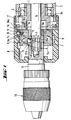
- the drilling and chiseling device with the front area shown in FIG. 1 has a guide sleeve 1.
- This guide sleeve 1 is rotatably supported by two ball bearings 2 in a device housing 3.
- the stop shoulder for one of the ball bearings 2 in the device housing 3 is formed by a locking ring 3a.
- a pneumatic percussion mechanism with percussion piston which is known per se and is therefore not shown in the drawing, is arranged in the rear region of the guide sleeve 1.
- an anvil 4 is slidably mounted in the front area of the guide sleeve 1.
- This striker 4 has toothing 4a which transmits rotation and torque.
- a circumferential groove 5 is arranged on the die 4.
- the profile of the groove 5 is preferably semicircular and corresponds to that Profile of the locking element 6, which is a ball in this embodiment.
- a tool holder 10 specially designed for pure rotary movement has a recess 11a in the rear area.
- an internal toothing which is complementary to the toothing 4a of the striker 4.
- the unlocked locking element 6 is located in the central region of the recess of the tool holder shaft 11. This can be a plurality of locking elements 6.
- An arrangement is preferably to be made in which three locking elements 6 are each arranged at an angle of 120 ° in the peripheral region of the tool holder shaft 11.
- the guide of the locking element 6 consists of a radial bore 11b in which the ball can be moved in the radial direction.
- This bore 11b is arranged in the rear region of the tool holder shaft 11.
- the diameter of the ball exceeds the wall thickness of the tool holder shaft 11 in the area of the rear recess 11a.
- the switching element 7 has control means 7b with which the locking element 6 can be radially engaged or disengaged from the locking element 6. Since an arrangement of a plurality of locking elements 6 in the circumferential direction is possible, a plurality of locking elements 6 can also be controlled by the switching element 7.
- the switching element 7 can be controlled from the outside by the actuating element 8.
- the shape of the switching element 7 is essentially cylindrical and essentially axially displaceable within the actuating means 8. At least one cam 7a is arranged in the peripheral region of the switching element 7.
- the actuating element 8 has helical grooves 9 on its inside, which have an essentially rectangular cross section. According to this cross section the cams 7a are complementary and engage in helical grooves 9. At the beginning and at the end of these grooves 9, an area 9a extends without an incline. This area 9a forms a self-locking against rotation of the actuating means 8 with respect to the switching element 7 under axial load.
- the striker 4 is brought into an ineffective position and locked there.
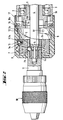
- FIG. 2 shows the locking element 6, which is inserted into the circumferential groove 5 of the striker 4.
- the switching element 7 is axially displaced by rotating the actuating means 8. Since the switching element 7 is connected to the tool holder shaft 11 and the die 4 via the locking element 6, all of these parts move axially when the actuating means 8 is rotated.
- the striker 4 is pulled into the non-impact end position and held there. This means that machining can be carried out with the drilling and chiseling device, in which a pure rotary movement is necessary.
- the switching element 7 is located at the rear end of the actuating means 8.
- the locking element 6 in the form of a ball is unlocked.
- the tool holder shaft 11 is pushed onto the front part of the striker 4, so that the two toothings 4a, 11a interlock.
- an intermediate disk 16 is arranged in an enlarged circumferential recess 17, which is fixed in the recess 17 with retaining rings 16a.
- the washer 16 has a stop collar 16b, which is supported on the end face 1a of the guide sleeve 1.
- the switching element 7 rotates with the actuating means 8.
- the position of the switching element 7 which is achieved in this way corresponds at the same time to the locking position of the locking element 6.
- a recess 12 is arranged on the helical groove base, into which a rotation-preventing element 13 of the switching element 7 can be inserted.
- the anti-rotation element 13 is a spring-loaded ball, which is arranged in a recess 14 in the cam 7a of the switching element 7.
- the recess 14 is arranged in the radial direction. The ball is guided in this recess 14 and presses on a spring 15 which is located within the recess 14 and is supported on the base of the recess 14.
- the striker 4 is locked in the end position, which has no impact on the stroke.
- the generated by the drive rotary movement transmitted by the striker 4 is transmitted from the striker 4 via the tool holder shaft 11 to a tool clamped in the tool holder 10.
- the striker 4 is unlocked in the reverse order to that described above.
Abstract
Description
Die Erfindung betrifft ein handgeführtes Bohr- und Meisselgerät mit Schlagwerk und Werkzeughalter, wobei das Schlagwerk über einen Döpper axiale Schläge auf ein im Werkzeughalter eingespanntes Werkzeug abgibt und der Döpper wenigstens eine Ausnehmung aufweist, in die ein Verriegelungselement durch ein Schaltorgan, das von aussen mittels eines Betätigungsmittels steuerbar ist, einrückbar ist.The invention relates to a hand-held drilling and chiseling device with striking mechanism and tool holder, the striking mechanism emitting axial strikes via a striker onto a tool clamped in the tool holder and the striker having at least one recess into which a locking element is inserted by a switching element which is actuated from the outside by means of a Actuator is controllable, can be engaged.
Bei einem aus der DE-PS 3 627 869 bekannten Bohrhammer mit pneumatischem Schlagwerk wird eine Schlagabschaltung mittels hakenförmiger Elemente, die in eine Ausnehmung des Schlägers einrückbar sind, erreicht. Der Schläger wird somit in schlagunwirksamer Endposition gehalten, so dass dieser keine axialen Schläge mehr auf das Werkzeug abgeben kann.In a hammer drill with a pneumatic hammer mechanism known from DE-PS 3 627 869, a hammer shut-off is achieved by means of hook-shaped elements which can be inserted into a recess in the racket. The racket is thus held in an ineffective end position so that it can no longer deliver axial blows to the tool.
Diese hakenförmigen Elemente sind in radialer Richtung bewegbar. Ein von aussen bedienbares Betätigungsmittel weist in einem inneren Umfangsbereich eine exzentrische Verformung in radialer Richtung auf, über die der Axialhub eines stiftförmigen Elementes steuerbar ist. Somit kann durch Verdrehen des Betätigungsmittels in Umfangsrichtung eine Axialbewegung des stiftförmigen Elementes erreicht werden, wobei das stiftförmige Element die radiale Bewegung des hakenförmigen Elementes steuert.These hook-shaped elements can be moved in the radial direction. An actuating means that can be operated from the outside has an eccentric deformation in the radial direction in an inner circumferential region, via which the axial stroke of a pin-shaped element can be controlled. Thus, by rotating the actuating means in the circumferential direction, an axial movement of the pin-shaped element can be achieved, the pin-shaped element controlling the radial movement of the hook-shaped element.
Da der Schläger nur in vorderster Position verriegelt werden kann, muss er so ausgebildet sein, dass dieser die mit Federkraft in radialer Richtung beaufschlagten hakenförmigen Elemente über eine schiefe Ebene radial auseinanderdrücken kann, so dass diese in eine an die schiefe Ebene anschliessende Ausnehmung des Schlägers hineinspringen können. Eine Verriegelung des Schlägers ist somit nur möglich, wenn der Schläger vom Schlagwerk in Bearbeitungsrichtung bewegt wird.Since the racket can only be locked in the foremost position, it must be designed in such a way that it can radially push apart the hook-shaped elements which are subjected to spring force in the radial direction over an inclined plane, so that they jump into a recess in the racket which adjoins the inclined plane can. Locking the racket is therefore only possible if the racket is moved in the machining direction by the striking mechanism.
Der Erfindung liegt die Aufgabe zugrunde, eine Verriegelungseinrichtung zu schaffen, durch die der Döpper in schlagunwirksame Position verschoben werden kann, ohne dass eine Inbetriebnahme des Gerätes zu erfolgen braucht.The invention has for its object to provide a locking device through which the striker in impact-resistant Position can be shifted without having to commission the device.
Erfindungsgemäss wird die Aufgabe dadurch gelöst, dass das Betätigungsmittel wenigstens eine Steuerkurve aufweist, die auf der Innenseite des Betätigungsmittels angeordnet ist und zur Erzeugung einer Axialbewegung des Schaltorgans dient.According to the invention, the object is achieved in that the actuating means has at least one control cam which is arranged on the inside of the actuating means and serves to generate an axial movement of the switching element.
Beim Bedienen des Betätigungsmittels erfolgt eine Axialbewegung des Schaltorgans innerhalb des Betätigungsmittels. Dadurch wird der über das Verriegelungselement mit dem Schaltorgan verbundene Döpper in die schlagunwirksame Position verschoben. Damit kann diese Position des Döppers von der Bedienungsperson ausschliesslich durch Handhabung des Betätigungsmittels erzielt werden, ohne dass das Gerät in Betrieb genommen werden muss.When the actuating means are operated, the switching member moves axially within the actuating means. As a result, the striker connected to the switching element via the locking element is displaced into the ineffective position. This position of the striker can thus only be achieved by the operator by handling the actuating means, without the device having to be put into operation.
Mittels der Steuerkurve werden die Bewegungen des Betätigungselementes auf das Schaltorgan übertragen.The movements of the actuating element are transmitted to the switching element by means of the control cam.
Vorzugsweise ist die Steuerkurve eine wendelförmige Nut. Durch Verdrehen des Betätigungselementes in Umfangsrichtung kann dadurch eine Axialbewegung des Schaltorgans errreicht werden. Das Verhältnis der Axialbewegung des Schaltorgans zum Verdrehungswinkel des Betätigungsmittels kann über die Steigung der wendelförmigen Nut bestimmt werden.The control curve is preferably a helical groove. By rotating the actuating element in the circumferential direction, an axial movement of the switching element can be achieved. The ratio of the axial movement of the switching element to the angle of rotation of the actuating means can be determined via the pitch of the helical groove.
Ein weiterer Vorteil der Erfindung liegt darin, dass in die wendelförmige Nut Teile des Schaltorgans eingreifen. Damit wird die Führung und die exakte Bewegung des Schaltorgans im Betätigungsmittel erreicht.Another advantage of the invention is that parts of the switching element engage in the helical groove. The guidance and the exact movement of the switching element in the actuating means are thus achieved.
Zweckmässigerweise sind die Teile des Schaltorgans im Umfangsbereich des Schaltorgans angeordnete Nocken. Diese Nocken entsprechen in ihrer Form vorzugsweise dem Querschnitt und der Steigung der wendelförmigen Nut. Durch ihre Anordnung im Umfangsbereich ist deren Herstellung einfach und wirtschaftlich.The parts of the switching element are expediently arranged cams in the peripheral region of the switching element. The shape of these cams preferably corresponds to the cross section and the slope of the helical groove. Through her Arrangement in the peripheral area is simple and economical to manufacture.
Die Erfindung eignet sich besonders für ein Bohr- und Meisselgerät mit einem abnehmbaren Werkzeughalter. Ein Umschalten bzw. Abschalten des Schlagbetriebes an der Maschine entfällt. Speziell bei gleichen Arbeiten, die sich über eine längere Zeitdauer erstrecken, ist es von Vorteil, wenn nicht immer darauf geachtet werden muss, ob die richtige Einstellung der Maschine erfolgt ist.The invention is particularly suitable for a drilling and chiseling device with a removable tool holder. Switching or switching off the field operation on the machine is not necessary. Especially when doing the same work, which extends over a longer period of time, it is advantageous if it is not always necessary to pay attention to whether the correct setting of the machine has been made.
Die Erfindung wird anhand eines Ausführungsbeispieles näher erläutert. Es zeigen
- Fig. 1
- eine teilweise geschnittene Darstellung des vorderen Geräteteiles mit dem Werkzeughalter in entriegelter Stellung;
- Fig. 2
- eine teilweise geschnittene Darstellung des vorderen Geräteteiles mit Werkzeughalter in verriegelter Stellung.
- Fig. 1
- a partially sectioned view of the front part of the device with the tool holder in the unlocked position;
- Fig. 2
- a partially sectioned view of the front part of the device with tool holder in the locked position.
Das Bohr- und Meisselgerät mit dem in Fig. 1 dargestellten Vorderbereich verfügt über eine Führungshülse 1. Diese Führungshülse 1 ist mit zwei Kugellagern 2 in einem Gerätegehäuse 3 drehgelagert. Die Anschlagschulter für eines der Kugellager 2 im Gerätegehäuse 3 wird von einem Sicherungsring 3a gebildet. Im hinteren Bereich der Führungshülse 1 ist ein an sich bekanntes und daher zeichnerisch nicht dargestelltes pneumatisches Schlagwerk mit Schlagkolben angeordnet.The drilling and chiseling device with the front area shown in FIG. 1 has a guide sleeve 1. This guide sleeve 1 is rotatably supported by two
Im vorderen Bereich der Führungshülse 1 ist ein Döpper 4 verschiebbar gelagert. Dieser Döpper 4 weist eine Drehmitnahme und Drehmoment übertragende Verzahnung 4a auf. Im Endbereich der Verzahnung 4a in rückwärtiger Richtung ist am Döpper 4 eine umlaufende Nut 5 angeordnet. Das Profil der Nut 5 ist vorzugsweise halbkreisförmig und entspricht dem Profil des Verriegelungselementes 6, das in diesem Ausführungsbeispiel eine Kugel ist.In the front area of the guide sleeve 1, an
Ein speziell für reine Drehbewegung ausgelegter Werkzeughalter 10 weist eine Ausnehmung 11a im rückwärtigen Bereich auf. In der Ausnehmung 11a ist eine komplementär zur Verzahnung 4a des Döppers 4 ausgebildete Innenverzahnung angeordnet. Im mittleren Bereich der Ausnehmung des Werkzeughalterschaftes 11 befindet sich das entriegelte Verriegelungselement 6. Es kann sich dabei um mehrere Verriegelungselemente 6 handeln. Vorzugsweise ist eine Anordnung zu treffen, bei der im Umfangsbereich des Werkzeughalterschaftes 11 drei Verriegelungselemente 6 jeweils unter einem Winkel von 120° angeordnet sind.A
Die Führung des Verriegelungselementes 6 besteht aus einer radialen Bohrung 11b, in der die Kugel in radialer Richtung bewegt werden kann. Diese Bohrung 11b ist im rückwärtigen Bereich des Werkzeughalterschaftes 11 angeordnet. Der Durchmesser der Kugel übersteigt die Wandstärke des Werkzeughalterschaftes 11 im Bereich der rückwärtigen Ausnehmung 11a. Das Schaltorgan 7 weist Steuermittel 7b auf, mit der das Verriegelungselement 6 radial eingerückt werden kann bzw. ein Ausrücken des Verriegelungselementes 6 ermöglicht. Da eine Anordnung mehrerer Verriegelungselemente 6 in Umfangsrichtung möglich ist, können auch mehrere Verriegelungselemente 6 vom Schaltorgan 7 gesteuert werden. Das Schaltorgan 7 ist durch das Betätigungselement 8 von aussen steuerbar.The guide of the
Die Form des Schaltorgans 7 ist im wesentlichen zylindrisch und innerhalb des Betätigungsmittels 8 im wesentlichen axial verschiebbar. Im Umfangsbereich des Schaltorgans 7 ist wenigstens ein Nocken 7a angeordnet.The shape of the
Das Betätigungselement 8 weist an seiner Innenseite wendelförmige Nuten 9 auf, die einen im wesentlichen rechteckigen Querschnitt aufweisen. Entsprechend diesem Querschnitt sind die Nocken 7a komplementär ausgebildet und greifen in wendelförmige Nuten 9 ein. Jeweils am Anfang und am Ende dieser Nuten 9 erstreckt sich ein Bereich 9a, der ohne Steigung ausgebildet ist. Dieser Bereich 9a bildet eine Selbsthemmung gegen Verdrehung des Betätigungsmittels 8 gegenüber dem Schaltorgan 7 bei axialer Belastung.The actuating
Um eine reine Drehbewegung des Bohrwerkzeuges erreichen zu können, wird der Döpper 4 in eine schlagunwirksame Position gebracht und dort verriegelt.In order to be able to achieve a pure rotary movement of the drilling tool, the
Am rückwärtigen Ende des Werkzeughalterschaftes 11 sind im Umfangsbereich zwei nicht dargestellte Ausnehmungen vorhanden, in die ein Stellelement einrückbar ist. Mittels diesem Stellelement wird das Betätigungsmittel 8 in der Verriegelungs- bzw. Entriegelungsstellung gehalten.At the rear end of the
Die Figur 2 zeigt das Verriegelungselement 6, das in die umlaufende Nut 5 des Döppers 4 eingerückt ist. Durch das Verdrehen des Betätigungsmittels 8 wird das Schaltorgan 7 axial verschoben. Da das Schaltorgan 7 über das Verriegelungselement 6 mit dem Werkzeughalterschaft 11 und dem Döpper 4 verbunden ist, erfolgt bei der Verdrehung des Betätigungsmittels 8 eine Axialbewegung aller dieser Teile. Der Döpper 4 wird in schlagunwirksame Endposition gezogen und dort festgehalten. Somit kann mit dem Bohr- und Meisselgerät eine Bearbeitung durchgeführt werden, bei der eine reine Drehbewegung notwendig ist.FIG. 2 shows the
In der Grundstellung befindet sich das Schaltorgan 7 am rückwärtigen Ende des Betätigungsmittels 8. Das Verriegelungselement 6 in Form einer Kugel ist entriegelt. Nunmehr wird der Werkzeughalterschaft 11 auf den vorderen Teil des Döppers 4 aufgesteckt, so dass beide Verzahnungen 4a, 11a ineinandergreifen. Im rückwärtigen Bereich des Betätigungselementes 8 ist in einer erweiterten umlaufenden Ausnehmung 17 eine Zwischenscheibe 16 angeordnet, die mit Sicherungsringen 16a in der Ausnehmung 17 fixiert ist. Die Zwischenscheibe 16 weist einen Anschlagbund 16b auf, der sich an der Stirnseite 1a der Führungshülse 1 abstützt.In the basic position, the switching
Durch ein erstmaliges Verdrehen des Betätigungsmittels 8 in Umfangsrichtung dreht sich das Schaltorgan 7 mit dem Betätigungsmittel 8. Die dabei erreichte Stellung des Schaltorgans 7 entspricht gleichzeitig der Verriegelungsstellung des Verriegelungselementes 6. Das Verriegelungselement 6, ebenfalls in Form einer Kugel, greift in eine umlaufend ausgebildete Ausnehmung 5 am Döpper 4 ein.When the actuating means 8 is rotated for the first time in the circumferential direction, the switching
In dem ohne Steigung verlaufenden Anfangsbereich der wendelförmigen Nut 9 ist am wendelförmigen Nutengrund eine Ausnehmung 12 angeordnet, in die ein Verdrehsicherungselement 13 des Schaltorganes 7 einrückbar ist. Das Verdrehsicherungselement 13 ist eine durch Federkraft beaufschlagte Kugel, die in einer Ausnehmung 14 im Nocken 7a des Schaltorgans 7 angeordnet ist. Die Ausnehmung 14 ist in radialer Richtung angeordnet. Die Kugel wird in dieser Ausnehmung 14 geführt und drückt auf eine Feder 15, die sich innerhalb der Ausnehmung 14 befindet und sich am Grund der Ausnehmung 14 abstützt. Durch eine weitere Verdrehung des Betätigungsmittels 8 wird die Kugel aus der Ausnehmung 12 am Grund der wendelförmigen Nut 9 ausgerückt und in die am Nocken angeordnete Ausnehmung 14 eingedrückt.In the initial region of the
Bei weiterem Verdrehen des Betätigungsmittels 8 verlässt der Nocken 7a den ohne Steigung ausgebildeten Bereich 9a der Nut 9 und gelangt in den wendelförmig ausgestalteten Bereich. Dabei erfolgt eine Relativbewegung des Schaltorgans 7 in axialer Richtung gegenüber dem Betätigungsmittel 8.When the actuating means 8 is rotated further, the
Am Ende des wendelförmigen Bereiches befindet sich wiederum ein ohne Steigung verlaufender Teil 9a der Nut 9, der wiederum eine Selbsthemmung auf Verdrehen des Betätigungsmittels 8 gewährleisten soll.At the end of the helical area there is again a
Ist diese Position erreicht, so ist der Döpper 4 in schlagunwirksamer Endposition verriegelt. Die vom Antrieb erzeugte, durch den Döpper 4 übertragene Drehbewegung überträgt sich vom Döpper 4 über den Werkzeughalterschaft 11 auf ein im Werkzeughalter 10 eingespanntes Werkzeug.If this position is reached, the
Die Entriegelung des Döppers 4 erfolgt in umgekehrter Reihenfolge, wie zuvor beschrieben wurde.The
Claims (4)
- Manually guided drilling and chiseling tool comprising a percussion mechanism and tool chuck (10̸), wherein the percussion mechanism emits axial percussions via an anvil (4) to a tool which is clamped in the tool chuck (10̸) and the anvil (4) has at least one cut-out into which a locking element (6) is engaged by means of a control element (7) which is externally controlled by means of an operating means (8), characterised in that the operating means (8) has at least one control curve, which is arranged on the inside of the operating means (8) and which serves to produce an axial movement of the control element (7).
- Tool according to claim 1, characterised in that the control curve is a helical groove (9).
- Tool according to claim 2, characterised in that parts of the control element (7) engage the helical groove (9).
- Tool according to claim 3, characterised in that the parts of the control element (7) are cams (7a) arranged in the peripheral area of the control element (7).
Applications Claiming Priority (2)
| Application Number | Priority Date | Filing Date | Title |
|---|---|---|---|
| DE4038395 | 1990-12-01 | ||
| DE4038395A DE4038395A1 (en) | 1990-12-01 | 1990-12-01 | DRILL AND CHISEL |
Publications (2)
| Publication Number | Publication Date |
|---|---|
| EP0489687A1 EP0489687A1 (en) | 1992-06-10 |
| EP0489687B1 true EP0489687B1 (en) | 1993-07-14 |
Family
ID=6419398
Family Applications (1)
| Application Number | Title | Priority Date | Filing Date |
|---|---|---|---|
| EP91810904A Expired - Lifetime EP0489687B1 (en) | 1990-12-01 | 1991-11-20 | Drilling and chiseling tool |
Country Status (10)
| Country | Link |
|---|---|
| EP (1) | EP0489687B1 (en) |
| JP (1) | JPH04269107A (en) |
| AT (1) | ATE91452T1 (en) |
| AU (1) | AU640541B2 (en) |
| CA (1) | CA2056545A1 (en) |
| DE (2) | DE4038395A1 (en) |
| DK (1) | DK0489687T3 (en) |
| ES (1) | ES2041554T3 (en) |
| FI (1) | FI915604A (en) |
| HU (1) | HUT60180A (en) |
Families Citing this family (3)
| Publication number | Priority date | Publication date | Assignee | Title |
|---|---|---|---|---|
| DE4136584B4 (en) * | 1991-11-07 | 2004-10-28 | Hilti Ag | Drilling and chiseling device with tool holder |
| JP4552843B2 (en) * | 2005-12-09 | 2010-09-29 | パナソニック電工株式会社 | Hammer tool adapter |
| DE102005059182A1 (en) * | 2005-12-12 | 2007-06-14 | Robert Bosch Gmbh | Operating mode selector switch for setting at least one operating mode in a handheld power tool |
Family Cites Families (3)
| Publication number | Priority date | Publication date | Assignee | Title |
|---|---|---|---|---|
| GB1195505A (en) * | 1967-07-31 | 1970-06-17 | Hilti Ag | Hammer Drill |
| JPS5930607A (en) * | 1982-08-12 | 1984-02-18 | Hitachi Koki Co Ltd | Electric hammer drill |
| DE3627869A1 (en) * | 1986-08-16 | 1988-02-18 | Bosch Gmbh Robert | DRIVE SHUTDOWN |
-
1990
- 1990-12-01 DE DE4038395A patent/DE4038395A1/en not_active Withdrawn
-
1991
- 1991-11-20 DE DE9191810904T patent/DE59100191D1/en not_active Expired - Fee Related
- 1991-11-20 ES ES199191810904T patent/ES2041554T3/en not_active Expired - Lifetime
- 1991-11-20 DK DK91810904.2T patent/DK0489687T3/en active
- 1991-11-20 EP EP91810904A patent/EP0489687B1/en not_active Expired - Lifetime
- 1991-11-20 AT AT91810904T patent/ATE91452T1/en not_active IP Right Cessation
- 1991-11-28 CA CA002056545A patent/CA2056545A1/en not_active Abandoned
- 1991-11-28 FI FI915604A patent/FI915604A/en not_active Application Discontinuation
- 1991-11-29 HU HU913736A patent/HUT60180A/en unknown
- 1991-11-29 AU AU88317/91A patent/AU640541B2/en not_active Ceased
- 1991-12-02 JP JP3318049A patent/JPH04269107A/en active Pending
Also Published As
| Publication number | Publication date |
|---|---|
| CA2056545A1 (en) | 1992-06-02 |
| HUT60180A (en) | 1992-08-28 |
| JPH04269107A (en) | 1992-09-25 |
| FI915604A (en) | 1992-06-02 |
| AU640541B2 (en) | 1993-08-26 |
| HU913736D0 (en) | 1992-03-30 |
| FI915604A0 (en) | 1991-11-28 |
| DK0489687T3 (en) | 1993-11-29 |
| EP0489687A1 (en) | 1992-06-10 |
| ES2041554T3 (en) | 1993-11-16 |
| ATE91452T1 (en) | 1993-07-15 |
| DE4038395A1 (en) | 1992-06-04 |
| AU8831791A (en) | 1992-06-04 |
| DE59100191D1 (en) | 1993-08-19 |
Similar Documents
| Publication | Publication Date | Title |
|---|---|---|
| EP0221009B1 (en) | Drill hammer with rotation interruption | |
| EP0494400B1 (en) | Hand-tool with removable tool-holder | |
| DE19821554B4 (en) | Drill with impact mechanism | |
| EP1326736B1 (en) | Tool mounting for a hand machine tool | |
| DE3932660C2 (en) | Impact drill with mechanical impact transmission | |
| CH655273A5 (en) | TOOL HOLDER FOR DRILLING AND IMPACT DRILLING DEVICES. | |
| EP0108411A1 (en) | Drilling machine | |
| DE102005036731A1 (en) | Coupling device for a power tool and power tool | |
| DE10105250A1 (en) | Tool insert holding device in striking tools | |
| EP0618031A2 (en) | Hand-held drilling machine and its tool holder | |
| DE1948055A1 (en) | Electrically operated rotary hammer | |
| CH663557A5 (en) | DRILL CHUCK FOR IMPACT DRILLING. | |
| EP0548008A1 (en) | Tool for impact drilling and chiseling and tool chuck therefor | |
| DE3516541A1 (en) | Tool holder | |
| EP0489687B1 (en) | Drilling and chiseling tool | |
| EP1409207A2 (en) | Tool holder for a hand tool | |
| DE3405102C2 (en) | ||
| DE3804414A1 (en) | Hammer drill with ball catch clutch | |
| DE4445598C2 (en) | Hand-held machine tool | |
| DE2806611A1 (en) | Operation mode switch for electropneumatic hammer drill - has recess for additional locking unit detent action for rotary or percussive setting | |
| EP0375917B1 (en) | Drilling machine | |
| EP0768150A1 (en) | Tool holder | |
| DE3227707A1 (en) | Percussion drill | |
| DE3333856A1 (en) | Device for switching over an electropneumatic hammer drill from rotary drilling to hammer drilling and vice versa | |
| DE2408557A1 (en) | DEVICE FOR TRANSMISSION OF TORQUE TO PREFERRED IMPACT DRILLING TOOLS |
Legal Events
| Date | Code | Title | Description |
|---|---|---|---|
| PUAI | Public reference made under article 153(3) epc to a published international application that has entered the european phase |
Free format text: ORIGINAL CODE: 0009012 |
|
| AK | Designated contracting states |
Kind code of ref document: A1 Designated state(s): AT BE CH DE DK ES FR GB IT LI NL SE |
|
| 17P | Request for examination filed |
Effective date: 19920627 |
|
| 17Q | First examination report despatched |
Effective date: 19921125 |
|
| GRAA | (expected) grant |
Free format text: ORIGINAL CODE: 0009210 |
|
| AK | Designated contracting states |
Kind code of ref document: B1 Designated state(s): AT BE CH DE DK ES FR GB IT LI NL SE |
|
| REF | Corresponds to: |
Ref document number: 91452 Country of ref document: AT Date of ref document: 19930715 Kind code of ref document: T |
|
| ITF | It: translation for a ep patent filed |
Owner name: BARZANO' E ZANARDO MILANO S.P.A. |
|
| ET | Fr: translation filed | ||
| REF | Corresponds to: |
Ref document number: 59100191 Country of ref document: DE Date of ref document: 19930819 |
|
| REG | Reference to a national code |
Ref country code: ES Ref legal event code: FG2A Ref document number: 2041554 Country of ref document: ES Kind code of ref document: T3 |
|
| REG | Reference to a national code |
Ref country code: DK Ref legal event code: T3 |
|
| GBT | Gb: translation of ep patent filed (gb section 77(6)(a)/1977) |
Effective date: 19931125 |
|
| PLBE | No opposition filed within time limit |
Free format text: ORIGINAL CODE: 0009261 |
|
| STAA | Information on the status of an ep patent application or granted ep patent |
Free format text: STATUS: NO OPPOSITION FILED WITHIN TIME LIMIT |
|
| 26N | No opposition filed | ||
| PGFP | Annual fee paid to national office [announced via postgrant information from national office to epo] |
Ref country code: FR Payment date: 19941028 Year of fee payment: 4 |
|
| PGFP | Annual fee paid to national office [announced via postgrant information from national office to epo] |
Ref country code: AT Payment date: 19941107 Year of fee payment: 4 |
|
| PGFP | Annual fee paid to national office [announced via postgrant information from national office to epo] |
Ref country code: BE Payment date: 19941116 Year of fee payment: 4 |
|
| PGFP | Annual fee paid to national office [announced via postgrant information from national office to epo] |
Ref country code: ES Payment date: 19941121 Year of fee payment: 4 |
|
| PGFP | Annual fee paid to national office [announced via postgrant information from national office to epo] |
Ref country code: DK Payment date: 19941129 Year of fee payment: 4 |
|
| PGFP | Annual fee paid to national office [announced via postgrant information from national office to epo] |
Ref country code: NL Payment date: 19941130 Year of fee payment: 4 |
|
| EAL | Se: european patent in force in sweden |
Ref document number: 91810904.2 |
|
| PGFP | Annual fee paid to national office [announced via postgrant information from national office to epo] |
Ref country code: CH Payment date: 19950221 Year of fee payment: 4 |
|
| PG25 | Lapsed in a contracting state [announced via postgrant information from national office to epo] |
Ref country code: DK Effective date: 19951120 Ref country code: AT Effective date: 19951120 Ref country code: GB Effective date: 19951120 |
|
| REG | Reference to a national code |
Ref country code: DK Ref legal event code: EBP |
|
| PG25 | Lapsed in a contracting state [announced via postgrant information from national office to epo] |
Ref country code: ES Free format text: LAPSE BECAUSE OF THE APPLICANT RENOUNCES Effective date: 19951121 |
|
| PG25 | Lapsed in a contracting state [announced via postgrant information from national office to epo] |
Ref country code: CH Effective date: 19951130 Ref country code: BE Effective date: 19951130 Ref country code: LI Effective date: 19951130 |
|
| BERE | Be: lapsed |
Owner name: HILTI A.G. Effective date: 19951130 |
|
| PG25 | Lapsed in a contracting state [announced via postgrant information from national office to epo] |
Ref country code: NL Effective date: 19960601 |
|
| REG | Reference to a national code |
Ref country code: CH Ref legal event code: PL |
|
| GBPC | Gb: european patent ceased through non-payment of renewal fee |
Effective date: 19951120 |
|
| PG25 | Lapsed in a contracting state [announced via postgrant information from national office to epo] |
Ref country code: FR Effective date: 19960731 |
|
| NLV4 | Nl: lapsed or anulled due to non-payment of the annual fee |
Effective date: 19960601 |
|
| REG | Reference to a national code |
Ref country code: FR Ref legal event code: ST |
|
| PGFP | Annual fee paid to national office [announced via postgrant information from national office to epo] |
Ref country code: SE Payment date: 19990812 Year of fee payment: 9 |
|
| PG25 | Lapsed in a contracting state [announced via postgrant information from national office to epo] |
Ref country code: SE Free format text: THE PATENT HAS BEEN ANNULLED BY A DECISION OF A NATIONAL AUTHORITY Effective date: 20001129 |
|
| REG | Reference to a national code |
Ref country code: ES Ref legal event code: FD2A Effective date: 20010402 |
|
| EUG | Se: european patent has lapsed |
Ref document number: 91810904.2 |
|
| PG25 | Lapsed in a contracting state [announced via postgrant information from national office to epo] |
Ref country code: IT Free format text: LAPSE BECAUSE OF NON-PAYMENT OF DUE FEES;WARNING: LAPSES OF ITALIAN PATENTS WITH EFFECTIVE DATE BEFORE 2007 MAY HAVE OCCURRED AT ANY TIME BEFORE 2007. THE CORRECT EFFECTIVE DATE MAY BE DIFFERENT FROM THE ONE RECORDED. Effective date: 20051120 |
|
| PGFP | Annual fee paid to national office [announced via postgrant information from national office to epo] |
Ref country code: DE Payment date: 20081027 Year of fee payment: 18 |
|
| PG25 | Lapsed in a contracting state [announced via postgrant information from national office to epo] |
Ref country code: DE Free format text: LAPSE BECAUSE OF NON-PAYMENT OF DUE FEES Effective date: 20100601 |