EP0489382B1 - An einer Wand befestigter Haartrockner - Google Patents
An einer Wand befestigter Haartrockner Download PDFInfo
- Publication number
- EP0489382B1 EP0489382B1 EP91120659A EP91120659A EP0489382B1 EP 0489382 B1 EP0489382 B1 EP 0489382B1 EP 91120659 A EP91120659 A EP 91120659A EP 91120659 A EP91120659 A EP 91120659A EP 0489382 B1 EP0489382 B1 EP 0489382B1
- Authority
- EP
- European Patent Office
- Prior art keywords
- switch
- nozzle
- connector
- hot air
- hair drier
- Prior art date
- Legal status (The legal status is an assumption and is not a legal conclusion. Google has not performed a legal analysis and makes no representation as to the accuracy of the status listed.)
- Expired - Lifetime
Links
- 238000001035 drying Methods 0.000 claims description 11
- 238000007664 blowing Methods 0.000 claims description 2
- 230000000295 complement effect Effects 0.000 claims description 2
- 238000005192 partition Methods 0.000 claims description 2
- 230000002093 peripheral effect Effects 0.000 claims description 2
- 230000014759 maintenance of location Effects 0.000 claims 1
- 239000003570 air Substances 0.000 description 17
- 240000008042 Zea mays Species 0.000 description 1
- 239000012080 ambient air Substances 0.000 description 1
- 238000006073 displacement reaction Methods 0.000 description 1
- 230000007257 malfunction Effects 0.000 description 1
- 238000004519 manufacturing process Methods 0.000 description 1
Images
Classifications
-
- A—HUMAN NECESSITIES
- A45—HAND OR TRAVELLING ARTICLES
- A45D—HAIRDRESSING OR SHAVING EQUIPMENT; EQUIPMENT FOR COSMETICS OR COSMETIC TREATMENTS, e.g. FOR MANICURING OR PEDICURING
- A45D20/00—Hair drying devices; Accessories therefor
- A45D20/04—Hot-air producers
- A45D20/08—Hot-air producers heated electrically
- A45D20/16—Fixed installed drying devices
-
- A—HUMAN NECESSITIES
- A45—HAND OR TRAVELLING ARTICLES
- A45D—HAIRDRESSING OR SHAVING EQUIPMENT; EQUIPMENT FOR COSMETICS OR COSMETIC TREATMENTS, e.g. FOR MANICURING OR PEDICURING
- A45D20/00—Hair drying devices; Accessories therefor
- A45D20/04—Hot-air producers
- A45D20/08—Hot-air producers heated electrically
- A45D20/10—Hand-held drying devices, e.g. air douches
Definitions
- the invention relates to hair dryers comprising a housing, a region of which comprises means for fixing to a vertical wall such as for example a wall, and which contains a group of hot air generators with a fan motor controlled by an electric switch. and intended to establish a current of air between an air inlet orifice and a hot air outlet orifice.
- the hot air outlet orifice receives a connector secured to a flexible tube equipped with a hair drying nozzle which can be brought either to a storage position. or rest for which the switch is in an open state, or in a position of use for which the switch is in a closed state and allows drying of the hair
- the electrical switch is generally mounted in a housing of the housing and is controlled directly by the nozzle when it comes off the housing and vice versa. This type of command proves dangerous because if the user forgets to hang up or if the hook takes place inadvertently, the generator group operates continuously and may catch fire in certain cases, for example, when the motor-driven fan malfunctions.
- the object of the present invention is in particular to eliminate these drawbacks.
- the connector is mounted so as to be able to rotate on said hot air outlet orifice, and comprises a means for actuating the switch such that the passage of the drying nozzle from its storage or rest position. in its position of use, by transmitting the movement of said nozzle to the connector by means of the flexible tube, the switch in its closed state and vice versa.
- the pivoting of the connector is subordinate to the spatial position of the nozzle and automatically causes the switch to be placed in the open state when the nozzle is brought into the storage or rest position.
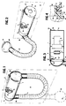
- the hair dryer shown comprises a housing 1 having the general shape of a cylinder whose end partitions 1a-1b are open and one region of its lateral surface has a boss 2 carrying removable fixing means on a vertical wall P such as, for example, a wall so as to maintain said cylinder in a practically horizontal position and parallel to said vertical wall.
- the fixing means (not shown) can be buttonholes adapted to hang on hooks fixed to the wall.
- the box 1 contains a hot air generator group with a motor-fan 3 and of the type with a wound electrical resistance 4.
- Said group 3-4 is controlled by an electric switch 5 and is intended to establish a current of air between the connections end 1a-1b which respectively have the ambient air inlet 6 and hot air outlet 7 holes.
- the hot air outlet 7 receives a connector 8 secured to a flexible tube 9 equipped a hair drying nozzle 10 which can be brought either to a storage position (illustrated in solid lines in FIG. 1) or in a rest position (illustrated in broken lines in FIG. 1) for which the switch 5 is in an open state (turning off the hot air generator group), or in a position of use (Figure 2) for which the switch 5 is in a closed state (turning on the hot air generator group) , and allows hair drying.
- the blowing nozzle 10 and the wall 1b having the air inlet orifice 6 comprise mutual attachment means such as a hook 12 secured to the nozzle 10 and a support 13 secured to the wall 1b, the flexible tube 9 thus having in the storage position the shape of a U.
- the connector 8 is mounted so as to be able to rotate on the orifice 7 for the outlet of hot air, and comprises an actuating means 14 of the switch 5 such that the passage of the drying nozzle 10 from its position storage or rest (Figure 1) in its position of use ( Figure 2) brings, by transmitting the movement of said nozzle 10 to the connector 8 by means of the flexible tube 9, the switch 5 in its closed state and vice versa.
- the invention provides, as can be seen better in FIG. 4, that said orifice 7 forms, by its internal edge, a cylindrical bearing 16 to axis substantially horizontal and parallel to the vertical wall P , and the connector 8 has a crown 15 of complementary shape rotatably mounted on said bearing around said axis, the bearing 16 and the crown 15 comprising mutual retaining means constituted by the interlocking of the edge forming a bearing 16 in a U-shaped groove 17 formed in the crown 15.
- the connector 8 has the shape of an elbow, one end of which comprises the crown 15 which bears on its peripheral edge 15 'turned towards the switch the actuating means 14 of the switch 5, and the other end of which receives the flexible tube 9.
- the actuating means 14 of the switch 5 is constituted by a wing which extends in an arc of a circle concentric with the crown 15 and defined angularly with respect to the position of switch 5 in the housing.
- the nozzle 10 in its storage position (illustrated in solid lines in Figure 1).
- the user wishes to use the hairdryer, he unhooks the nozzle 10 from the wall 1b, then brings it, in the direction of his head, in its position of use.
- This movement away from the nozzle of the vertical wall P is accompanied by the displacement of the tube 9 whose end connected to the connector 8 causes a tilting torque causing the rotation of said connector on the bearing 16.
- This rotation of the connector causes l wing 14 from its position illustrated in FIG. 1 for which it maintains the switch 5 in its open position, in a position illustrated, for example, in FIG. 2 and for which it releases the switch 5 which automatically switches to its closed state thus supplying the hot air generator 3-4.
- the dimensioning and the angular position of the wing 4 with respect to the switch 5 are chosen so that the switch goes from its open state to its closed state as soon as the user moves the nozzle 10 away from the vertical wall P.
Landscapes
- Cleaning And Drying Hair (AREA)
- Hair Curling (AREA)
Claims (6)
- Haartrockner mit einem Gehäuse (1), von dem ein Bereich Mittel zur Befestigung an einer vertikalen Wand (P) wie beispielsweise einer Mauer aufweist, und die eine Heißluftgeneratoreinheit mit einem Lüftersatz (3-4) besitzt, die von einem elektrischen Schalter (5) gesteuert wird und dazu bestimmt ist, einen Luftstrom zwischen einer Lufteintrittsöffnung (6) und einer Heißluftaustrittsöffnung (7) herzustellen, die einen an einem flexiblen Schlauch (9) fest angebrachten Verbinder (8) aufnimmt, der mit einer Düse (10) zum Trocknen der Haare ausgestattet ist, die entweder in eine aufgeräumte oder Ruheposition, bei der sich der Schalter (5) im geöffneten Zustand befindet, oder in eine Verwendungsposition gebracht werden kann, bei der sich der Schalter (5) im geschlossenen Zustand befindet und das Trocknen der Haare ermöglicht,
dadurch gekennzeichnet, daß der Verbinder (8) drehbeweglich an der Heißluftaustrittsöffnung (7) angebracht ist und ein Element (14) zur Betätigung des Schalters (5) aufweist, so daß der Übergang der Trockendüse (10) aus ihrer aufgeräumten oder Ruheposition in ihre Verwendungsposition den Schalter (5) durch Übertragung der Bewegung der Düse (10) zu dem Verbinder (8) mittels des flexiblen Schlauchs (9) in den geschlossenen Zustand bringt und umgekehrt. - Haartrockner nach Anspruch 1,
dadurch gekennzeichnet, daß die Heißluftaustrittsöffnung (7) ein zylindrisches Lager (16) mit einer praktisch horizontalen und zu der vertikalen Wand (P) parallelen Achse aufweist und der Verbinder (8) einen Kranz (15) mit komplementärer Form besitzt, der um die Achse drehbar an dem Lager (16) angebracht ist, wobei das Lager (16) und der Kranz (15) Mittel zum gegenseitigen Halten aufweisen. - Haartrockner nach Anspruch 2,
dadurch gekennzeichnet, daß der Verbinder (8) die allgemeine Form eines Kniestücks aufweist, von dem ein Ende den Kranz (15) aufweist, der an seinem Umfangsrand (15') das Mittel (14) zur Betätigung des Schalters (5) trägt, und dessen anderes Ende (18) den flexiblen Schlauch (9) aufnimmt. - Haartrockner nach Anspruch 2 oder 3,
dadurch gekennzeichnet, daß das Mittel (14) zur Betätigung des Schalters (5) durch einen Flügel gebildet ist, der sich entlang eines Kreisbogens erstreckt, der zu dem Kranz (15) konzentrisch ist und bezüglich der Position des Schalters (5) in dem Gehäuse (1) winkelmäßig derart gebildet ist, daß er den geöffneten Zustand des Schalters nur dann sicherstellt, wenn die Düse (10) ihre aufgeräumte oder Ruheposition einnimmt. - Haartrockner nach einem der Ansprüche 2 bis 3,
dadurch gekennzeichnet, daß das Gehäuse (1) die allgemeine Form eines Zylinders besitzt, dessen Endwände (1a - 1b) geöffnet sind, um die Lufteintrittsöffnung (6) und die Luftaustrittsöffnung (7) zu bilden, und von dem ein Bereich seiner Seitenfläche eine Erhöhung (2) besitzt, die die Mittel zur Befestigung an der vertikalen Wand (P) derart trägt, daß der Zylinder an einer praktisch horizontalen und zu der vertikalen Wand parallelen Position gehalten wird. - Haartrockner nach Anspruch 5,
dadurch gekennzeichnet, daß die Blasdüse (10) und die Endwand (1b), die die Lufteintrittsöffnung (6) aufweist, Mittel zum gegenseitigen Einhaken (12 und 13) aufweisen, die es ermöglichen, die Düse (10) in ihrer aufgeräumten oder Ruheposition zu halten.
Applications Claiming Priority (2)
| Application Number | Priority Date | Filing Date | Title |
|---|---|---|---|
| FR9015312A FR2670093B1 (fr) | 1990-12-06 | 1990-12-06 | Seche-cheveux mural. |
| FR9015312 | 1990-12-06 |
Publications (3)
| Publication Number | Publication Date |
|---|---|
| EP0489382A2 EP0489382A2 (de) | 1992-06-10 |
| EP0489382A3 EP0489382A3 (en) | 1993-06-30 |
| EP0489382B1 true EP0489382B1 (de) | 1995-08-09 |
Family
ID=9402978
Family Applications (1)
| Application Number | Title | Priority Date | Filing Date |
|---|---|---|---|
| EP91120659A Expired - Lifetime EP0489382B1 (de) | 1990-12-06 | 1991-12-02 | An einer Wand befestigter Haartrockner |
Country Status (7)
| Country | Link |
|---|---|
| US (1) | US5181328A (de) |
| EP (1) | EP0489382B1 (de) |
| KR (1) | KR940006481B1 (de) |
| DE (1) | DE69111994T2 (de) |
| ES (1) | ES2076448T3 (de) |
| FR (1) | FR2670093B1 (de) |
| PT (1) | PT99693B (de) |
Families Citing this family (19)
| Publication number | Priority date | Publication date | Assignee | Title |
|---|---|---|---|---|
| US5568691A (en) * | 1992-09-22 | 1996-10-29 | Secajo, Ltd. | Hair dryer apparatus adapted for multi-functional usage |
| US5404419A (en) * | 1993-06-25 | 1995-04-04 | Artis, Jr.; Amos | Wall-mounted cordless dryer for the hands with battery charging circuit, AM/FM radio, and vertical positioning means |
| US5832624A (en) * | 1996-02-02 | 1998-11-10 | Narrin; Nancy | Device for providing elevated and universally adjustable support of a hair dryer |
| US5613305A (en) * | 1996-02-02 | 1997-03-25 | Narrin; Nancy | Device for providing elevated and universally adjustable support of a hair dryer |
| US5727331A (en) * | 1996-06-27 | 1998-03-17 | Windmere Corporation | Dual switch electric hair dryer |
| US5956862A (en) * | 1998-08-20 | 1999-09-28 | Bondi; Leonard J. | Multipositional support for a hair dryer |
| US6925729B2 (en) * | 2003-10-29 | 2005-08-09 | Hamilton Beach/Proctor-Silex, Inc. | Hair dryer and mounting assembly |
| FR2867956B1 (fr) * | 2004-03-25 | 2007-01-19 | Jvd Sas Soc Par Actions Simpli | Perfectionnement aux dispositifs seche-cheveux muraux |
| DE112008002455T5 (de) | 2007-09-20 | 2010-07-22 | Bradley Fixtures Corp., Menomonee Falls | Waschraumsystem |
| ITMN20090001U1 (it) * | 2009-03-25 | 2010-09-26 | Gianni Sani | Asciugacapelli con distanziatore |
| US8064756B2 (en) * | 2009-05-20 | 2011-11-22 | Hokwang Industries Co., Ltd. | Airflow directing structure for hand dryers |
| MX366199B (es) | 2009-10-07 | 2019-06-25 | Bradley Fixtures Corp | Sistema de lavabo con secador de manos. |
| US9170148B2 (en) | 2011-04-18 | 2015-10-27 | Bradley Fixtures Corporation | Soap dispenser having fluid level sensor |
| US9267736B2 (en) | 2011-04-18 | 2016-02-23 | Bradley Fixtures Corporation | Hand dryer with point of ingress dependent air delay and filter sensor |
| USD663016S1 (en) | 2011-08-25 | 2012-07-03 | Bradley Fixtures Corporation | Lavatory system with integrated hand dryer |
| MX352853B (es) | 2012-03-21 | 2017-12-13 | Bradley Fixtures Corp | Sistema de lavabo y secador de manos. |
| US10100501B2 (en) | 2012-08-24 | 2018-10-16 | Bradley Fixtures Corporation | Multi-purpose hand washing station |
| US10041236B2 (en) | 2016-06-08 | 2018-08-07 | Bradley Corporation | Multi-function fixture for a lavatory system |
| US11015329B2 (en) | 2016-06-08 | 2021-05-25 | Bradley Corporation | Lavatory drain system |
Family Cites Families (7)
| Publication number | Priority date | Publication date | Assignee | Title |
|---|---|---|---|---|
| US4659907A (en) * | 1983-03-21 | 1987-04-21 | Andis Company | Wall mounted device with hand-held hair dryer |
| DE3518426A1 (de) * | 1985-05-22 | 1986-11-27 | Braun Ag, 6000 Frankfurt | Warmluftgeblaese fuer netzunabhaengig betreibbare tragbare haarpflegegeraete |
| US4735002A (en) * | 1986-10-27 | 1988-04-05 | Rath Robert J | Surface mounted turbine-driven hair dryer |
| US4802287A (en) * | 1987-09-16 | 1989-02-07 | Tatung-Conair Corporation | Two-purpose device of hand and hair dryers |
| US4937432A (en) * | 1988-02-04 | 1990-06-26 | Mo-El S.R.L. | Apparatus to deliver hot air |
| CA1292614C (en) * | 1988-02-19 | 1991-12-03 | Shivendra Varma | Hair dryer |
| US4939345A (en) * | 1989-03-21 | 1990-07-03 | Farina Michelle J | Portable hair dryer assembly |
-
1990
- 1990-12-06 FR FR9015312A patent/FR2670093B1/fr not_active Expired - Fee Related
-
1991
- 1991-11-26 US US07/798,145 patent/US5181328A/en not_active Expired - Fee Related
- 1991-12-02 EP EP91120659A patent/EP0489382B1/de not_active Expired - Lifetime
- 1991-12-02 DE DE69111994T patent/DE69111994T2/de not_active Expired - Fee Related
- 1991-12-02 ES ES91120659T patent/ES2076448T3/es not_active Expired - Lifetime
- 1991-12-05 PT PT99693A patent/PT99693B/pt not_active IP Right Cessation
- 1991-12-05 KR KR1019910022237A patent/KR940006481B1/ko not_active Expired - Fee Related
Also Published As
| Publication number | Publication date |
|---|---|
| EP0489382A3 (en) | 1993-06-30 |
| PT99693B (pt) | 1999-02-26 |
| KR920011414A (ko) | 1992-07-24 |
| DE69111994D1 (de) | 1995-09-14 |
| ES2076448T3 (es) | 1995-11-01 |
| PT99693A (pt) | 1994-01-31 |
| KR940006481B1 (ko) | 1994-07-21 |
| FR2670093A1 (fr) | 1992-06-12 |
| US5181328A (en) | 1993-01-26 |
| FR2670093B1 (fr) | 1995-11-10 |
| DE69111994T2 (de) | 1996-01-04 |
| EP0489382A2 (de) | 1992-06-10 |
Similar Documents
| Publication | Publication Date | Title |
|---|---|---|
| EP0489382A2 (de) | An einer Wand befestigter Haartrockner | |
| EP0809457B1 (de) | Elektrisch betriebener handschläger und -rührer | |
| EP0021885B1 (de) | Handgriff zur Betätigung eines Ventils | |
| FR2530132A1 (fr) | Seche-cheveux muni de soupapes pour le reglage du flux d'air | |
| US6514070B2 (en) | Torch | |
| US6032718A (en) | Adjustable sunshade for an automobile | |
| EP1215976B1 (de) | Elektrisches gerät z.b. haartrockner mit in ihrer position veränderbaren schalter | |
| BE1003904A6 (fr) | Seche-cheveux de voyage. | |
| FR2770937A1 (fr) | Appareillage electrique a encastrer a fixation par griffes | |
| EP1088701B1 (de) | Befestigungseinrichtung einer Rückleuchte auf der Kraftfahrzeugkarosserie | |
| US20070169787A1 (en) | Non-thermal spring grip hair brush | |
| FR2708187A1 (fr) | Dispositif de soufflage d'air avec un premier embout sèche-cheveux et un deuxième embout sèche-mains. | |
| JPS5835137Y2 (ja) | 蓋ヒ−タ取付装置 | |
| EP0049825B1 (de) | Warmluftgenerator für den häuslichen Gebrauch | |
| FR2503116A1 (fr) | Enrouleur de cables | |
| EP3604924B1 (de) | Zugbegrenzer | |
| JPS5835136Y2 (ja) | 底蓋の結合装置 | |
| JPH0140000Y2 (de) | ||
| JPS5856578Y2 (ja) | 炊飯器 | |
| FR2921555A1 (fr) | Enrouleur de cordon electrique d'aspirateur | |
| JP2551180Y2 (ja) | 炊飯器 | |
| JP3737635B2 (ja) | 加熱調理器 | |
| JPH0571259A (ja) | 家庭用器具の扉締付け装置 | |
| JPS6040240Y2 (ja) | 電気アイロン | |
| JPH0640210Y2 (ja) | 電気機器におけるコードの巻回収容機構 |
Legal Events
| Date | Code | Title | Description |
|---|---|---|---|
| PUAI | Public reference made under article 153(3) epc to a published international application that has entered the european phase |
Free format text: ORIGINAL CODE: 0009012 |
|
| AK | Designated contracting states |
Kind code of ref document: A2 Designated state(s): DE ES GB NL SE |
|
| PUAL | Search report despatched |
Free format text: ORIGINAL CODE: 0009013 |
|
| AK | Designated contracting states |
Kind code of ref document: A3 Designated state(s): DE ES GB NL SE |
|
| 17P | Request for examination filed |
Effective date: 19931011 |
|
| 17Q | First examination report despatched |
Effective date: 19950125 |
|
| GRAA | (expected) grant |
Free format text: ORIGINAL CODE: 0009210 |
|
| AK | Designated contracting states |
Kind code of ref document: B1 Designated state(s): DE ES GB NL SE |
|
| REF | Corresponds to: |
Ref document number: 69111994 Country of ref document: DE Date of ref document: 19950914 |
|
| GBT | Gb: translation of ep patent filed (gb section 77(6)(a)/1977) |
Effective date: 19950829 |
|
| REG | Reference to a national code |
Ref country code: ES Ref legal event code: FG2A Ref document number: 2076448 Country of ref document: ES Kind code of ref document: T3 |
|
| PLBE | No opposition filed within time limit |
Free format text: ORIGINAL CODE: 0009261 |
|
| STAA | Information on the status of an ep patent application or granted ep patent |
Free format text: STATUS: NO OPPOSITION FILED WITHIN TIME LIMIT |
|
| 26N | No opposition filed | ||
| PGFP | Annual fee paid to national office [announced via postgrant information from national office to epo] |
Ref country code: SE Payment date: 19991217 Year of fee payment: 9 |
|
| PGFP | Annual fee paid to national office [announced via postgrant information from national office to epo] |
Ref country code: GB Payment date: 20001201 Year of fee payment: 10 |
|
| PG25 | Lapsed in a contracting state [announced via postgrant information from national office to epo] |
Ref country code: SE Free format text: LAPSE BECAUSE OF NON-PAYMENT OF DUE FEES Effective date: 20001203 |
|
| PGFP | Annual fee paid to national office [announced via postgrant information from national office to epo] |
Ref country code: ES Payment date: 20001219 Year of fee payment: 10 |
|
| PGFP | Annual fee paid to national office [announced via postgrant information from national office to epo] |
Ref country code: DE Payment date: 20001221 Year of fee payment: 10 |
|
| PGFP | Annual fee paid to national office [announced via postgrant information from national office to epo] |
Ref country code: NL Payment date: 20001231 Year of fee payment: 10 |
|
| EUG | Se: european patent has lapsed |
Ref document number: 91120659.7 |
|
| PG25 | Lapsed in a contracting state [announced via postgrant information from national office to epo] |
Ref country code: GB Free format text: LAPSE BECAUSE OF NON-PAYMENT OF DUE FEES Effective date: 20011202 |
|
| REG | Reference to a national code |
Ref country code: GB Ref legal event code: IF02 |
|
| PG25 | Lapsed in a contracting state [announced via postgrant information from national office to epo] |
Ref country code: NL Free format text: LAPSE BECAUSE OF NON-PAYMENT OF DUE FEES Effective date: 20020701 |
|
| PG25 | Lapsed in a contracting state [announced via postgrant information from national office to epo] |
Ref country code: DE Free format text: LAPSE BECAUSE OF NON-PAYMENT OF DUE FEES Effective date: 20020702 |
|
| GBPC | Gb: european patent ceased through non-payment of renewal fee |
Effective date: 20011202 |
|
| NLV4 | Nl: lapsed or anulled due to non-payment of the annual fee |
Effective date: 20020701 |
|
| PG25 | Lapsed in a contracting state [announced via postgrant information from national office to epo] |
Ref country code: ES Free format text: LAPSE BECAUSE OF NON-PAYMENT OF DUE FEES Effective date: 20021203 |
|
| REG | Reference to a national code |
Ref country code: ES Ref legal event code: FD2A Effective date: 20030113 |