EP0488919A2 - Device with articulated metal band, in particular for shifting heavy loads - Google Patents
Device with articulated metal band, in particular for shifting heavy loads Download PDFInfo
- Publication number
- EP0488919A2 EP0488919A2 EP91440099A EP91440099A EP0488919A2 EP 0488919 A2 EP0488919 A2 EP 0488919A2 EP 91440099 A EP91440099 A EP 91440099A EP 91440099 A EP91440099 A EP 91440099A EP 0488919 A2 EP0488919 A2 EP 0488919A2
- Authority
- EP
- European Patent Office
- Prior art keywords
- chains
- rolling
- handling
- pinions
- meshing
- Prior art date
- Legal status (The legal status is an assumption and is not a legal conclusion. Google has not performed a legal analysis and makes no representation as to the accuracy of the status listed.)
- Granted
Links
Images

Classifications
-
- F—MECHANICAL ENGINEERING; LIGHTING; HEATING; WEAPONS; BLASTING
- F16—ENGINEERING ELEMENTS AND UNITS; GENERAL MEASURES FOR PRODUCING AND MAINTAINING EFFECTIVE FUNCTIONING OF MACHINES OR INSTALLATIONS; THERMAL INSULATION IN GENERAL
- F16C—SHAFTS; FLEXIBLE SHAFTS; ELEMENTS OR CRANKSHAFT MECHANISMS; ROTARY BODIES OTHER THAN GEARING ELEMENTS; BEARINGS
- F16C33/00—Parts of bearings; Special methods for making bearings or parts thereof
- F16C33/30—Parts of ball or roller bearings
- F16C33/46—Cages for rollers or needles
- F16C33/50—Cages for rollers or needles formed of interconnected members, e.g. chains
-
- B—PERFORMING OPERATIONS; TRANSPORTING
- B30—PRESSES
- B30B—PRESSES IN GENERAL
- B30B5/00—Presses characterised by the use of pressing means other than those mentioned in the preceding groups
- B30B5/04—Presses characterised by the use of pressing means other than those mentioned in the preceding groups wherein the pressing means is in the form of an endless band
- B30B5/06—Presses characterised by the use of pressing means other than those mentioned in the preceding groups wherein the pressing means is in the form of an endless band co-operating with another endless band
- B30B5/065—Presses characterised by the use of pressing means other than those mentioned in the preceding groups wherein the pressing means is in the form of an endless band co-operating with another endless band using anti-friction means for the pressing band
- B30B5/067—Presses characterised by the use of pressing means other than those mentioned in the preceding groups wherein the pressing means is in the form of an endless band co-operating with another endless band using anti-friction means for the pressing band using anti-friction roller means
-
- B—PERFORMING OPERATIONS; TRANSPORTING
- B65—CONVEYING; PACKING; STORING; HANDLING THIN OR FILAMENTARY MATERIAL
- B65G—TRANSPORT OR STORAGE DEVICES, e.g. CONVEYORS FOR LOADING OR TIPPING, SHOP CONVEYOR SYSTEMS OR PNEUMATIC TUBE CONVEYORS
- B65G17/00—Conveyors having an endless traction element, e.g. a chain, transmitting movement to a continuous or substantially-continuous load-carrying surface or to a series of individual load-carriers; Endless-chain conveyors in which the chains form the load-carrying surface
- B65G17/24—Conveyors having an endless traction element, e.g. a chain, transmitting movement to a continuous or substantially-continuous load-carrying surface or to a series of individual load-carriers; Endless-chain conveyors in which the chains form the load-carrying surface comprising a series of rollers which are moved, e.g. over a supporting surface, by the traction element to effect conveyance of loads or load-carriers
-
- B—PERFORMING OPERATIONS; TRANSPORTING
- B65—CONVEYING; PACKING; STORING; HANDLING THIN OR FILAMENTARY MATERIAL
- B65G—TRANSPORT OR STORAGE DEVICES, e.g. CONVEYORS FOR LOADING OR TIPPING, SHOP CONVEYOR SYSTEMS OR PNEUMATIC TUBE CONVEYORS
- B65G2201/00—Indexing codes relating to handling devices, e.g. conveyors, characterised by the type of product or load being conveyed or handled
- B65G2201/02—Articles
Definitions
- the present invention relates to an articulated metal strip device, in particular, but not exclusively, for the movement of very heavy loads.
- This mobile surface is constituted in many applications by an endless ribbon surrounding one or more rolling chains towed by at least one drive shaft, provided with sprockets coming to mesh in these chains.
- This endless ribbon generally consisting of rectangular plates and of the same thickness in steel, hinged together, is freely placed around the rolling chains. Consequently, no positive mechanical link between the ribbon and the rolling chains is produced, the ribbon being driven thereby only when it is sufficiently loaded and absolutely not allowing its movement against longitudinal forces. opposite. In addition, no guidance or specific maintenance of the articulated ribbon is provided.
- the solution proposed in this document has various drawbacks, in particular the need to use costly non-standard rolling chains and to involve numerous high-precision machining operations.
- the problem posed by the present invention is therefore to design an articulated metal ribbon device having a simple structure, produced by means of standard parts and elements, requiring no precision machining and the overall size of which is small.
- the invention aims to design an articulated metal ribbon device having very little wear in operation, as well as very high reliability of use.
- the subject of the invention is an articulated metal ribbon device, in particular for moving heavy loads, mainly consisting of an endless ribbon surrounding one or more rolling chains comprising rollers and circulating around a frame.
- said ribbon being formed of articulated metal plates, characterized in that at each lateral edge of the ribbon is arranged a handling chain, each of metal plates being connected to at least one of the links of each handling chain, and in that the sprockets meshing the rolling chain or chains are arranged, at each end of the device, between the sprockets meshing the handling chains and on the same as for the latter, the drive ratio between the two types of sprockets being such that the linear speed of the endless metal strip is twice the linear speed of the rolling chains.
- the hinged metal strip device 1 is characterized in that at each side edge of the strip 1 is arranged a handling chain 2, each of the metal plates 1 ′ being connected to at least one of the links 2 ′ of each handling chain 2, and in that the sprockets 13 meshing the rolling chain or chains 4 are arranged, at each end of the device, between the pinions 11 meshing the handling chains 2 and on the same shaft 8 as the latter, the drive ratio between the two types of pinions 11 and 13 being such that the linear speed of the endless metallic strip 1 is equal to twice the linear speed of the rolling chains 4.
- the width of the metal plates 1 ′ is equal to the pitch or a multiple of the pitch of the handling chains 2.
- the sprockets 11 meshing the handling chains 2 have a pitch diameter and, when the handling chains 2 and rolling 4 are of the same type, also a number of teeth double those of sprockets 13 meshing the rolling chains 4.
- This arrangement makes it possible to physically freeze the ratio of 2 to 1 between the linear speed of the articulated metal strip 1 and the linear speed of the rolling chains 4, whatever the diameter of the rollers 4 ′ of said rolling chains 4.
- rolling chains 4 and, optionally, handling chains 2 used in the context of the invention is preferably that known from the international standard "ISO 1977".
- the pinions 11 meshing the handling chains 2 and the pinions 13 meshing the rolling chains 4 are keyed on at least one of the two shafts 8, depending on whether only one or that the two shafts 8 are motors.
- a strengthening of the handling chains 2 may compensate for the mango driving said strip 1 by the rolling chains 4 and make it possible to remedy the defects of perpendicularity of the plates 1 ′ which may occur under such conditions of use.
- the handling chains 2 will be of a type whose breaking strength is higher than that of the rolling chains 4, the pinions 11 of gear of the handling chains 2 then being directly keyed onto the shafts 8.
- the handling chains 2 may preferably be chosen of type A from the series included in the international standard "ISO 1977", the chains bearing 4 being of type B of the same series.
- the drive sprockets 11 meshing the handling chains 2 are secured to the corresponding motor shaft 8 by means of a torque limiter 12, advantageously of the adjustable friction type.
- the maximum tensile force to be applied to the handling chain 2 can be determined by acting on an adjusting nut 12 ′ compressing one or more elastic washers 12 ⁇ , advantageously of the Belleville type, bearing directly or via d 'an additional part on the pinions 11 meshing the handling chains 2 ( Figure 2), to adjust the securing force of said pinions 11 with the shaft 8 corresponding motor.
- the pinions 13 meshing the rolling chains 4 are advantageously arranged offset in rotation with respect to each other on the shafts 8, so that the rollers 4 ′ of the rolling chains 4 constitute staggered bearing points for the plates 1 ′ of metal tape 1 on the frame 5.
- Each shaft 8 thus comprises several pinions 13 keyed by means of a key 9, depending on the number of rolling chains 4 present, said pinions 13 being separated by spacers 13 ′ and arranged between the pinions 11 meshing the handling chains 2.
- the shafts 8 are held in corresponding bearings 7 arranged symmetrically on each lateral side of the device and at each of its ends, said bearings 7 being integral with the frame 5 by means of supports 6.
- the metal plates 1 ′ constituting the articulated metal strip 1 are fixed to the links 2 ′ of the handling chains 2 by means of elements 3 in the form of angles, said handling chains 2 comprising 2 ⁇ rollers whose diameter is less than the width of its links 2 ′ and circulating on rails 15 for guiding and holding upper and lower at the level of corresponding raceways 15 ′.
- the maintenance of the metallic strip 1 in a direction perpendicular to the plane of the device according to the invention is ensured, as much at the level of the upper face of said device, comprising the functional movable surface S, as at the level of its lower face, where the return path of the rolling chains 4 and of the articulated metal strip 1 takes place.
- rollers 2 ⁇ of the handling chains 2 bear on the raceways 15 ′ of the upper and lower rails 15 secured to the frame 5.
- the frame 5, as well as the metal plates 1 ′, at their lower faces facing the frame 5, have grooves 1 ⁇ and 5 ⁇ of width substantially equal to the width of the rollers 4 ′ of the rolling chains 4 , guiding the articulated metal strip 1 and the rolling chains 4.
- the lower rails 15 play a supporting role, the return strand of the ribbon 1 coming to bear by its own weight on the raceway 15 ′.
- the distance H ′ between the axis 8 ′ of the shafts 8 and the movable functional surface S formed by the plates 1 ′ of the metal strip 1 articulated is greater than the distance H constituted by the radius of the pinions 11 meshing the handling chains 2 increased by the thickness of said plates 1 ′, thus making it possible to produce, by integrating into a single structure two devices in accordance with the invention, the functional moving surfaces of which are opposite , a continuous press that can operate at very high pressures.
- the frame 5 also includes, at each of its ends, an inclined ramp 5 ′, preferably of concave shape, bending the path of the rolling chains 4 towards the corresponding pinion 13.
- These inclined ramps 5 ′ also have grooves 5 ⁇ for guiding the rollers 4 ′ of the rolling chains 4, arranged in the extension of the grooves 5 ⁇ of the frame 5.
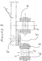
- each end of the metal plates 1 ′ comprises a guide plate 3 ′ disposed between said metal plates 1 ′ and the corresponding angles 3, the assembly being made using suitable 3 ⁇ bolts or screws.
- the internal edges of these guide plates 3 ′ having a length identical to or slightly less than the width of the metal plates 1 ′, constitute lateral stops for the rollers 4 ′ outside of the rolling chains 4.
- the device according to the present invention can in particular be used in the context of continuous compression under high pressures (manufacture of panels using binders), transfer of products under high pressure (stretching) or transport heavy vehicles (excavator, backhoe).
Abstract
Description
La présente invention concerne un dispositif à ruban métallique articulé, notamment, mais non exclusivement, pour le déplacement de charges très lourdes.The present invention relates to an articulated metal strip device, in particular, but not exclusively, for the movement of very heavy loads.
Par le brevet français n° 2 512 135 on connaît une chaîne de roulement constituant un moyen pour le déplacement sous forte pression d'une surface mobile par rapport à une surface fixe.By French Patent No. 2,512,135 there is known a rolling chain constituting a means for the displacement under high pressure of a movable surface relative to a fixed surface.
Cette surface mobile est constituée dans de nombreuses applications par un ruban sans fin entourant une ou plusieurs chaînes de roulement tractées par un arbre moteur au moins, muni de pignons venant s'engrener dans ces chaînes. Ce ruban sans fin constitué généralement par des plaques rectangulaires et de même épaisseur en acier, articulées entre elles, est disposé librement autour des chaînes de roulement. Par conséquent, aucun lien mécanique positif entre le ruban et les chaînes de roulement n'est réalisé, le ruban n'étant entraîné de ce fait que lorsqu'il est suffisamment chargé et ne permettant absolument pas son déplacement à l'encontre de forces longitudinales opposées. En outre, aucun guidage, ni maintien spécifique du ruban articulé n'est prévu.This mobile surface is constituted in many applications by an endless ribbon surrounding one or more rolling chains towed by at least one drive shaft, provided with sprockets coming to mesh in these chains. This endless ribbon generally consisting of rectangular plates and of the same thickness in steel, hinged together, is freely placed around the rolling chains. Consequently, no positive mechanical link between the ribbon and the rolling chains is produced, the ribbon being driven thereby only when it is sufficiently loaded and absolutely not allowing its movement against longitudinal forces. opposite. In addition, no guidance or specific maintenance of the articulated ribbon is provided.
On connaît, par ailleurs, par la demande de brevet français n° 2 592 695 une chaîne de roulement à crémaillère permettant d'assurer un lien mécanique positif entre le ruban et la chaîne de roulement correspondante.We also know from French patent application No. 2,592,695 a rack-and-pinion rolling chain which ensures a positive mechanical link between the ribbon and the corresponding rolling chain.
Néanmoins, la solution proposée dans ce document présente différents inconvénients, notamment la nécessité d'utiliser des chaînes de roulement hors standard coûteuses et d'entraîner de nombreuses opérations d'usinage de grande précision. De plus, la chaîne de roulement proposée mangue de fiabilité et est sujettte à une usure importante en fonctionnement.However, the solution proposed in this document has various drawbacks, in particular the need to use costly non-standard rolling chains and to involve numerous high-precision machining operations. In addition, the rolling chain proposed reliability mango and is subject to significant wear in operation.
En outre, dans ces dispositifs connus, la chaîne de roulement et le ruban sont supportés par des arbres différents entraînant une structure relativement complexe.In addition, in these known devices, the rolling chain and the ribbon are supported by different shafts resulting in a relatively complex structure.
Le problème posé à la présente invention est donc de concevoir un dispositif à ruban métallique articulé présentant une structure simple, réalisée au moyen de pièces et d'éléments standard, ne nécessitant aucun usinage de précision et dont l'encombrement total est faible.The problem posed by the present invention is therefore to design an articulated metal ribbon device having a simple structure, produced by means of standard parts and elements, requiring no precision machining and the overall size of which is small.
L'invention a également pour but de permettre de réaliser les fonctions suivantes dans un dispositif à ruban métallique articulé du type précité :
- assemblage articulé des plaques constituant le ruban métallique entre elles ;
- translation du ruban lorsque celui-ci n'est pas chargé;
- répartition des efforts de traction et de pression exercés sur le ruban et sur les chaînes de roulement ;
- maintien du ruban perpendiculairement à sa surface ;
- guidage du ruban sous des charges faibles, ainsi que sous des charges élevées.
- articulated assembly of the plates constituting the metal strip therebetween;
- translation of the ribbon when it is not loaded;
- distribution of the tensile and pressure forces exerted on the ribbon and on the rolling chains;
- holding the tape perpendicular to its surface;
- guiding the tape under light loads, as well as under heavy loads.
Enfin, l'invention a pour but de concevoir un dispositif à ruban métallique articulé présentant une très faible usure en fonctionnement, ainsi qu'une très grande fiabilité d'utilisation.Finally, the invention aims to design an articulated metal ribbon device having very little wear in operation, as well as very high reliability of use.
A cet effet, l'invention a pour objet un dispositif à ruban métallique articulé, notamment pour le déplacement de charges lourdes, principalement constitué d'un ruban sans fin entourant une ou plusieurs chaînes de roulement comportant des galets et circulant autour d'un bâti, ledit ruban étant formé de plaques métalliques articulées, caractérisé en ce qu'à chaque bord latéral du ruban est disposée une chaîne de manutention, chacune des plaques métalliques étant reliée à au moins un des maillons de chaque chaîne de manutention, et en ce que les pignons engrenant la ou les chaînes de roulement sont disposés, à chaque extrémité du dispositif, entre les pignons engrenant les chaînes de manutention et sur le même arbre que ces derniers, le rapport d'entraînement entre les deux types de pignons étant tel que la vitesse linéaire du ruban métallique sans fin est égale au double de la vitesse linéaire des chaînes de roulement.To this end, the subject of the invention is an articulated metal ribbon device, in particular for moving heavy loads, mainly consisting of an endless ribbon surrounding one or more rolling chains comprising rollers and circulating around a frame. , said ribbon being formed of articulated metal plates, characterized in that at each lateral edge of the ribbon is arranged a handling chain, each of metal plates being connected to at least one of the links of each handling chain, and in that the sprockets meshing the rolling chain or chains are arranged, at each end of the device, between the sprockets meshing the handling chains and on the same as for the latter, the drive ratio between the two types of sprockets being such that the linear speed of the endless metal strip is twice the linear speed of the rolling chains.
L'invention sera mieux comprise, grâce à la description ci-après, gui se rapporte à un mode de réalisation préféré, donné à titre d'exemple non limitatif, et expliqué avec référence aux dessins schématiques annexés, dans lesquels :
- la figure 1 est une vue partielle en élévation latérale et en coupe représentant une moitié d'un dispositif conforme à l'invention ;
- la figure 2 est une vue partielle en coupe suivant A-A′ du dispositif représenté à la figure 1 ;
- la figure 3 est une vue de détail et en coupe de l'extrémité d'une plaque métallique faisant partie du dispositif représenté à la figure 1, selon une variante de réalisation de l'invention.
- Figure 1 is a partial side elevational view in section showing half of a device according to the invention;
- Figure 2 is a partial sectional view along AA 'of the device shown in Figure 1;
- Figure 3 is a detail view in section of the end of a metal plate forming part of the device shown in Figure 1, according to an alternative embodiment of the invention.
Conformément à l'invention et comme le montrent plus particulièrement, à titre d'exemple, les figures 1 et 2 des dessins annexés, le dispositif à ruban métallique 1 articulé est caractérisé en ce qu'à chaque bord latéral du ruban 1 est disposée une chaîne de manutention 2, chacune des plaques métalliques 1′ étant reliée à au moins un des maillons 2′ de chaque chaîne de manutention 2, et en ce que les pignons 13 engrenant la ou les chaînes de roulement 4 sont disposés, à chaque extrémité du dispositif, entre les pignons 11 engrenant les chaînes de manutention 2 et sur le même arbre 8 que ces derniers, le rapport d'entraînement entre les deux types de pignons 11 et 13 étant tel que la vitesse linéaire du ruban métallique 1 sans fin est égale au double de la vitesse linéaire des chaînes de roulement 4.According to the invention and as shown more particularly, by way of example, Figures 1 and 2 of the accompanying drawings, the hinged
Afin d'obtenir la constitution totale d'un dispositif conforme à l'invention, il suffit de reproduire par symétrie par rapport au trait interrompu mixte de coupe la moitié représentée sur la figure 1.In order to obtain the total constitution of a device according to the invention, it suffices to reproduce by symmetry with respect to the broken dashed line of cut the half represented in FIG. 1.
De même, la coupe transversale totale du dispositif selon A-A′ représenté à la figure 1 peut être déduite de la figure 2.Likewise, the total cross section of the device according to A-A ′ shown in FIG. 1 can be deduced from FIG. 2.
Comme le montre la figure 1 des dessins annexés, la largeur des plaques métalliques 1′ est égale au pas ou à un multiple du pas des chaînes de manutention 2.As shown in FIG. 1 of the accompanying drawings, the width of the
Selon un mode de réalisation préféré de l'invention, les pignons 11 engrenant les chaînes de manutention 2 présentent un diamètre primitif et, lorsque les chaînes de manutention 2 et de roulement 4 sont du même type, également un nombre de dents double de ceux des pignons 13 engrenant les chaînes de roulement 4.According to a preferred embodiment of the invention, the
Cette disposition permet de figer physiquement le rapport de 2 à 1 entre la vitesse linéaire du ruban métallique 1 articulé et la vitesse linéaire des chaînes de roulement 4, ce quel que soit le diamètre des galets 4′ desdites chaînes de roulement 4.This arrangement makes it possible to physically freeze the ratio of 2 to 1 between the linear speed of the articulated
Ainsi, il est possible de rendre nul le glissement entre les galets 4′ de la chaîne de roulement 4 et les plaques métalliques 1′ prenant appui sur ces derniers et donc de limiter considérablement l'usure desdits galets 4′.Thus, it is possible to nullify the slip between the rollers 4 ′ of the rolling chain 4 and the
Le type de chaînes de roulement 4 et, éventuellement, de chaînes de manutention 2 mis en oeuvre dans le cadre de l'invention est préférentiellement celui connu par la norme internationale "ISO 1977".The type of rolling chains 4 and, optionally, handling
Conformément à une caractéristique de l'invention, également représentée aux figures 1 et 2 des dessins annexés, les pignons 11 engrenant les chaînes de manutention 2 et les pignons 13 engrenant les chaînes de roulement 4 sont clavetés sur l'un au moins des deux arbres 8, selon que l'un seulement ou que les deux arbres 8 sont moteurs.In accordance with a feature of the invention, also shown in Figures 1 and 2 of the drawings attached, the
Il est possible ainsi au moyen d'un unique dispositif d'entraînement du type moto-réducteur-variateur (non représenté), disposé à l'extrémité de l'unique arbre moteur 8 au moins, d'entraîner simultanément et de manière complémentaire les chaînes de roulement 4 et les chaînes de manutention 2, et de répartir, ainsi, les forces de traction en fonction du mode d'utilisation du dispositif conforme à l'invention.It is thus possible by means of a single drive device of the geared motor-variator type (not shown), disposed at the end of the
En effet, lorsque le ruban métallique 1 est soumis à un effort longitudinal important opposé à sa direction de déplacement et de manière concomitante à une charge relativement faible, un renforcement des chaînes de manutention 2 pourra pallier au mangue d'entraînement dudit ruban 1 par les chaînes de roulement 4 et permettre de remédier aux défauts de perpendicularité des plaques 1′ pouvant survenir dans de telles conditions de mise en oeuvre.In fact, when the
Dans certaines applications du dispositif, notamment lorsque des efforts de translation très élevés sont requis par rapport aux efforts de pression, les chaînes de manutention 2 seront d'un type dont la résistance de rupture est plus élevée que celle des chaînes de roulement 4, les pignons 11 d'engrenement des chaînes de manutention 2 étant alors directement clavetés sur les arbres 8. Dans ces cas, les chaînes de manutention 2 pourront être choisies préférentiellement de type A dans la série incluse dans la norme internationale "ISO 1977", les chaînes de roulement 4 étant du type B de la même série.In certain applications of the device, in particular when very high translational forces are required relative to the pressure forces, the
Afin d'éviter une rupture des chaînes dans des conditions d'utilisation extrêmes, les pignons d'entraînement 11 engrenant les chaînes de manutention 2 sont solidaires de l'arbre 8 moteur correspondant par l'intermédiaire d'un limiteur de couple 12, avantageusement du type à friction réglable.In order to avoid breaking the chains under extreme conditions of use, the
L'effort de traction maximum devant être appliqué à la chaîne de manutention 2 pourra être déterminé en agissant sur un écrou de réglage 12′ comprimant une ou plusieurs rondelles élastiques 12˝, avantageusement du type Belleville, prenant appui directement ou par l'intermédiaire d'une pièce supplémentaire sur les pignons 11 engrenant les chaînes de manutention 2 (figure 2), permettant de régler la force de solidarisation desdits pignons 11 avec l'arbre 8 moteur correspondant.The maximum tensile force to be applied to the
Les pignons 13 engrenant les chaînes de roulement 4 sont avantageusement disposés décalés en rotation les uns par rapport aux autres sur les arbres 8, de telle manière que les galets 4′ des chaînes de roulement 4 constituent des points d'appui en quinconce pour les plaques 1′ du ruban métallique 1 sur le bâti 5.The
Chaque arbre 8 comporte ainsi plusieurs pignons 13 clavetés au moyen d'une clavette 9, fonction du nombre de chaînes de roulement 4 présentes, lesdits pignons 13 étant séparés par des entretoises 13′ et disposés entre les pignons 11 engrenant les chaînes de manutention 2. Les arbres 8 sont maintenus dans des paliers 7 correspondants disposés symétriquement de chaque côté latéral du dispositif et à chacune de ses extrémités, lesdits paliers 7 étant solidaires du bâti 5 au moyen de supports 6.Each
Comme le montre la figure 2 des dessins annexés, les plaques métalliques 1′ constituant le ruban métallique 1 articulé sont fixées aux maillons 2′ des chaînes de manutention 2 au moyen d'éléments 3 en forme de cornières, lesdites chaînes de manutention 2 comportant des galets 2˝ dont le diamètre est inférieur à la largeur de ses maillons 2′ et circulant sur des rails 15 de guidage et de maintien supérieur et inférieur au niveau de chemins de roulement 15′ correspondants.As shown in FIG. 2 of the accompanying drawings, the
Ainsi, le maintien du ruban métallique 1 dans une direction perpendiculaire au plan du dispositif conforme à l'invention est assuré, autant au niveau de la face supérieure dudit dispositif, comportant la surface mobile fonctionnelle S, qu'au niveau de sa face inférieure, où s'effectue la trajectoire de retour des chaînes de roulement 4 et du ruban métallique 1 articulé.Thus, the maintenance of the
En fonctionnement, les galets 2˝ des chaînes de manutention 2 prennent appui sur les chemins de roulement 15′ des rails 15 supérieurs et inférieurs solidaires du bâti 5.In operation, the
Or, le bâti 5, ainsi que les plaques métalliques 1′, au niveau de leurs faces inférieures tournées vers le bâti 5, comportent des rainures 1˝ et 5˝ de largeur sensiblement égale à la largeur des galets 4′ des chaînes de roulement 4, assurant le guidage du ruban métallique 1 articulé et des chaînes de roulement 4.However, the
Par conséquent, les rails 15 supérieurs, par leur action sur les galets 2˝, maintiennent les galets 4′ des chaînes de roulement 4 prisonniers dans les rainures 1˝ et 5˝, respectivement des plaques métalliques 1′ et du bâti 5, assurant ainsi un guidage optimal du ruban métallique 1 et donc de la surface mobile, même en présence de forces de pression très élevées.Consequently, the
Les rails 15 inférieurs jouent un rôle de support, le brin de retour du ruban 1 venant prendre appui par son poids propre sur le chemin de roulement 15′.The
Conformément à un mode de réalisation de l'invention, représenté notamment à la figure 1 des dessins annexés, la distance H′ entre l'axe 8′ des arbres 8 et la surface fonctionnelle mobile S formée par les plaques 1′ du ruban métallique 1 articulé est supérieure à la distance H constituée par le rayon des pignons 11 engrenant les chaînes de manutention 2 augmenté de l'épaisseur desdites plaques 1′, permettant ainsi de réaliser, en intégrant dans une même structure deux dispositifs conformes à l'invention, dont les surfaces mobiles fonctionnelles sont opposées, une presse continue pouvant fonctionner à des pressions très élevées.According to an embodiment of the invention, shown in particular in Figure 1 of the accompanying drawings, the distance H ′ between the
Dans ces conditions, le bâti 5 comporte également, à chacune de ses extrémités, une rampe inclinée 5′, préférentiellement de forme concave, infléchissant la trajectoire des chaînes de roulement 4 vers le pignon 13 correspondant.Under these conditions, the
Ces rampes inclinées 5′ présentent également des rainures 5˝ pour le guidage des galets 4' des chaînes de roulement 4, disposées dans le prolongement des rainures 5˝ du bâti 5.These
Selon une variante de réalisation de l'invention, représentée à la figure 3 des dessins annexés, chaque extrémité des plaques métalliques 1′ comporte une plaquette de guidage 3′ disposée entre lesdites plaques métalliques 1′ et les cornières 3 correspondantes, l'assemblage étant réalisé au moyen de boulons ou de vis 3˝ adaptés. Les bords internes de ces plaquettes de guidage 3′, présentant une longueur identique ou légèrement inférieure à la largeur des plaques métalliques 1′, constituent des butées latérales pour les galets 4′ extérieurs des chaînes de roulement 4.According to an alternative embodiment of the invention, shown in Figure 3 of the accompanying drawings, each end of the
Il est ainsi possible d'éviter un usinage onéreux des plaques métalliques, généralement composées d'un acier laminé très dur, en vue de réaliser les rainures 1˝ et de réduire sensiblement l'épaisseur nécessaire desdites plaques métalliques 1′.It is thus possible to avoid expensive machining of the metal plates, generally composed of a very hard rolled steel, in order to produce the
Néanmoins, lorsque les pignons 11 engrenant les chaînes de manutention 2 sont tous clavetés sur les arbres 8 correspondants et que les pignons d'entraînement 11 fixés sur l'arbre moteur 8 sont montés fous, le guidage du ruban métallique 1 au moyen des rainures 1˝ ou des plaquettes 3′ n'est pas absolument nécessaire, la perpendicularité des plaques métalliques 1′ par rapport à la direction de déplacement étant assurée par les chaînes de manutention 2.However, when the
Grâce à l'invention, il est, par conséquent, possible de réaliser un dispositif à ruban métallique articulé permettant de remplir l'ensemble des fonctions indiquées précédemment, et ce sous la forme d'une structure simple et peu encombrante présentant une grande fiabilité du fait notamment d'une usure faible de ses pièces constitutives en fonctionnement, ainsi qu'un prix de revient peu élevé découlant de l'utilisation de nombreuses pièces standard et d'un nombre d'opérations d'usinage limité.Thanks to the invention, it is therefore possible to produce an articulated metal strip device making it possible to fulfill all of the functions indicated above, and this in the form of a simple and space-saving structure having high reliability of the made in particular of low wear of its constituent parts in operation, as well as a low cost price resulting from the use of numerous standard parts and a limited number of machining operations.
Le dispositif conforme à la présente invention peut notamment être mis en oeuvre dans le cadre de la compression en continu sous fortes pressions (fabrication de panneaux à l'aide de liants), du transfert de produits sous pressions élevées (étirage) ou encore du transport de véhicules lourds (excavatrice, pelleteuse).The device according to the present invention can in particular be used in the context of continuous compression under high pressures (manufacture of panels using binders), transfer of products under high pressure (stretching) or transport heavy vehicles (excavator, backhoe).
Bien entendu, l'invention n'est pas limitée aux modes de réalisation décrits et représentés aux dessins annexés. Des modifications restent possibles, notamment du point de vue de la constitution des divers éléments ou par substitution d'équivalents techniques, sans sortir pour autant du domaine de protection de l'invention.Of course, the invention is not limited to the embodiments described and shown in the accompanying drawings. Modifications remain possible, in particular from the point of view of the constitution of the various elements or by substitution of technical equivalents, without thereby departing from the scope of protection of the invention.
Claims (11)
Applications Claiming Priority (2)
| Application Number | Priority Date | Filing Date | Title |
|---|---|---|---|
| FR9015141 | 1990-11-28 | ||
| FR9015141A FR2669610B3 (en) | 1990-11-28 | 1990-11-28 | DEVICE CONSTITUTING AN ENDLESS METAL TAPE SURROUNDING ONE OR MORE BEARING CHAINS. |
Publications (3)
| Publication Number | Publication Date |
|---|---|
| EP0488919A2 true EP0488919A2 (en) | 1992-06-03 |
| EP0488919A3 EP0488919A3 (en) | 1992-12-16 |
| EP0488919B1 EP0488919B1 (en) | 1995-10-11 |
Family
ID=9402859
Family Applications (1)
| Application Number | Title | Priority Date | Filing Date |
|---|---|---|---|
| EP91440099A Expired - Lifetime EP0488919B1 (en) | 1990-11-28 | 1991-11-21 | Device with articulated metal band, in particular for shifting heavy loads |
Country Status (11)
| Country | Link |
|---|---|
| US (1) | US5174437A (en) |
| EP (1) | EP0488919B1 (en) |
| JP (1) | JP3038269B2 (en) |
| AT (1) | ATE128938T1 (en) |
| CA (1) | CA2056247C (en) |
| DE (1) | DE69113758T2 (en) |
| DK (1) | DK0488919T3 (en) |
| ES (1) | ES2080931T3 (en) |
| FI (1) | FI96408C (en) |
| FR (1) | FR2669610B3 (en) |
| GR (1) | GR3018604T3 (en) |
Cited By (4)
| Publication number | Priority date | Publication date | Assignee | Title |
|---|---|---|---|---|
| EP0621217A2 (en) * | 1993-04-21 | 1994-10-26 | Roberts Sinto Corporation | Chain conveyor with frictionally driven recirculated pallets linked together in sub groupings |
| US5934862A (en) * | 1996-08-06 | 1999-08-10 | E.D. Etnyre & Co. | Conveyor mechanism |
| US6186732B1 (en) | 1996-08-06 | 2001-02-13 | E.D. Etnyre & Co. | Conveyor mechanism |
| CN101293594B (en) * | 2007-09-29 | 2010-06-09 | 张建平 | Distant range traction slide conveyer belt apparatus |
Families Citing this family (11)
| Publication number | Priority date | Publication date | Assignee | Title |
|---|---|---|---|---|
| US5303817A (en) * | 1993-06-25 | 1994-04-19 | The Laitram Corporation | Drive system for modular link conveyor belts |
| US5778287A (en) * | 1997-01-21 | 1998-07-07 | Xerox Corporation | Electrophotographic imaging apparatus having an improved belt drive system |
| DE29802927U1 (en) * | 1998-02-19 | 1999-09-02 | Winklhofer & Soehne Gmbh | Support device |
| US6119848A (en) * | 1999-01-22 | 2000-09-19 | Hartness International | Conveyor motor drive unit and conveyor system |
| IT1317542B1 (en) * | 2000-05-15 | 2003-07-09 | Re M S R L | CONVEYOR DEVICE |
| RU2477250C2 (en) * | 2007-09-17 | 2013-03-10 | Врх Вальтер Райст Холдинг Аг | Rotary device for conveyor |
| US8177056B2 (en) * | 2007-11-20 | 2012-05-15 | Wrh Walter Reist Holding Ag | Drive for conveyor means or conveyed objects |
| CH701687A1 (en) * | 2009-08-24 | 2011-02-28 | Wrh Walter Reist Holding Ag | Method for operating a support device for support of supported objects and a supporting device. |
| DE202011105077U1 (en) * | 2011-08-27 | 2012-11-28 | Hans Hundegger | Belt or chain arrangement and woodworking plant with such a belt or chain arrangement |
| AT16486U1 (en) * | 2016-10-24 | 2019-10-15 | Lhb Mining Solutions Gmbh | conveyor system |
| CN112456036A (en) * | 2020-12-11 | 2021-03-09 | 四川德胜集团钒钛有限公司 | Heavy plate feeder under bracing device |
Citations (5)
| Publication number | Priority date | Publication date | Assignee | Title |
|---|---|---|---|---|
| DE823088C (en) * | 1949-06-04 | 1951-11-29 | Hermann Basler | Method and device for dewatering, preforming and deforming a fiber cake |
| GB864983A (en) * | 1957-11-05 | 1961-04-12 | Burger Raymond | Continuous chain press |
| DE2636604A1 (en) * | 1976-08-13 | 1978-02-16 | Poisel Otto Karl | High speed conveyor chain - is driven from linear motor via belt and balls to double speed |
| EP0073730A1 (en) * | 1981-09-01 | 1983-03-09 | Raymond Burger | Device for the displacement of a compression surface with regard to another one |
| WO1987004139A1 (en) * | 1986-01-07 | 1987-07-16 | Burger, S.A. | Rack-type rolling chaine for exerting a translation force |
Family Cites Families (13)
| Publication number | Priority date | Publication date | Assignee | Title |
|---|---|---|---|---|
| US1141113A (en) * | 1913-01-06 | 1915-06-01 | William Y Gambee | Dumping-device. |
| US1128138A (en) * | 1913-05-29 | 1915-02-09 | James B Hill | Roller-bearing apron-wheel. |
| US1227005A (en) * | 1915-11-29 | 1917-05-22 | Allis Chalmers Mfg Co | Tractor. |
| US1731609A (en) * | 1922-12-11 | 1929-10-15 | American Manganese Steel Co | Conveyer |
| US2371747A (en) * | 1943-04-24 | 1945-03-20 | Nat Automotive Fibres Inc | Conveyer structure |
| US3195712A (en) * | 1961-06-07 | 1965-07-20 | Pirelli | Movable conveyor-type strip for pedestrians |
| JPS4891771A (en) * | 1972-03-06 | 1973-11-29 | ||
| CH570317A5 (en) * | 1973-05-16 | 1975-12-15 | Battelle Memorial Institute | |
| US3985225A (en) * | 1975-03-05 | 1976-10-12 | Sergei Alexeevich Baum | Chain conveyor with support chain |
| SU568573A1 (en) * | 1975-11-05 | 1977-08-15 | Всесоюзный Ордена Трудового Красного Знамени Научно-Исследовательский Горно-Металлургичевкий Институт Цветных Металлов | Belt conveyer |
| SU975512A1 (en) * | 1981-03-27 | 1982-11-23 | Предприятие П/Я Р-6205 | Slate conveyer |
| US4720008A (en) * | 1984-08-17 | 1988-01-19 | National Conveyor Corporation | Conveyor assembly |
| SU1339067A1 (en) * | 1986-04-18 | 1987-09-23 | Специальное Конструкторское Бюро Машин Точного Литья При Тираспольском Заводе Литейных Машин Им.С.М.Кирова | Conveyer |
-
1990
- 1990-11-28 FR FR9015141A patent/FR2669610B3/en not_active Expired - Fee Related
-
1991
- 1991-11-21 DE DE69113758T patent/DE69113758T2/en not_active Expired - Fee Related
- 1991-11-21 ES ES91440099T patent/ES2080931T3/en not_active Expired - Lifetime
- 1991-11-21 AT AT91440099T patent/ATE128938T1/en not_active IP Right Cessation
- 1991-11-21 EP EP91440099A patent/EP0488919B1/en not_active Expired - Lifetime
- 1991-11-21 DK DK91440099.9T patent/DK0488919T3/en active
- 1991-11-25 FI FI915523A patent/FI96408C/en not_active IP Right Cessation
- 1991-11-27 CA CA002056247A patent/CA2056247C/en not_active Expired - Fee Related
- 1991-11-28 JP JP3339648A patent/JP3038269B2/en not_active Expired - Fee Related
- 1991-11-29 US US07/800,484 patent/US5174437A/en not_active Expired - Lifetime
-
1996
- 1996-01-04 GR GR960400001T patent/GR3018604T3/en unknown
Patent Citations (5)
| Publication number | Priority date | Publication date | Assignee | Title |
|---|---|---|---|---|
| DE823088C (en) * | 1949-06-04 | 1951-11-29 | Hermann Basler | Method and device for dewatering, preforming and deforming a fiber cake |
| GB864983A (en) * | 1957-11-05 | 1961-04-12 | Burger Raymond | Continuous chain press |
| DE2636604A1 (en) * | 1976-08-13 | 1978-02-16 | Poisel Otto Karl | High speed conveyor chain - is driven from linear motor via belt and balls to double speed |
| EP0073730A1 (en) * | 1981-09-01 | 1983-03-09 | Raymond Burger | Device for the displacement of a compression surface with regard to another one |
| WO1987004139A1 (en) * | 1986-01-07 | 1987-07-16 | Burger, S.A. | Rack-type rolling chaine for exerting a translation force |
Cited By (5)
| Publication number | Priority date | Publication date | Assignee | Title |
|---|---|---|---|---|
| EP0621217A2 (en) * | 1993-04-21 | 1994-10-26 | Roberts Sinto Corporation | Chain conveyor with frictionally driven recirculated pallets linked together in sub groupings |
| EP0621217A3 (en) * | 1993-04-21 | 1995-02-22 | Roberts Sinto Corp | Chain conveyor with frictionally driven recirculated pallets linked together in sub groupings. |
| US5934862A (en) * | 1996-08-06 | 1999-08-10 | E.D. Etnyre & Co. | Conveyor mechanism |
| US6186732B1 (en) | 1996-08-06 | 2001-02-13 | E.D. Etnyre & Co. | Conveyor mechanism |
| CN101293594B (en) * | 2007-09-29 | 2010-06-09 | 张建平 | Distant range traction slide conveyer belt apparatus |
Also Published As
| Publication number | Publication date |
|---|---|
| GR3018604T3 (en) | 1996-04-30 |
| FI96408B (en) | 1996-03-15 |
| CA2056247A1 (en) | 1992-05-29 |
| DE69113758D1 (en) | 1995-11-16 |
| US5174437A (en) | 1992-12-29 |
| CA2056247C (en) | 1999-02-02 |
| DE69113758T2 (en) | 1997-02-13 |
| ATE128938T1 (en) | 1995-10-15 |
| JP3038269B2 (en) | 2000-05-08 |
| ES2080931T3 (en) | 1996-02-16 |
| EP0488919A3 (en) | 1992-12-16 |
| JPH04298407A (en) | 1992-10-22 |
| EP0488919B1 (en) | 1995-10-11 |
| DK0488919T3 (en) | 1996-08-12 |
| FI915523A0 (en) | 1991-11-25 |
| FR2669610A1 (en) | 1992-05-29 |
| FI96408C (en) | 1996-06-25 |
| FR2669610B3 (en) | 1993-03-05 |
| FI915523A (en) | 1992-05-29 |
Similar Documents
| Publication | Publication Date | Title |
|---|---|---|
| EP0488919B1 (en) | Device with articulated metal band, in particular for shifting heavy loads | |
| FR2533008A1 (en) | ROUND LINK CHAIN, PARTICULARLY FOR SQUEEGEE CONVEYOR | |
| EP0143820A1 (en) | Gear transmission comprising two worm screws. | |
| FR2549450A1 (en) | ROLLER DRIVE UNIT, IN PARTICULAR FOR MOVING OBJECTS ON A CONVEYOR BELT | |
| WO2016092211A2 (en) | Transmission device of an engine, particularly for an engine with variable compression rate and/or variable displacement | |
| EP1914193A1 (en) | Scissor lift | |
| FR2988627A1 (en) | MULTI-CYLINDER ROLLER | |
| EP3568612B1 (en) | Thrust chain device | |
| FR2688852A1 (en) | HYDROMECHANICAL DRIVE SYSTEM FOR TRAINING VEHICLES OF PUBLIC WORKS OR THE LIKE. | |
| FR2486609A1 (en) | GEAR FOR BELT TRANSMISSION | |
| EP0001364A1 (en) | Device for lowering or lifting the upper platform of a car-carrying transporter | |
| EP0007264A1 (en) | Chain flexible in only one direction and application to a hand rail | |
| FR2753679A1 (en) | Scraper for vehicle endless track | |
| WO2018100315A1 (en) | Linkage for the transmission mechanisms | |
| FR2632037A1 (en) | CONTINUOUS VARIATION TRANSMISSION WITH FLAT BELT | |
| FR2797670A1 (en) | Variable transmission for bicycle has wheel with fingers extending into two or more rings to be selectively engaged by transmission belt | |
| FR2523639A1 (en) | Hauling installation for excavator - has guided chain to act as rack engaged by driven toothed wheel | |
| FR2892785A1 (en) | Mechanical transmission security device for load e.g. vehicle, transporting wagon`s reducer, has screw spindle with sliding gear comprising driving bolt permitting to temporarily suppress irreversibility function of reducer | |
| FR2646151A1 (en) | TIGHTENING BLOCK WITH SELF-TIGHTENING JAWS, ESPECIALLY FOR A LINEAR HYDRAULIC WINCH | |
| EP2628888B1 (en) | Electromechanical actuator of a rotational drive for a load with a torque limiter | |
| FR2737513A1 (en) | WORKING STRUCTURE, IN PARTICULAR FOR BREAKING CROSSES BY VEHICLES AND SYSTEM FOR TRANSFERRING AND REMOVING SUCH A STRUCTURE | |
| FR2655634A1 (en) | Caged cylinder with telescopic hollow rods and use thereof | |
| FR2539730A1 (en) | Adherence winch | |
| FR2819737A1 (en) | APPARATUS FOR GRINDING MATERIAL | |
| WO1987004139A1 (en) | Rack-type rolling chaine for exerting a translation force |
Legal Events
| Date | Code | Title | Description |
|---|---|---|---|
| PUAI | Public reference made under article 153(3) epc to a published international application that has entered the european phase |
Free format text: ORIGINAL CODE: 0009012 |
|
| AK | Designated contracting states |
Kind code of ref document: A2 Designated state(s): AT BE CH DE DK ES FR GB GR IT LI LU NL SE |
|
| PUAL | Search report despatched |
Free format text: ORIGINAL CODE: 0009013 |
|
| AK | Designated contracting states |
Kind code of ref document: A3 Designated state(s): AT BE CH DE DK ES FR GB GR IT LI LU NL SE |
|
| 17P | Request for examination filed |
Effective date: 19921112 |
|
| 17Q | First examination report despatched |
Effective date: 19940623 |
|
| GRAA | (expected) grant |
Free format text: ORIGINAL CODE: 0009210 |
|
| AK | Designated contracting states |
Kind code of ref document: B1 Designated state(s): AT BE CH DE DK ES FR GB GR IT LI LU NL SE |
|
| REF | Corresponds to: |
Ref document number: 128938 Country of ref document: AT Date of ref document: 19951015 Kind code of ref document: T |
|
| REF | Corresponds to: |
Ref document number: 69113758 Country of ref document: DE Date of ref document: 19951116 |
|
| ITF | It: translation for a ep patent filed |
Owner name: STUDIO INGG. FISCHETTI & WEBER |
|
| REG | Reference to a national code |
Ref country code: CH Ref legal event code: NV Representative=s name: KIRKER & CIE SA |
|
| GBT | Gb: translation of ep patent filed (gb section 77(6)(a)/1977) |
Effective date: 19960108 |
|
| REG | Reference to a national code |
Ref country code: ES Ref legal event code: FG2A Ref document number: 2080931 Country of ref document: ES Kind code of ref document: T3 |
|
| REG | Reference to a national code |
Ref country code: DK Ref legal event code: EGB |
|
| REG | Reference to a national code |
Ref country code: GR Ref legal event code: FG4A Free format text: 3018604 |
|
| REG | Reference to a national code |
Ref country code: DK Ref legal event code: EGE |
|
| REG | Reference to a national code |
Ref country code: DK Ref legal event code: T3 |
|
| PLBE | No opposition filed within time limit |
Free format text: ORIGINAL CODE: 0009261 |
|
| STAA | Information on the status of an ep patent application or granted ep patent |
Free format text: STATUS: NO OPPOSITION FILED WITHIN TIME LIMIT |
|
| 26N | No opposition filed | ||
| PGFP | Annual fee paid to national office [announced via postgrant information from national office to epo] |
Ref country code: GR Payment date: 19980914 Year of fee payment: 8 |
|
| PGFP | Annual fee paid to national office [announced via postgrant information from national office to epo] |
Ref country code: LU Payment date: 19990301 Year of fee payment: 9 |
|
| PG25 | Lapsed in a contracting state [announced via postgrant information from national office to epo] |
Ref country code: GR Free format text: LAPSE BECAUSE OF NON-PAYMENT OF DUE FEES Effective date: 19991130 |
|
| PG25 | Lapsed in a contracting state [announced via postgrant information from national office to epo] |
Ref country code: LU Free format text: LAPSE BECAUSE OF NON-PAYMENT OF DUE FEES Effective date: 20001121 |
|
| REG | Reference to a national code |
Ref country code: GB Ref legal event code: 732E |
|
| REG | Reference to a national code |
Ref country code: GB Ref legal event code: IF02 |
|
| PGFP | Annual fee paid to national office [announced via postgrant information from national office to epo] |
Ref country code: FR Payment date: 20021120 Year of fee payment: 12 |
|
| PGFP | Annual fee paid to national office [announced via postgrant information from national office to epo] |
Ref country code: ES Payment date: 20031028 Year of fee payment: 13 |
|
| PGFP | Annual fee paid to national office [announced via postgrant information from national office to epo] |
Ref country code: GB Payment date: 20031030 Year of fee payment: 13 Ref country code: BE Payment date: 20031030 Year of fee payment: 13 |
|
| PGFP | Annual fee paid to national office [announced via postgrant information from national office to epo] |
Ref country code: SE Payment date: 20031031 Year of fee payment: 13 |
|
| PGFP | Annual fee paid to national office [announced via postgrant information from national office to epo] |
Ref country code: DK Payment date: 20031104 Year of fee payment: 13 |
|
| PGFP | Annual fee paid to national office [announced via postgrant information from national office to epo] |
Ref country code: AT Payment date: 20031112 Year of fee payment: 13 |
|
| PGFP | Annual fee paid to national office [announced via postgrant information from national office to epo] |
Ref country code: CH Payment date: 20040122 Year of fee payment: 13 |
|
| PGFP | Annual fee paid to national office [announced via postgrant information from national office to epo] |
Ref country code: DE Payment date: 20040130 Year of fee payment: 13 |
|
| PG25 | Lapsed in a contracting state [announced via postgrant information from national office to epo] |
Ref country code: FR Free format text: LAPSE BECAUSE OF NON-PAYMENT OF DUE FEES Effective date: 20040730 |
|
| REG | Reference to a national code |
Ref country code: FR Ref legal event code: ST |
|
| PGFP | Annual fee paid to national office [announced via postgrant information from national office to epo] |
Ref country code: NL Payment date: 20041112 Year of fee payment: 14 |
|
| PG25 | Lapsed in a contracting state [announced via postgrant information from national office to epo] |
Ref country code: GB Free format text: LAPSE BECAUSE OF NON-PAYMENT OF DUE FEES Effective date: 20041121 Ref country code: AT Free format text: LAPSE BECAUSE OF NON-PAYMENT OF DUE FEES Effective date: 20041121 |
|
| PG25 | Lapsed in a contracting state [announced via postgrant information from national office to epo] |
Ref country code: SE Free format text: LAPSE BECAUSE OF NON-PAYMENT OF DUE FEES Effective date: 20041122 Ref country code: ES Free format text: LAPSE BECAUSE OF NON-PAYMENT OF DUE FEES Effective date: 20041122 |
|
| PG25 | Lapsed in a contracting state [announced via postgrant information from national office to epo] |
Ref country code: LI Free format text: LAPSE BECAUSE OF NON-PAYMENT OF DUE FEES Effective date: 20041130 Ref country code: DK Free format text: LAPSE BECAUSE OF NON-PAYMENT OF DUE FEES Effective date: 20041130 Ref country code: CH Free format text: LAPSE BECAUSE OF NON-PAYMENT OF DUE FEES Effective date: 20041130 Ref country code: BE Free format text: LAPSE BECAUSE OF NON-PAYMENT OF DUE FEES Effective date: 20041130 |
|
| BERE | Be: lapsed |
Owner name: *BURGER RAYMOND Effective date: 20041130 |
|
| PG25 | Lapsed in a contracting state [announced via postgrant information from national office to epo] |
Ref country code: DE Free format text: LAPSE BECAUSE OF NON-PAYMENT OF DUE FEES Effective date: 20050601 |
|
| REG | Reference to a national code |
Ref country code: DK Ref legal event code: EBP |
|
| EUG | Se: european patent has lapsed | ||
| GBPC | Gb: european patent ceased through non-payment of renewal fee |
Effective date: 20041121 |
|
| REG | Reference to a national code |
Ref country code: CH Ref legal event code: PL |
|
| PG25 | Lapsed in a contracting state [announced via postgrant information from national office to epo] |
Ref country code: IT Free format text: LAPSE BECAUSE OF NON-PAYMENT OF DUE FEES;WARNING: LAPSES OF ITALIAN PATENTS WITH EFFECTIVE DATE BEFORE 2007 MAY HAVE OCCURRED AT ANY TIME BEFORE 2007. THE CORRECT EFFECTIVE DATE MAY BE DIFFERENT FROM THE ONE RECORDED. Effective date: 20051121 |
|
| REG | Reference to a national code |
Ref country code: ES Ref legal event code: FD2A Effective date: 20041122 |
|
| PG25 | Lapsed in a contracting state [announced via postgrant information from national office to epo] |
Ref country code: NL Free format text: LAPSE BECAUSE OF NON-PAYMENT OF DUE FEES Effective date: 20060601 |
|
| NLV4 | Nl: lapsed or anulled due to non-payment of the annual fee |
Effective date: 20060601 |
|
| BERE | Be: lapsed |
Owner name: *BURGER RAYMOND Effective date: 20041130 |