EP0488903A2 - Laserstrahle-Farbbildanzeigevorrichtung - Google Patents
Laserstrahle-Farbbildanzeigevorrichtung Download PDFInfo
- Publication number
- EP0488903A2 EP0488903A2 EP91403250A EP91403250A EP0488903A2 EP 0488903 A2 EP0488903 A2 EP 0488903A2 EP 91403250 A EP91403250 A EP 91403250A EP 91403250 A EP91403250 A EP 91403250A EP 0488903 A2 EP0488903 A2 EP 0488903A2
- Authority
- EP
- European Patent Office
- Prior art keywords
- laser beam
- wavelength
- color image
- display apparatus
- image display
- Prior art date
- Legal status (The legal status is an assumption and is not a legal conclusion. Google has not performed a legal analysis and makes no representation as to the accuracy of the status listed.)
- Granted
Links
Images


Classifications
-
- H—ELECTRICITY
- H04—ELECTRIC COMMUNICATION TECHNIQUE
- H04N—PICTORIAL COMMUNICATION, e.g. TELEVISION
- H04N5/00—Details of television systems
- H04N5/66—Transforming electric information into light information
-
- H—ELECTRICITY
- H04—ELECTRIC COMMUNICATION TECHNIQUE
- H04N—PICTORIAL COMMUNICATION, e.g. TELEVISION
- H04N9/00—Details of colour television systems
- H04N9/12—Picture reproducers
- H04N9/31—Projection devices for colour picture display, e.g. using electronic spatial light modulators [ESLM]
- H04N9/3129—Projection devices for colour picture display, e.g. using electronic spatial light modulators [ESLM] scanning a light beam on the display screen
Definitions
- the present invention relates to a laser beam color image display apparatus for controlling laser beams to display a color image on a display screen, and more particularly to a laser beam color image display apparatus for controlling laser beams to display a television color image or the like on a display screen.
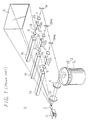
- the laser beam color image display apparatus has three laser beam sources, i.e., an argon gas laser beam source 1G for emitting a green laser beam Lg, a krypton gas laser beam source 1R for emitting a red laser beam Lr, and an argon gas laser beam source 1B for emitting a blue laser beam Lb.
- three laser beam sources i.e., an argon gas laser beam source 1G for emitting a green laser beam Lg, a krypton gas laser beam source 1R for emitting a red laser beam Lr, and an argon gas laser beam source 1B for emitting a blue laser beam Lb.
- the laser beam color image display apparatus also includes intensity modulators 2G, 2R, 2B, such for example as acoustooptic intensity modulators, for modulating the intensities of the laser beams from the laser beam sources 1G, 1R, 1B independently of each other, a polygon mirror 3 for deflecting the laser beams horizontally, a galvanometer mirror 4 for deflecting the laser beams vertically, and a projection display screen 5 onto which the laser beams are projected to display a color image thereon.
- intensity modulators 2G, 2R, 2B such for example as acoustooptic intensity modulators, for modulating the intensities of the laser beams from the laser beam sources 1G, 1R, 1B independently of each other
- a polygon mirror 3 for deflecting the laser beams horizontally
- a galvanometer mirror 4 for deflecting the laser beams vertically
- a projection display screen 5 onto which the laser beams are projected to display a color image thereon.
- Lens systems 6, 7 are positioned on both sides of the intensity modulators 2G, 2R, 2B, and lens systems 8, 9 are disposed between the polygon mirror 3 and the galvanometer mirror 4.
- a reflecting mirror M is positioned to reflect the laser beam that comes from the intensity modulator 2G through the associated lens system 7.
- Blue- and red-reflecting dichroic mirrors DM B , DM R are positioned to reflect the laser beams that come from the intensity modulators 2B, 2R, respectively, through the associated lens systems 7.
- the green laser beam Lg which has a wavelength of 514.5 nm, emitted from the argon gas laser beam source 1G is supplied to the intensity modulator 2G, and modulated in intensity with a green signal component Sg of a video signal that is applied to the intensity modulator 2G.
- the red laser beam Lr which has a wavelength of 647.1 nm, emitted from the krypton gas laser beam source 1R is supplied to the intensity modulator 2R, and modulated in intensity with a red signal component Sr of the video signal that is applied to the intensity modulator 2R.
- the blue laser beam Lb which has a wavelength of 476.5 nm, emitted from the argon gas laser beam source 1B is supplied to the intensity modulator 2B, and modulated in intensity with a blue signal component Sb of the video signal that is applied to the intensity modulator 2R.
- the green, red, and blue laser beams Lg, Lr, Lb to be applied to the intensity modulators 2G, 2R, 2B are separated from the laser beams emitted from the laser beam sources 1G, 1R, 1B by respective color separation dichroic mirrors (not shown).
- the intensity-modulated laser beams Lg, Lr, Lb are then reflected respectively by the reflecting mirror M, the red-reflecting dichroic mirror DM R , and the blue-reflecting dichroic mirror DM B toward the polygon mirror 3.
- the polygon mirror 3 comprises a polygonal mirror 13 that is rotated by an actuator 12.
- the laser beams are horizontally deflected by the rotating polygonal mirror 13, and applied through the lens systems 8, 9 to the galvanometer mirror 4.
- the galvanometer mirror 4, which is angularly moved reciprocally by an actuator 14, then deflects the laser beams vertically while projecting them onto the display screen 5. Since the laser beams are deflected horizontally by the polygon mirror 3 and vertically by the galvanometer mirror 4, the laser beams applied to the display screen 5 scan the display screen 5 in a raster mode, displaying a color image on the display screen 5 based on the video signal.
- the red laser beam Lr of the wavelength of 647.7 nm is produced with an output power of 2 W
- the green laser beam Lg of the wavelength of 514.5 nm is produced with an output power of 0.73 W
- the blue laser beam Lb of the wavelength of 476.5 nm is produced with an output power of 0.87 W.
- the raster on the display screen 5 provides the standard illuminant C (white light) of 540 lumens.
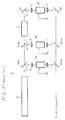
- FIG. 2 shows another conventional laser beam color image display apparatus, generally designated by B.
- the laser beam color image display apparatus B has an argon gas laser beam source 16 for emitting green and blue laser beams and a dye laser beam source 17 that is excited by the remaining laser beam produced by the argon laser beam source 16 to emit a red laser beam.
- the laser beam emitted from the argon gas laser beam source 16 is applied to a blue-reflecting dichroic mirror DM B1 which separates blue laser beams Lb having respective wavelengths of 457.9 nm and 476.5 nm. These separated blue laser beams Lb are supplied to an intensity modulator 2B through a lens system 6.
- the laser beam that has passed through the blue-reflecting dichroic mirror DM B1 is then applied to a green-reflecting dichroic mirror DM G1 which separates a green laser beam Lg having a wavelength of 514.5 nm.
- the separated green laser beam is supplied to an intensity modulator 2G through a lens system 6.
- the remaining laser beam that has passed through the green-reflecting dichroic mirror DM B1 is applied to excite the dye laser beam source 17, which then emits a red laser beam Lr having a wavelength of 612 nm that is reflected by a reflecting mirror M1 to an intensity modulator 2R through a lens system 6.
- the blue, green, and red laser beams Lb, Lg, Lr supplied to the intensity modulators 2B, 2G, 2R are modulated in intensity by blue, green, and red signal components Sb, Sg, Sr of a video signal that are applied respectively to the intensity modulators 2B, 2G, 2R.
- the intensity-modulated laser beams Lb, Lg, Lr are thereafter applied through respective lens systems 7 to a reflecting mirror M2 and dichroic mirrors Dm G2 , DM B2 , by which they are reflected to a light deflector that comprises a polygon mirror, lens systems, a galvanometer mirror identical to those shown in FIG. 1.
- the laser beams are horizontally and vertically deflected by the light deflector to scan a display screen to display a color image thereon.
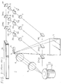
- FIG. 3 shows still another conventional laser beam color image display apparatus, generally designated by C.
- the laser beam color image display apparatus C has a single argon-krypton mixed gas laser beam source 19 for emitting a laser beam from which blue, green, and red laser beams Lb, Lg, Lr are separated.
- Those parts shown in FIG. 3 which correspond to those shown in FIGS. 1 and 2 are denoted by corresponding reference characters.
- the laser beam emitted from the argon-krypton mixed gas laser beam source 19 is applied to a blue-reflecting dichroic mirror DM B1 which separates argon blue laser beams Lb having respective wavelengths of 457.9 nm and 476.5 nm.
- the laser beam that has passed through the blue-reflecting dichroic mirror DM B1 is then applied to a green-reflecting dichroic mirror DM G1 which separates an argon green laser beam Lg having a wavelength of 514.5 nm.
- the remaining laser beam i.e., a krypton red laser beam Lr having a wavelength of 647.1 nm, that has passed through the green-reflecting dichroic mirror DM G1 is reflected by a reflecting mirror M1.
- the blue, green, and red laser beams Lb, Lg, Lr are then supplied to respective intensity modulators 2B, 2G, 2R by which they are modulated in intensity by blue, green, and red signal components Sb, Sg, Sr of a video signal that are applied respectively to the intensity modulators 2B, 2G, 2R.
- the intensity-modulated laser beams Lb, Lg, Lr are thereafter applied through respective lens systems 7 to the dichroic mirrors DM G2 , DM B2 and the reflecting mirror M2 by which they are reflected to the polygon mirror 3.
- the laser beams Lb, Lg, Lr are deflected horizontally by the polygon mirror 3, pass through lens systems 8, 9, and then deflected vertically by the galvanometer mirror 4 to scan the display screen 5 to display a color image thereon.
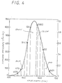
- the krypton gas laser beam source 1R cannot produce a red laser beam with a high output power, and the red laser beam Lr of the wavelength of 647.1 nm has a low specific luminosity of 0.12 (see FIG. 4). Therefore, the luminance of the image displayed on the display screen is relatively low and cannot be increased because it is limited by the output power of the red laser beam Lr.
- the red laser beam Lr is produced by the dye laser beam source 17 excited by the argon gas laser beam
- the image displayed on the display screen is brighter than the image displayed by the laser beam color image display apparatus shown in FIG. 1.
- the dye laser beam source 17 employs a rhodamine dye as a laser material and is excited by an argon gas laser beam with an output power of 6 W
- the dye laser beam source 17 emits a red laser beam having a wavelength of 612 nm with an output power of about 2 W.
- the red laser beam of the wavelength of 612 nm has a higher specific luminosity of 0.478 (see FIG.
- the image displayed on the display screen has a luminance of 650 lumens as a whole.
- the monochromatic light of the red laser beam of the wavelength of 612 nm is sufficient to cover the red range in the NTSC television system.
- the handling and maintenance of the dye laser beam source 17 is not easy since the laser material is a liquid and has to be circulated as a laminar jet flow within the resonator.
- difficulty has been experienced with dye layers in producing a laser beam in good TEM00 mode compared with argon and krypton gas lasers. Laser beams in poor mode conditions give rise to energy loss in intensity modulators.
- the dye laser beam source 17 requires the exciting laser beam source to have an output power capability of 6 W. Therefore, the laser beam color image display apparatus B shown in FIG. 2 cannot easily be reduced in size. Another problem is that the dye in the dye laser beam source 17 must be cooled in the circulation system for increased service life.
- the laser beam color image display apparatus C shown in FIG. 8 also poses limitations on the illuminance of the displayed image because the red laser beam is produced by a krypton gas laser and has a wavelength of 647.1 nm
- a laser beam color image display apparatus comprising first laser beam generating means for generating a blue laser beam, second laser beam generating means for generating a green laser beam, third laser beam generating means for generating a red laser beam, the third laser beam generating means comprising mixing means for adding a laser beam having a wavelength of 568.2 nm and a laser beam having a wavelength of 647.1 nm by way of active mixture, thereby generating the red laser beam, and scanning means for scanning a display screen with the blue laser beam, the green laser beam, and the red laser beam to display a color image on the display screen.
- the mixing means adds the laser beam having the wavelength of 568.2 nm and the laser beam having the wavelength of 647.1 nm at an output power ratio of 1 : 20.
- the red laser beam generated by the third laser beam generating means has a wavelength of 612 nm.
- the third laser beam generating means comprises an argon-krypton mixed gas laser beam source or a krypton gas laser beam source.
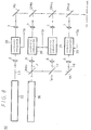
- FIG. 1 shows a laser beam color image display apparatus according to an embodiment of the present invention.
- the laser beam color image display apparatus comprises an argon-krypton mixed gas laser beam source 21 for emitting a laser beam, intensity modulators 2B, 2G, 2Y, 2R such for example as acoustooptic intensity modulators for independently modulating the intensities of blue, green, yellow, and red laser beams separated from the laser beam produced by the argon-krypton mixed gas laser beam source 21, a polygon mirror 3 for horizontally deflecting the intensity-modulated laser beams, the polygon mirror 3 being composed of a polygonal mirror 13 and an actuator 12 for rotating the polygonal mirror 13, a galvanometer mirror 4 for vertically deflecting the laser beams that have been horizontally deflected, and a display screen 5.
- intensity modulators 2B, 2G, 2Y, 2R such for example as acoustooptic intensity modulators for independently modulating the intensities of blue, green, yellow, and red laser beams separated from the
- the laser beam color image display apparatus 22 also includes blue-reflecting dichroic mirrors DM B1 , DM B2 , green-reflecting dichroic mirrors DM G1 , DM G2 , yellow-reflecting dichroic mirrors DM Y1 , DM Y2 , reflecting mirrors M1, M2, lens systems 6, 7 disposed one on each side of the intensity modulators 2B, 2G, 2Y, 2R, and lens systems 8, 9 disposed between the polygon mirror 3 and the galvanometer mirror 4.
- blue-reflecting dichroic mirrors DM B1 , DM B2 green-reflecting dichroic mirrors DM G1 , DM G2 , yellow-reflecting dichroic mirrors DM Y1 , DM Y2 , reflecting mirrors M1, M2, lens systems 6, 7 disposed one on each side of the intensity modulators 2B, 2G, 2Y, 2R, and lens systems 8, 9 disposed between the polygon mirror 3 and the galvanometer mirror 4.
- the laser beam emitted from the argon-krypton mixed gas laser beam source 21 is applied to the blue-reflecting dichroic mirror DM B1 which separates argon blue laser beams Lb having respective wavelengths of 457.9 nm and 476.5 nm. These separated blue laser beams Lb are supplied to the intensity modulator 2B through the lens system 6, and modulated in intensity with a blue signal component Sb of a video signal that is supplied to the intensity modulator 2B.
- the laser beam that has passed through the blue-reflecting dichroic mirror DM B1 is then applied to the green-reflecting dichroic mirror DM G1 which separates an argon green laser beam Lg having a wavelength of 514.5 nm (which may also separate a krypton laser beam having a wavelength of 520.8 nm and an argon laser beam having a wavelength of 528.7 nm).
- the separated green laser beam Lg is supplied to the intensity modulator 2G through the lens system 6, and modulated in intensity with a green signal component Sg of the video signal that is supplied to the intensity modulator 2G.
- the laser beam that has passed through the green-reflecting dichroic mirror DM G1 is then applied to the yellow-reflecting dichroic mirror DM Y1 which separates a krypton yellow laser beam Ly having a wavelength of 568.2 nm.
- the separated yellow laser beam Ly is supplied to the intensity modulator 2Y through the lens system 6, and modulated in intensity with a yellow signal component Sy of the video signal that is supplied to the intensity modulator 2Y.
- the remaining laser beam, i.e., a krypton red laser beam Lr having a wavelength of 647.1 nm, that has passed through the yellow-reflecting dichroic mirror DM Y1 is reflected by the reflecting mirror M1 and supplied to the intensity modulator 2R through the lens system 6.
- the red laser beam Lr is modulated in intensity with a red signal component SR of the video signal that is supplied to the intensity modulator 2R.
- the intensity-modulated laser beams Lb, Lg, Ly, Lr are thereafter applied through the respective lens systems 7 to the dichroic mirrors DM B2 , DM G2 , DM Y2 and the reflecting mirror M2 by which they are reflected to the polygon mirror 3.
- the laser beams Lb, Lg, Ly, Lr are horizontally deflected by the rotating polygonal mirror 13, and applied through the lens systems 8, 9 to the galvanometer mirror 4.
- the galvanometer mirror 4 which is angularly moved reciprocally by the actuator 14, then deflects the laser beams vertically while projecting them onto the display screen 5.
- the laser beams are deflected horizontally by the polygon mirror 3 and vertically by the galvanometer mirror 4, the laser beams applied to the display screen 5 scan the display screen 5 in a raster mode, displaying a color image on the display screen 5 based on the video signal.
- the yellow laser beam Ly of the wavelength of 568.2 nm and the red laser beam Lr of the wavelength of 647.1 nm are added by way of active mixture by the dichroic mirror DM Y2 , providing the red light of the displayed image. More specifically, the yellow laser beam Ly of the wavelength of 568.2 nm and the red laser beam Lr of the wavelength of 647.1 nm are added at an output power ratio of 1 : 20, producing red light which is equivalent to monochromatic light having a wavelength of about 612 nm.
- the blue laser beams Lb of the wavelengths of 457.9 nm and 476.5 nm are also added at an output power ratio of 1 : 2, producing blue light which is equivalent to monochromatic light having a wavelength of about 470 nm.
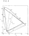
- the color range that can be expressed by the laser beam color image display apparatus 22 is shown in the chromaticity diagram of FIG. 9.
- the solid-line curve I indicates the color range of the laser beam color image display apparatus 22 shown in FIG. 5.
- the broken-line curve II indicates the color range of the conventional laser beam color image display apparatus C shown in FIG. 3.
- the dot-and-dash-line curve III shows the color range according to the NTSC standard three primary colors.
- the two-dot-and-dash-line curve IV shows the color range according to the HDTV (high-definition television) standard primary colors.
- the laser beam color image display apparatus 22 shown in FIG. 5 can cover the color range according to the NTSC standard three primary colors substantially in its entirety, and can cover the color range according to the HDTV standard primary colors (which can substantially be reproduced by the present cathode-ray- tube television system).
- Tables 1, 2, and 3, given below, show laser beam output powers at respective wavelengths required to provide the standard illuminant C (white color) of 700 lumens.
- Table 1 shows laser beam output powers in the conventional laser beam color image display apparatus B shown in FIG. 2 which employs an argon laser beam source and a dye laser beam source.
- Table 2 shows laser beam output powers in the conventional laser beam color image display apparatus C shown in FIG. 3 which employs an argon-krypton mixed gas laser beam source.
- Table 3 shows laser beam output powers in the laser beam color image display apparatus 22 shown in FIG. 5 which employs an argon-krypton mixed gas laser beam source.
- the output power ratio of the argon-krypton mixed gas laser beam source can be optimized by the mixture ratio of argon and krypton gases, the curvature of the mirrors of the resonator, and the reflective coatings.
- the laser beam color image display apparatus expresses the red light of the displayed image by adding the krypton laser beam of the wavelength of 568.2 nm and the krypton laser beam of the wavelength of 647.1 nm by way of active mixture.
- the luminance of the resulting red light is greater by the luminance of the added laser beam of the wavelength of 568.2 nm.
- the laser beam color image display apparatus according to the present invention is used as a practical laser beam color image display apparatus for television, it can display color images with greater luminance and has a lower electric power requirement than the conventional laser beam color image display apparatus.
- the laser beam color image display apparatus according to the present invention requires less maintenance, is smaller in size, and less expensive than the conventional laser beam color image display apparatus which employs dye laser.
- FIGS. 6 through 8 show laser beam color image display apparatus according to other embodiments of the present invention. Those parts shown in FIGS. 6 through 8 which correspond to those shown in FIG. 5 are denoted by corresponding reference characters.
- the laser beam color image display apparatus has three laser beam sources, i.e., an argon gas laser beam source 31, a krypton gas laser beam source 32, and an argon gas laser beam source 33.
- the argon gas laser beam source 31 emits blue laser beams Lb having respective wavelengths of 476.5 nm and 457.9 nm.
- the argon gas laser beam source 33 emits a green laser beam Lg having a wavelength of 514.5 nm.
- the blue and green laser beams Lb, Lg thus emitted are supplied to respective intensity modulators 2B, 2G, and modulated in intensity with blue and green signal components Sb, Sg, respectively, of a video signal that are supplied to the intensity modulators 2B, 2G.
- the krypton gas laser beam source 32 emits a laser beam which is supplied to a yellow-reflecting dichroic mirror DM Y1 .
- the yellow-reflecting dichroic mirror DM Y1 separates the laser beam into a red laser beam Lr having a wavelength of 647.1 nm and a yellow laser beam Ly having a wavelength of 568.2 nm.
- the separated red and yellow laser beams Lr, Ly are supplied through the dichroic mirror DM Y1 and a reflecting mirror M1, respectively, to respective intensity modulators 2R, 2Y, and modulated in intensity with a red signal component Sr of the video signal that is supplied to the intensity modulators 2R, 2Y.
- the intensity-modulated laser beams Lr, Ly are added by way of active mixture, providing the red light of a displayed image.
- the intensity modulated laser beams are then reflected by a reflecting mirror M2 and dichroic mirrors DM R2 , DM Y2 , DM B2 to a light deflector.
- the light deflector which is composed of a polygon mirror and a galvanometer mirror, and a display screen (not shown in FIG. 6) are identical to those shown in FIG. 5.
- the laser beam color image display apparatus has two laser beam sources, i.e., an argon gas laser beam source 35 and a krypton gas laser beam source 36.
- the laser beam emitted from the argon gas laser beam source 35 is applied to a blue-reflecting dichroic mirror DM B1 which separates the laser beam into blue laser beams Lb having respective wavelengths of 457.9 nm and 476.5 nm and a green laser beam Lg having a wavelength of 514.5 nm.
- the blue and green laser beams Lb, Lg thus emitted are supplied through the dichroic mirror DM B1 and a reflecting mirror M3, respectively, to respective intensity modulators 2B, 2G, and modulated in intensity with blue and green signal components Sb, Sg, respectively, of a video signal that are supplied to the intensity modulators 2B, 2G.
- the laser beam emitted from the krypton gas laser beam source 36 is supplied to a yellow-reflecting dichroic mirror DM Y1 .
- the yellow-reflecting dichroic mirror DM Y1 separates the laser beam into a red laser beam Lr having a wavelength of 647.1 nm and a yellow laser beam Ly having a wavelength of 568.2 nm.
- the separated red and yellow laser beams Lr, Ly are supplied through the dichroic mirror DM Y1 and a reflecting mirror M1, respectively, to respective intensity modulators 2R, 2Y, and modulated in intensity with a red signal component Sr of the video signal that is supplied to the intensity modulators 2R, 2Y.
- the intensity-modulated laser beams Lr, Ly are added by way of active mixture, providing red light of a displayed image.
- the intensity modulated laser beams are then reflected by a reflecting mirror M2 and dichroic mirrors DM Y2 , DM G2 , DM B2 to a light deflector.
- the light deflector which is composed of a polygon mirror and a galvanometer mirror, and a display screen (not shown in FIG. 7) are identical to those shown in FIG. 5.
- the laser beam color image display apparatus has two laser beam sources, i.e., an argon gas laser beam source 35 and a krypton gas laser beam source 36.
- the argon gas laser beam source 35 supplies blue laser beams Lb having respective wavelengths of 457.9 nm and 476.5 nm to an intensity modulator 2B, and modulated in intensity with a blue signal component Sb of a video signal that is supplied to the intensity modulator 2B.
- the laser beam emitted from the krypton gas laser beam source 36 is supplied to a red-passing dichroic mirror DM R3 .
- the red-passing dichroic mirror DM R3 separates a red laser beam Lr having a wavelength of 647.1 nm from the supplied laser beam.
- the red laser beam Lr is then supplied to an intensity modulator 2R.
- the laser beam reflected by the red-passing dichroic mirror DM R3 is applied to a yellow-reflecting dichroic mirror DM Y1 which separates the laser beam into a yellow laser beam Ly having a wavelength of 568.2 nm and a green laser beam Lg having a wavelength of 520.8 nm.
- the separated yellow and green laser beams Ly, Lg are supplied through the dichroic mirror DM Y1 and a reflecting mirror M1, respectively, to respective intensity modulators 2Y, 2G.
- the laser beams Lb, Lr, Ly, Lg are then modulated in intensity by the respective intensity modulators 2B, 2R, 2Y, 2G with blue, red, yellow, and green signal components Sb, Sr, Sy, Sg of a video signal that are supplied to the intensity modulators 2B, 2R, 2Y, 2G.
- the intensity-modulated laser beams Lr, Ly are added by way of active mixture, providing red light of a displayed image.
- the intensity modulated laser beams are then reflected by a reflecting mirror M2 and dichroic mirrors DM Y2 , DM G2 , DM B2 to a light deflector.
- the light deflector which is composed of a polygon mirror and a galvanometer mirror, and a display screen (not shown in FIG. 8) are identical to those shown in FIG. 5.
- the laser beam color image display apparatus shown in FIGS. 6 through 8 also express the red light of the displayed image by adding the krypton laser beam of the wavelength of 568.2 nm and the krypton laser beam of the wavelength of 647.1 nm by way of active mixture. The luminance of the resulting red light is therefore increased.
- the laser beam color image display apparatus can display color images with greater luminance, have a lower electric power requirement, require less maintenance, are smaller in size, and less expensive than the conventional laser beam color image display apparatus.
- the laser beam color image display apparatus offer various practical advantages make themselves useful in actual applications.
Landscapes
- Engineering & Computer Science (AREA)
- Multimedia (AREA)
- Signal Processing (AREA)
- Physics & Mathematics (AREA)
- Optics & Photonics (AREA)
- Mechanical Optical Scanning Systems (AREA)
- Control Of Indicators Other Than Cathode Ray Tubes (AREA)
- Video Image Reproduction Devices For Color Tv Systems (AREA)
- Lasers (AREA)
Applications Claiming Priority (2)
| Application Number | Priority Date | Filing Date | Title |
|---|---|---|---|
| JP338351/90 | 1990-11-30 | ||
| JP2338351A JPH04204812A (ja) | 1990-11-30 | 1990-11-30 | レーザ画像表示装置 |
Publications (3)
| Publication Number | Publication Date |
|---|---|
| EP0488903A2 true EP0488903A2 (de) | 1992-06-03 |
| EP0488903A3 EP0488903A3 (en) | 1992-08-05 |
| EP0488903B1 EP0488903B1 (de) | 1996-05-08 |
Family
ID=18317334
Family Applications (1)
| Application Number | Title | Priority Date | Filing Date |
|---|---|---|---|
| EP91403250A Expired - Lifetime EP0488903B1 (de) | 1990-11-30 | 1991-11-29 | Laserstrahle-Farbbildanzeigevorrichtung |
Country Status (5)
| Country | Link |
|---|---|
| US (1) | US5255082A (de) |
| EP (1) | EP0488903B1 (de) |
| JP (1) | JPH04204812A (de) |
| KR (1) | KR920011249A (de) |
| DE (1) | DE69119371T2 (de) |
Cited By (13)
| Publication number | Priority date | Publication date | Assignee | Title |
|---|---|---|---|---|
| WO1998024240A1 (en) * | 1996-11-27 | 1998-06-04 | Laser Power Corporation | Multi-beam laser scanning display system |
| US5990983A (en) * | 1994-09-30 | 1999-11-23 | Laser Power Corporation | High resolution image projection system and method employing lasers |
| FR2787591A1 (fr) * | 1998-12-14 | 2000-06-23 | Samsung Electronics Co Ltd | Appareil de projection a laser donnant une image de grandes dimensions |
| US6154259A (en) * | 1996-11-27 | 2000-11-28 | Photera Technologies, Inc. | Multi-beam laser scanning display system with speckle elimination |
| US6281948B1 (en) | 1998-02-09 | 2001-08-28 | Ldt Gmbh & Co. Laser-Display-Technologies Kg | Device for deflection, use thereof, and a video system |
| US6351324B1 (en) | 2000-03-09 | 2002-02-26 | Photera Technologies, Inc. | Laser imaging system with progressive multi-beam scan architecture |
| US6539132B2 (en) | 2000-02-22 | 2003-03-25 | Gennadii Ivtsenkov | Acousto-optical switch for fiber optic lines |
| EP0568998B1 (de) * | 1992-05-06 | 2003-04-16 | Canon Kabushiki Kaisha | Vorrichtung zur Erzeugung von Bildern und ein diese verwendender Projektor |
| EP1203976A3 (de) * | 2000-11-03 | 2004-03-24 | Samsung Electronics Co., Ltd. | Optischer Scanner, Laserprojektor mit optischem Scanner und Verfahren zum Betrieb des Laserprojektors |
| KR100421213B1 (ko) * | 1997-06-05 | 2004-06-24 | 삼성전자주식회사 | 대화면레이저영상투사장치 |
| KR100522671B1 (ko) * | 1998-05-30 | 2006-01-27 | 삼성에스디아이 주식회사 | 레이저 음극선관 |
| KR100611210B1 (ko) * | 2001-03-28 | 2006-08-09 | 삼성에스디아이 주식회사 | 단판식 프로젝션시스템의 광학계 |
| TWI460456B (zh) * | 2011-01-21 | 2014-11-11 | Univ Nat Taipei Technology | 虛擬視覺化系統 |
Families Citing this family (35)
| Publication number | Priority date | Publication date | Assignee | Title |
|---|---|---|---|---|
| KR100202246B1 (ko) * | 1989-02-27 | 1999-06-15 | 윌리엄 비. 켐플러 | 디지탈화 비디오 시스템을 위한 장치 및 방법 |
| FR2694103B1 (fr) * | 1992-07-24 | 1994-08-26 | Thomson Csf | Projecteur d'images en couleurs. |
| JP3076678B2 (ja) * | 1992-08-21 | 2000-08-14 | 松下電器産業株式会社 | 投写形画像表示装置 |
| CN1119482A (zh) * | 1993-02-03 | 1996-03-27 | 尼托公司 | 图像投影的方法和设备 |
| US5481403A (en) * | 1993-06-03 | 1996-01-02 | Volt Information Sciences, Inc. | Dry silver photographic imaging device and method |
| US5546139A (en) * | 1993-06-28 | 1996-08-13 | Bacs, Jr.; Aron | Moving imagery projection system |
| US6175440B1 (en) | 1994-02-02 | 2001-01-16 | Advanced Laser Technologies, Inc. | Laser beam display |
| DE4420558A1 (de) * | 1994-06-13 | 1995-12-14 | Horst Wuerfel | Laserbrille |
| US5517263A (en) * | 1994-07-25 | 1996-05-14 | Proxima Corporation | Image projection system and method of using same |
| US5704700A (en) * | 1994-07-25 | 1998-01-06 | Proxima Corporation | Laser illuminated image projection system and method of using same |
| US5959702A (en) * | 1996-10-04 | 1999-09-28 | Goodman; John Mott | Lensless video projector |
| US6067127A (en) * | 1997-07-08 | 2000-05-23 | Sony Corporation | Method and apparatus for reducing the rotation rate of mirrors in a high resolution digital projection display |
| US6317170B1 (en) * | 1997-09-13 | 2001-11-13 | Samsung Electronics Co., Ltd. | Large screen compact image projection apparatus using a hybrid video laser color mixer |
| US6183092B1 (en) | 1998-05-01 | 2001-02-06 | Diane Troyer | Laser projection apparatus with liquid-crystal light valves and scanning reading beam |
| US6134050A (en) * | 1998-11-25 | 2000-10-17 | Advanced Laser Technologies, Inc. | Laser beam mixer |
| DE19860017A1 (de) * | 1998-12-23 | 2000-06-29 | Ldt Gmbh & Co | Vorrichtung für die Projektion eines Videobildes |
| JP3551058B2 (ja) * | 1999-01-21 | 2004-08-04 | 株式会社日立製作所 | 投写型画像ディスプレイ装置 |
| US6170953B1 (en) * | 1999-03-22 | 2001-01-09 | Samsung Electronics Co., Ltd. | Laser video projector for projecting image to a plurality of screens |
| US6426781B1 (en) * | 1999-03-26 | 2002-07-30 | Samsung Electronics Co., Ltd. | Laser video projector |
| US6698900B1 (en) | 1999-09-21 | 2004-03-02 | Audio Visual Imagineering, Inc. | Reverse projection system for moving imagery |
| US6567605B1 (en) | 2000-08-25 | 2003-05-20 | The Boeing Company | Fiber optic projection device |
| AU2001288427A1 (en) * | 2000-08-25 | 2002-03-04 | The Regents Of The University Of California | Very-large-scale very-high-resolution multiple-projector tiled display with uniform intensity, color temperature and color balance throughout by use of a single light source for each color; intensity and spectral management in all light paths; and optional fresnel lenses behind each display tile |
| US7102700B1 (en) * | 2000-09-02 | 2006-09-05 | Magic Lantern Llc | Laser projection system |
| US6594090B2 (en) * | 2001-08-27 | 2003-07-15 | Eastman Kodak Company | Laser projection display system |
| EP1461656A2 (de) * | 2001-11-06 | 2004-09-29 | Keyotee | Bildprojektionsapparat |
| US6736514B2 (en) * | 2002-06-21 | 2004-05-18 | Eastman Kodak Company | Imaging apparatus for increased color gamut using dual spatial light modulators |
| JP3774715B2 (ja) * | 2002-10-21 | 2006-05-17 | キヤノン株式会社 | 投射型表示装置 |
| US7993285B2 (en) * | 2002-11-05 | 2011-08-09 | Boston Scientific Scimed, Inc. | Medical device having flexible distal tip |
| JP4853033B2 (ja) * | 2005-04-21 | 2012-01-11 | セイコーエプソン株式会社 | 光走査装置及び画像表示装置 |
| CN100363778C (zh) * | 2005-04-21 | 2008-01-23 | 精工爱普生株式会社 | 光扫描装置及图像显示装置 |
| KR100754190B1 (ko) * | 2005-11-03 | 2007-09-03 | 삼성전자주식회사 | 레이저 디스플레이 장치 |
| KR20070080985A (ko) * | 2006-02-09 | 2007-08-14 | 삼성전자주식회사 | 레이저 디스플레이 장치 |
| CN101421661B (zh) * | 2006-04-12 | 2010-08-11 | 松下电器产业株式会社 | 图像显示装置 |
| US20080219303A1 (en) * | 2007-03-02 | 2008-09-11 | Lucent Technologies Inc. | Color mixing light source and color control data system |
| DE102014108905A1 (de) * | 2014-06-25 | 2015-12-31 | Osram Opto Semiconductors Gmbh | Projektionsvorrichtung und Verfahren zur Erzeugung eines Projektionsbildes |
Family Cites Families (5)
| Publication number | Priority date | Publication date | Assignee | Title |
|---|---|---|---|---|
| US3597536A (en) * | 1968-05-10 | 1971-08-03 | Gen Telephone & Elect | Dual beam laser display device employing polygonal mirror |
| US3710015A (en) * | 1971-03-16 | 1973-01-09 | Gte Laboratories Inc | Optical processor for laser display system |
| US3818129A (en) * | 1971-06-30 | 1974-06-18 | Hitachi Ltd | Laser imaging device |
| US3783185A (en) * | 1972-01-28 | 1974-01-01 | Eastman Kodak Co | Multi-color acoustooptic modulator |
| GB1544097A (en) * | 1976-07-22 | 1979-04-11 | Redifon Flight Simulation Ltd | Laser systems |
-
1990
- 1990-11-30 JP JP2338351A patent/JPH04204812A/ja active Pending
-
1991
- 1991-10-12 KR KR1019910017968A patent/KR920011249A/ko not_active Withdrawn
- 1991-11-21 US US07/795,847 patent/US5255082A/en not_active Expired - Lifetime
- 1991-11-29 DE DE69119371T patent/DE69119371T2/de not_active Expired - Fee Related
- 1991-11-29 EP EP91403250A patent/EP0488903B1/de not_active Expired - Lifetime
Cited By (13)
| Publication number | Priority date | Publication date | Assignee | Title |
|---|---|---|---|---|
| EP0568998B1 (de) * | 1992-05-06 | 2003-04-16 | Canon Kabushiki Kaisha | Vorrichtung zur Erzeugung von Bildern und ein diese verwendender Projektor |
| US5990983A (en) * | 1994-09-30 | 1999-11-23 | Laser Power Corporation | High resolution image projection system and method employing lasers |
| WO1998024240A1 (en) * | 1996-11-27 | 1998-06-04 | Laser Power Corporation | Multi-beam laser scanning display system |
| US6154259A (en) * | 1996-11-27 | 2000-11-28 | Photera Technologies, Inc. | Multi-beam laser scanning display system with speckle elimination |
| KR100421213B1 (ko) * | 1997-06-05 | 2004-06-24 | 삼성전자주식회사 | 대화면레이저영상투사장치 |
| US6281948B1 (en) | 1998-02-09 | 2001-08-28 | Ldt Gmbh & Co. Laser-Display-Technologies Kg | Device for deflection, use thereof, and a video system |
| KR100522671B1 (ko) * | 1998-05-30 | 2006-01-27 | 삼성에스디아이 주식회사 | 레이저 음극선관 |
| FR2787591A1 (fr) * | 1998-12-14 | 2000-06-23 | Samsung Electronics Co Ltd | Appareil de projection a laser donnant une image de grandes dimensions |
| US6539132B2 (en) | 2000-02-22 | 2003-03-25 | Gennadii Ivtsenkov | Acousto-optical switch for fiber optic lines |
| US6351324B1 (en) | 2000-03-09 | 2002-02-26 | Photera Technologies, Inc. | Laser imaging system with progressive multi-beam scan architecture |
| EP1203976A3 (de) * | 2000-11-03 | 2004-03-24 | Samsung Electronics Co., Ltd. | Optischer Scanner, Laserprojektor mit optischem Scanner und Verfahren zum Betrieb des Laserprojektors |
| KR100611210B1 (ko) * | 2001-03-28 | 2006-08-09 | 삼성에스디아이 주식회사 | 단판식 프로젝션시스템의 광학계 |
| TWI460456B (zh) * | 2011-01-21 | 2014-11-11 | Univ Nat Taipei Technology | 虛擬視覺化系統 |
Also Published As
| Publication number | Publication date |
|---|---|
| KR920011249A (ko) | 1992-06-27 |
| JPH04204812A (ja) | 1992-07-27 |
| DE69119371D1 (de) | 1996-06-13 |
| EP0488903B1 (de) | 1996-05-08 |
| US5255082A (en) | 1993-10-19 |
| EP0488903A3 (en) | 1992-08-05 |
| DE69119371T2 (de) | 1996-10-02 |
Similar Documents
| Publication | Publication Date | Title |
|---|---|---|
| EP0488903B1 (de) | Laserstrahle-Farbbildanzeigevorrichtung | |
| US7417799B2 (en) | Multi-primary color display | |
| US5715021A (en) | Methods and apparatus for image projection | |
| US7252391B2 (en) | Method of producing an image | |
| US7475993B2 (en) | Light scanning device and image display device | |
| US6170953B1 (en) | Laser video projector for projecting image to a plurality of screens | |
| US20030214633A1 (en) | Method and apparatus for increasing color gamut of a display | |
| EP1596247A1 (de) | Lichtquelle mit vier oder fünf Farben und Projektor | |
| US6426781B1 (en) | Laser video projector | |
| CN113406850B (zh) | 一种投影系统 | |
| US20180192013A1 (en) | Image display device and image display method | |
| US7232224B2 (en) | Simultaneous color illumination | |
| CN112147834B (zh) | 一种光源、投影显示装置及光源调制方法 | |
| US7972001B2 (en) | Projection illumination device and method for projection visual display system using multiple controlled light emitters having individual wavelengths | |
| US7812300B2 (en) | Methods and systems for imaging having an illumination splitting means with a dynamic selecting means and a static selecting means | |
| US7118226B2 (en) | Sequential color recapture for image display systems | |
| WO2007026885A1 (ja) | レーザ画像形成装置およびカラー画像形成方法 | |
| WO2008010651A1 (en) | Image projection system and method | |
| US7387389B2 (en) | Image display system and method | |
| CN210005847U (zh) | 一种光源合束模组、投影显示装置及投影显示设备 | |
| JPH0767064A (ja) | 投射型レーザ画像表示装置 | |
| CN211296855U (zh) | 一种提高投影图像颜色均匀性的dlp投影仪及投影系统 | |
| JP2008275930A (ja) | 投写型映像表示装置 | |
| US12038679B2 (en) | Wavelength conversion apparatus, light source system and display device | |
| KR100255753B1 (ko) | 문자 및 영상 표시용 복수 광학계를 갖는 영상 표시 장치 |
Legal Events
| Date | Code | Title | Description |
|---|---|---|---|
| PUAI | Public reference made under article 153(3) epc to a published international application that has entered the european phase |
Free format text: ORIGINAL CODE: 0009012 |
|
| AK | Designated contracting states |
Kind code of ref document: A2 Designated state(s): DE FR GB |
|
| PUAL | Search report despatched |
Free format text: ORIGINAL CODE: 0009013 |
|
| AK | Designated contracting states |
Kind code of ref document: A3 Designated state(s): DE FR GB |
|
| 17P | Request for examination filed |
Effective date: 19930115 |
|
| 17Q | First examination report despatched |
Effective date: 19941207 |
|
| GRAH | Despatch of communication of intention to grant a patent |
Free format text: ORIGINAL CODE: EPIDOS IGRA |
|
| GRAA | (expected) grant |
Free format text: ORIGINAL CODE: 0009210 |
|
| AK | Designated contracting states |
Kind code of ref document: B1 Designated state(s): DE FR GB |
|
| REF | Corresponds to: |
Ref document number: 69119371 Country of ref document: DE Date of ref document: 19960613 |
|
| ET | Fr: translation filed | ||
| PLBE | No opposition filed within time limit |
Free format text: ORIGINAL CODE: 0009261 |
|
| STAA | Information on the status of an ep patent application or granted ep patent |
Free format text: STATUS: NO OPPOSITION FILED WITHIN TIME LIMIT |
|
| 26N | No opposition filed | ||
| PGFP | Annual fee paid to national office [announced via postgrant information from national office to epo] |
Ref country code: FR Payment date: 20011113 Year of fee payment: 11 |
|
| PGFP | Annual fee paid to national office [announced via postgrant information from national office to epo] |
Ref country code: GB Payment date: 20011128 Year of fee payment: 11 |
|
| PGFP | Annual fee paid to national office [announced via postgrant information from national office to epo] |
Ref country code: DE Payment date: 20011217 Year of fee payment: 11 |
|
| REG | Reference to a national code |
Ref country code: GB Ref legal event code: IF02 |
|
| PG25 | Lapsed in a contracting state [announced via postgrant information from national office to epo] |
Ref country code: GB Free format text: LAPSE BECAUSE OF NON-PAYMENT OF DUE FEES Effective date: 20021129 |
|
| PG25 | Lapsed in a contracting state [announced via postgrant information from national office to epo] |
Ref country code: DE Free format text: LAPSE BECAUSE OF NON-PAYMENT OF DUE FEES Effective date: 20030603 |
|
| GBPC | Gb: european patent ceased through non-payment of renewal fee | ||
| PG25 | Lapsed in a contracting state [announced via postgrant information from national office to epo] |
Ref country code: FR Free format text: LAPSE BECAUSE OF NON-PAYMENT OF DUE FEES Effective date: 20030731 |
|
| REG | Reference to a national code |
Ref country code: FR Ref legal event code: ST |