EP0488507A2 - Système pour contrôler le pourcentage d'eau - Google Patents
Système pour contrôler le pourcentage d'eau Download PDFInfo
- Publication number
- EP0488507A2 EP0488507A2 EP91309200A EP91309200A EP0488507A2 EP 0488507 A2 EP0488507 A2 EP 0488507A2 EP 91309200 A EP91309200 A EP 91309200A EP 91309200 A EP91309200 A EP 91309200A EP 0488507 A2 EP0488507 A2 EP 0488507A2
- Authority
- EP
- European Patent Office
- Prior art keywords
- signal
- fluid
- voltage
- water
- injection
- Prior art date
- Legal status (The legal status is an assumption and is not a legal conclusion. Google has not performed a legal analysis and makes no representation as to the accuracy of the status listed.)
- Granted
Links
- XLYOFNOQVPJJNP-UHFFFAOYSA-N water Substances O XLYOFNOQVPJJNP-UHFFFAOYSA-N 0.000 title claims abstract description 61
- 238000012544 monitoring process Methods 0.000 title claims description 4
- 239000012530 fluid Substances 0.000 claims abstract description 42
- 238000002347 injection Methods 0.000 claims abstract description 36
- 239000007924 injection Substances 0.000 claims abstract description 36
- 238000000926 separation method Methods 0.000 claims 1
- 239000000839 emulsion Substances 0.000 description 10
- 238000000034 method Methods 0.000 description 8
- 238000005259 measurement Methods 0.000 description 7
- 239000003921 oil Substances 0.000 description 6
- 238000010586 diagram Methods 0.000 description 5
- 230000005284 excitation Effects 0.000 description 4
- 238000004519 manufacturing process Methods 0.000 description 4
- 239000012212 insulator Substances 0.000 description 3
- 230000005684 electric field Effects 0.000 description 2
- 239000002184 metal Substances 0.000 description 2
- 239000000523 sample Substances 0.000 description 2
- 125000006850 spacer group Chemical group 0.000 description 2
- 239000004809 Teflon Substances 0.000 description 1
- 229920006362 Teflon® Polymers 0.000 description 1
- 238000009825 accumulation Methods 0.000 description 1
- 230000000694 effects Effects 0.000 description 1
- 239000000295 fuel oil Substances 0.000 description 1
- 238000002847 impedance measurement Methods 0.000 description 1
- 238000000691 measurement method Methods 0.000 description 1
- 239000000203 mixture Substances 0.000 description 1
- 239000003129 oil well Substances 0.000 description 1
- 239000003208 petroleum Substances 0.000 description 1
- 229920001343 polytetrafluoroethylene Polymers 0.000 description 1
- 150000003839 salts Chemical class 0.000 description 1
Images

Classifications
-
- G—PHYSICS
- G01—MEASURING; TESTING
- G01F—MEASURING VOLUME, VOLUME FLOW, MASS FLOW OR LIQUID LEVEL; METERING BY VOLUME
- G01F1/00—Measuring the volume flow or mass flow of fluid or fluent solid material wherein the fluid passes through a meter in a continuous flow
- G01F1/56—Measuring the volume flow or mass flow of fluid or fluent solid material wherein the fluid passes through a meter in a continuous flow by using electric or magnetic effects
- G01F1/64—Measuring the volume flow or mass flow of fluid or fluent solid material wherein the fluid passes through a meter in a continuous flow by using electric or magnetic effects by measuring electrical currents passing through the fluid flow; measuring electrical potential generated by the fluid flow, e.g. by electrochemical, contact or friction effects
-
- G—PHYSICS
- G01—MEASURING; TESTING
- G01N—INVESTIGATING OR ANALYSING MATERIALS BY DETERMINING THEIR CHEMICAL OR PHYSICAL PROPERTIES
- G01N27/00—Investigating or analysing materials by the use of electric, electrochemical, or magnetic means
- G01N27/02—Investigating or analysing materials by the use of electric, electrochemical, or magnetic means by investigating impedance
- G01N27/22—Investigating or analysing materials by the use of electric, electrochemical, or magnetic means by investigating impedance by investigating capacitance
- G01N27/221—Investigating or analysing materials by the use of electric, electrochemical, or magnetic means by investigating impedance by investigating capacitance by investigating the dielectric properties
-
- G—PHYSICS
- G01—MEASURING; TESTING
- G01F—MEASURING VOLUME, VOLUME FLOW, MASS FLOW OR LIQUID LEVEL; METERING BY VOLUME
- G01F1/00—Measuring the volume flow or mass flow of fluid or fluent solid material wherein the fluid passes through a meter in a continuous flow
- G01F1/74—Devices for measuring flow of a fluid or flow of a fluent solid material in suspension in another fluid
-
- G—PHYSICS
- G01—MEASURING; TESTING
- G01F—MEASURING VOLUME, VOLUME FLOW, MASS FLOW OR LIQUID LEVEL; METERING BY VOLUME
- G01F15/00—Details of, or accessories for, apparatus of groups G01F1/00 - G01F13/00 insofar as such details or appliances are not adapted to particular types of such apparatus
- G01F15/08—Air or gas separators in combination with liquid meters; Liquid separators in combination with gas-meters
-
- G—PHYSICS
- G01—MEASURING; TESTING
- G01N—INVESTIGATING OR ANALYSING MATERIALS BY DETERMINING THEIR CHEMICAL OR PHYSICAL PROPERTIES
- G01N33/00—Investigating or analysing materials by specific methods not covered by groups G01N1/00 - G01N31/00
- G01N33/26—Oils; Viscous liquids; Paints; Inks
- G01N33/28—Oils, i.e. hydrocarbon liquids
- G01N33/2823—Raw oil, drilling fluid or polyphasic mixtures
Definitions
- the present invention relates to monitors in general and, more particularly, to water cut monitors, i.e. to monitors for providing a signal representative of the percentage water content in a fluid stream.
- the present invention provides a water cut (percentage) monitor which includes a settling tank in which a quantity of fluid from a producing oil well is accumulated.
- the fluid is removed as a stream of fluid after a predetermined interval from the accumulation of the fluid by the settling tank so as to allow the accumulated fluid to separate into three phases: free water, water-continuous and oil-continuous.
- the flow rate of the stream of fluid is measured and a corresponding flow rate signal is provided as well as a temperature signal representative of a sensed temperature of the stream of fluid.
- the water cut monitor includes a plurality of electrodes in contact with the fluid.
- Injection electronics connected to at least one of the electrodes provides an injection voltage and injection current to the fluid stream and also provides signals corresponding to the injection voltage, injection current and the phase angle between the injection voltage and injection current.
- a voltage in the fluid stream is measured and a measured voltage signal provided.
- a computer determines the water cut of the petroleum stream in accordance with the temperature signal, the injection voltage, the electrical phase angle and injection current signals and the measured voltage signal.
- Figure 1 is a drawing of a water cut monitoring means and method constructed in accordance with the present invention.
- FIG 2 is a flow diagram of the operation of the water cut monitoring means shown in Figure 1.
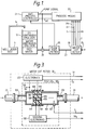
- Figure 3 is a partial simplified block diagram and a partial schematic diagram of one embodiment of the water cut meter shown in Figure 1.
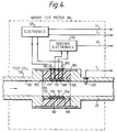
- Figure 4 is a partial simplified block diagram and a partial schematic diagram of another embodiment of the water cut meter shown in Figure 1.
- Oil field production is defined in terms of barrels of oil per day (BOPD) and barrels of water per day (BWPD). These figures are determined by the measurement of flow rate and water cut. Many commercial flowmeters are available which yield satisfactory flow values. A number of commercial water cut meters are also available. Most of these meters, however, are designed for use only when the oil/water mixture is oil continuous, i.e., when any water present is suspended within the oil. These meters function purely as a capacitance measurement and operate properly only when a non-conductive (high impedance) path exists across the measurement electrodes. In water-continuous emulsions, a conducting path exists across the probe which essentially "shorts out" the capacitance measurement.
- the shorting effect is highly sensitive to salinity and temperature changes and renders standard capacitance probes useless in water-continuous operation when only a small amount of salt is present.
- the present invention is inexpensive and can operate over the entire 0 to 100 percent range of water cut, even where high water salinities and heavy oil emulsions are encountered.
- a well under test 3 providing a production stream to the settling tank 10 via line 14.
- a pump 20 controlled by the AWT process controller 21, pumps the fluid from the bottom of tank 10 through a flowmeter 25 and thence through a water cut meter 30, and finally discharges the fluid to the production system, all via a line 23.
- Water cut meter 30 provides five signals to process means 22: the injection voltage V i , the injection current I i , the phase angle PH, the sensed voltage V s , and the temperature T. The obtaining of those signals and their utilization will be explained more fully hereinafter.
- Initial fluid pumped from the bottom of tank 10 is practically always water.
- the water cut system of the present invention measures the impedance of the water (Z water) and retains this value.
- Z water the impedance
- the impedance (Z emulsion) increases.
- Dividing Z emulsion by Z water gives Z ratio, which is proportional to the percent water cut of the water-continuous emulsion.
- the electrical phase angle between V i and I increases dramatically. This increase is used to change the measurement method to an inverse relationship between the injection impedance and percent water cut.
- the present invention can switch back and forth between oil and water-continuous phases with no loss of accuracy. In the event no free water is present in tank 10, a default value of Z water typical of low water wells is assigned.
- block 50 represents pump 20 being turned on by the pump signal.
- the pump signal is used to initialise all the coefficients of values required for all calculations as represented by block 51 entitled "INITIALIZE".
- the following values are initialized: water-continuous equation coefficients A, B, C, D and E; oil-continuous equation coefficients F, G and H; sensed impedance constant KA; temperature curve coefficients AA, BB, and water impedance initial value SWINIT.
- Block 55 entitled “ACQUIRE DATA”
- Block 59 is the next step which calculates averages of the acquired data. From block 59 we proceed to block 62 which raises the question: is number of samples ten?
- Z s cpr Z s + KB x Z s x (DEGC - 40) 4.
- DEGC AA + BB x Temp All of this is represented by block 67 entitled "Correct Z s for temperature”. From block 67 we proceed to block 72 which makes the statement: If Z s corrected is less than Z water, set Z water equal to Z s corrected. This procedure determines the water impedance Z water to be the lowest impedance measurement. If Z s corrected is greater than Z water, the value of Z water is not changed and the next step is represented by block 75 entitled "Calculate Impedance Ratio Zrat". Zrat equals Zscor/Zwater.
- the value of Zrat is used to calculate the water cut of the water-continuous fluid in accordance with the following equation 5: 5.
- WC A+B(Zrat) + C(Zrat)2 + D(Zrat)3 + E(Zrat)4
- This calculated value WC is provided by process means 22 in the form of signal WC to the AWT process controller 21.
- Block 83 inquires if the pump is still on. If so, the processor loops back to block 53 where a new measurement begins. If the pump has gone off, the measurement process is halted (block 95).
- Coefficients for the water-continuous water cut equation are empirically determined by recording values of Zrat as fluid samples are taken. Samples are then analyzed to determine the actual percentage water cut. A plot of water cut WC versus Zrat is then made using computer curve-fitting software. This software can curve fit the plotted points and give the coefficients of the resultant polynomial curve. Data are taken for several different water salinities and a curve is determined which best fits all the data points. Coefficients from this curve are then used in the water-continuous polynomial equation.
- Coefficients for the oil-continuous water cut equation are determined in a similar manner by simultaneously recording values of the injection impedance, Zi, and taking water cut samples when the emulsion is known to be oil-continuous. A curve fit for the WC versus Zi data is then obtained from the curve-fitting program and the coefficients determined. These coefficients are then entered into oil-continuous WC equation 1.
- Test cell 100 includes a housing 101 with flow line adapter pipes 103. Housing 101 has a square cross-section to the fluid flow. Flow line adapters 103 permit connecting of housing 100 to line 23. Test cell 100 also contains three electrodes 104, 105, and 106, mounted along with insulator 108 to form a sensing body 110 having end caps 119. Excitation electronics 125 is connected between ground 118 and electrode 104.
- Excitation electronics 125 has within it an oscillator which provides an AC injection voltage across to an electrode 104 and ground 118 causing an injection current to flow within the fluid.
- the injection voltage in the present invention may be used at substantially lower frequencies or at higher frequencies, a preferred frequency range is from 1 MHz to 50 MHz.
- circuitry that provides signals V i and I i , corresponding to the injection voltage and the injection current, respectively.
- the injection signal provided to electrode 104 creates an electric field within the fluid.
- Electrodes 105 and 106 are electrically connected to sensing electronics 130 which senses the voltage picked up across electrodes 105 and 106 and provides a corresponding signal Vs.
- a temperature sensor 137 senses the temperature of the fluid flowing in housing 23 and provides a corresponding temperature signal T.
- test cell 150 is connected inline with line 23. Although the actual fittings are not shown, obviously test cell 150 includes means for being connected inline to line 23.
- Test cell 150 may be basically made of metal except where noted otherwise.
- test cell 150 includes four electrodes 152, 154, 156 and 157, mounted so that they are inline with the inner surface of line 23.
- electrodes 152 through 157 are circular in nature and are in contact with the fluid passing through the meter. Electrodes 152 through 157 are separated from a metallic body 160 of test cell 150 by polytetrafluoroethylene (Teflon) spacers 165 through 171 which are concentric within Teflon body 180 which is contained within metal cylinder 185.
- Teflon polytetrafluoroethylene
- cylinder 185 has openings 190 which allow the electrical connections of 152 and 154 to excitation electronics 125 and also allows the connections of electrodes 156 and 157 to sensing electronics 130. Further, there are O-rings 195 between each interface of an insulator ring and an electrode and an insulator spacer and metallic body 160.
- the operation of the second embodiment is the same as the first embodiment with the difference being that the injection current between electrodes 152 and 154 produces an electric field which is parallel to the fluid flow instead of perpendicular to the flow as in the first embodiment.
- the temperature is sensed by a temperature sensor 137 as previously described for the other embodiment.
Landscapes
- Chemical & Material Sciences (AREA)
- General Physics & Mathematics (AREA)
- Physics & Mathematics (AREA)
- Health & Medical Sciences (AREA)
- Life Sciences & Earth Sciences (AREA)
- Fluid Mechanics (AREA)
- Chemical Kinetics & Catalysis (AREA)
- Immunology (AREA)
- Analytical Chemistry (AREA)
- Biochemistry (AREA)
- General Health & Medical Sciences (AREA)
- Engineering & Computer Science (AREA)
- Pathology (AREA)
- Electrochemistry (AREA)
- Oil, Petroleum & Natural Gas (AREA)
- General Chemical & Material Sciences (AREA)
- Food Science & Technology (AREA)
- Medicinal Chemistry (AREA)
- Investigating Or Analyzing Materials By The Use Of Electric Means (AREA)
- Water Treatment By Electricity Or Magnetism (AREA)
Applications Claiming Priority (2)
| Application Number | Priority Date | Filing Date | Title |
|---|---|---|---|
| US07/619,621 US5095758A (en) | 1990-11-29 | 1990-11-29 | Water cut monitoring means and method |
| US619621 | 1990-11-29 |
Publications (3)
| Publication Number | Publication Date |
|---|---|
| EP0488507A2 true EP0488507A2 (fr) | 1992-06-03 |
| EP0488507A3 EP0488507A3 (en) | 1993-03-17 |
| EP0488507B1 EP0488507B1 (fr) | 1995-04-05 |
Family
ID=24482656
Family Applications (1)
| Application Number | Title | Priority Date | Filing Date |
|---|---|---|---|
| EP91309200A Expired - Lifetime EP0488507B1 (fr) | 1990-11-29 | 1991-10-08 | Système pour contrôler le pourcentage d'eau |
Country Status (12)
| Country | Link |
|---|---|
| US (1) | US5095758A (fr) |
| EP (1) | EP0488507B1 (fr) |
| JP (1) | JPH0518917A (fr) |
| KR (1) | KR100193004B1 (fr) |
| AU (1) | AU640065B2 (fr) |
| CA (1) | CA2044420A1 (fr) |
| DE (1) | DE69108686T2 (fr) |
| DK (1) | DK0488507T3 (fr) |
| ES (1) | ES2071234T3 (fr) |
| MX (1) | MX9102175A (fr) |
| NO (1) | NO914344L (fr) |
| RU (1) | RU2066750C1 (fr) |
Cited By (2)
| Publication number | Priority date | Publication date | Assignee | Title |
|---|---|---|---|---|
| EP0936462A2 (fr) * | 1998-02-17 | 1999-08-18 | Deutsches Zentrum für Luft- und Raumfahrt e.V. | Méthode et appareil pour la mesure de la teneur de gas volumétriques |
| WO2016071635A1 (fr) * | 2014-11-07 | 2016-05-12 | Snecma | Ensemble de mesure capacitive du taux de gaz dans un ecoulement fluide |
Families Citing this family (30)
| Publication number | Priority date | Publication date | Assignee | Title |
|---|---|---|---|---|
| US5586027A (en) * | 1989-06-12 | 1996-12-17 | Western Atlas International, Inc. | Method and apparatus for determining flow rates in multi-phase fluid flow mixtures |
| IT1258181B (it) * | 1992-08-05 | 1996-02-20 | Apparecchiatura per la determinazione della frazione d'acqua in una corrente di idrocarburi luquidi anche in presenza di gas | |
| US5396806A (en) * | 1993-11-12 | 1995-03-14 | Auburn International, Inc. | On-line mass flow measurement in flowing two component systems |
| US5563518A (en) * | 1994-07-05 | 1996-10-08 | Texaco Inc. | Method of standard dielectric water cut measurement with small gas fraction present |
| FR2760526B1 (fr) * | 1997-03-10 | 1999-04-16 | Elf Aquitaine | Dispositif de mesure |
| DE19728031A1 (de) * | 1997-07-01 | 1999-01-07 | Bernd Horst Dr Meier | Verfahren zur Messung von Volumen und Fluß von bewegten Flüssigkeiten und Vorrichtung zur Messung des Herzzeitvolumens und weiterer Kreislaufparameter |
| AU736392B2 (en) * | 1997-10-22 | 2001-07-26 | Japan National Oil Corporation | Method of measuring flow rates of respective fluids constituting multiphase fluid and flow meter for multiphase flow utilizing the same |
| US6114863A (en) * | 1998-04-29 | 2000-09-05 | General Electric Company | Method for determining the presence of water in materials |
| US6272915B1 (en) * | 1999-04-23 | 2001-08-14 | Baker Hughes Incorporated | Dual transmitter multi-capacitance flow meter |
| US6507401B1 (en) | 1999-12-02 | 2003-01-14 | Aps Technology, Inc. | Apparatus and method for analyzing fluids |
| US6945122B2 (en) * | 2003-06-30 | 2005-09-20 | The Boeing Company | Water cut meter for measurement of water in crude oil-magnetic |
| US7201068B2 (en) * | 2003-06-30 | 2007-04-10 | The Boeing Company | Water cut meter for measurement of water in crude oil |
| US6823271B1 (en) | 2003-06-30 | 2004-11-23 | The Boeing Company | Multi-phase flow meter for crude oil |
| US8915123B2 (en) * | 2012-03-30 | 2014-12-23 | Schlumberger Technology Corporation | Methods and apparatus for determining a viscosity of oil in a mixture |
| US20130265063A1 (en) | 2012-04-06 | 2013-10-10 | Exxonmobil Research And Engineering Company | Method and apparatus for detecting the presence of water in a current of liquid hydrocarbons |
| WO2014058467A1 (fr) * | 2012-10-08 | 2014-04-17 | Los Alamos National Security, Llc | Séparation induite par champs électriques de constituants dans une émulsion |
| US9677394B2 (en) | 2013-06-28 | 2017-06-13 | Schlumberger Technology Corporation | Downhole fluid sensor with conductive shield and method of using same |
| CO7610162A1 (es) * | 2015-11-20 | 2016-05-20 | Ecopetrol Sa | Sistema y método para medición del contenido de agua o corte de agua en mezcla de petróleo/gas-agua |
| US10119929B2 (en) | 2016-06-03 | 2018-11-06 | Mohr and Associates | Method for identifying and measuring volume fraction constituents of a fluid |
| US10048219B2 (en) | 2016-06-03 | 2018-08-14 | Mohr and Associates | Probe for indentifying and measuring volume fraction constituents of a fluid |
| US10119850B2 (en) | 2016-06-03 | 2018-11-06 | Mohr and Associates | Apparatus for identifying and measuring volume fraction constituents of a fluid |
| US10620060B2 (en) * | 2017-07-19 | 2020-04-14 | Georg Fischer Signet, LLC | Combined ultrasonic temperature and conductivity sensor assembly |
| US10670544B2 (en) | 2018-08-13 | 2020-06-02 | Saudi Arabian Oil Company | Impedance-based flowline water cut measurement system |
| EP3897905B1 (fr) * | 2018-11-21 | 2024-03-27 | Cameron Technologies Limited | Angle de phase d'unité de puissance pour commande d'unité de séparation |
| KR102095936B1 (ko) * | 2019-03-20 | 2020-04-01 | 주식회사 솔지 | 동파방지 기능을 구비한 이중 구조의 워터 디텍터 |
| WO2020236859A1 (fr) * | 2019-05-22 | 2020-11-26 | Transtech Systems, Inc. | Système de capteur à plaques parallèles en cours de traitement pour la surveillance de fluides par spectroscopie d'impédance électromagnétique |
| US11187044B2 (en) | 2019-12-10 | 2021-11-30 | Saudi Arabian Oil Company | Production cavern |
| US11460330B2 (en) | 2020-07-06 | 2022-10-04 | Saudi Arabian Oil Company | Reducing noise in a vortex flow meter |
| CN112611854B (zh) * | 2020-12-14 | 2022-11-15 | 昆仑数智科技有限责任公司 | 一种含水量在线分析系统及方法 |
| CN112814649B (zh) * | 2021-01-04 | 2023-03-10 | 天津科技大学 | 一种油井产液含水率智能计量装置及方法 |
Citations (3)
| Publication number | Priority date | Publication date | Assignee | Title |
|---|---|---|---|---|
| US4751842A (en) * | 1987-01-05 | 1988-06-21 | Texaco Inc. | Means and method for measuring a multi-phase distribution within a flowing petroleum stream |
| US4774680A (en) * | 1986-09-19 | 1988-09-27 | Agar Corporation, Ltd. | Method and apparatus for net oil measurement |
| EP0417936A2 (fr) * | 1989-09-12 | 1991-03-20 | Texaco Development Corporation | Dispositif et procédé pour contrôler le pourcentage d'eau |
Family Cites Families (3)
| Publication number | Priority date | Publication date | Assignee | Title |
|---|---|---|---|---|
| AU583581B2 (en) * | 1985-01-24 | 1989-05-04 | Commonwealth Scientific And Industrial Research Organisation | Moisture and density determination |
| US5033289A (en) * | 1988-05-16 | 1991-07-23 | Texaco Inc. | Water cut monitoring means and method |
| FR2637089B1 (fr) * | 1988-09-29 | 1990-11-30 | Schlumberger Prospection | Procede et dispositif pour l'analyse d'un ecoulement a plusieurs phases dans un puits d'hydrocarbures |
-
1990
- 1990-11-29 US US07/619,621 patent/US5095758A/en not_active Expired - Fee Related
-
1991
- 1991-06-12 CA CA002044420A patent/CA2044420A1/fr not_active Abandoned
- 1991-10-08 DK DK91309200.3T patent/DK0488507T3/da active
- 1991-10-08 EP EP91309200A patent/EP0488507B1/fr not_active Expired - Lifetime
- 1991-10-08 ES ES91309200T patent/ES2071234T3/es not_active Expired - Lifetime
- 1991-10-08 DE DE69108686T patent/DE69108686T2/de not_active Expired - Fee Related
- 1991-11-06 NO NO91914344A patent/NO914344L/no unknown
- 1991-11-09 KR KR1019910019906A patent/KR100193004B1/ko not_active IP Right Cessation
- 1991-11-22 AU AU88082/91A patent/AU640065B2/en not_active Ceased
- 1991-11-22 MX MX9102175A patent/MX9102175A/es not_active IP Right Cessation
- 1991-11-28 RU SU915010168A patent/RU2066750C1/ru active
- 1991-11-29 JP JP3339414A patent/JPH0518917A/ja active Pending
Patent Citations (4)
| Publication number | Priority date | Publication date | Assignee | Title |
|---|---|---|---|---|
| US4774680A (en) * | 1986-09-19 | 1988-09-27 | Agar Corporation, Ltd. | Method and apparatus for net oil measurement |
| US4774680B1 (en) * | 1986-09-19 | 1993-10-12 | Agar Corporation Ltd. | Method and apparatus for net oil measurement |
| US4751842A (en) * | 1987-01-05 | 1988-06-21 | Texaco Inc. | Means and method for measuring a multi-phase distribution within a flowing petroleum stream |
| EP0417936A2 (fr) * | 1989-09-12 | 1991-03-20 | Texaco Development Corporation | Dispositif et procédé pour contrôler le pourcentage d'eau |
Cited By (6)
| Publication number | Priority date | Publication date | Assignee | Title |
|---|---|---|---|---|
| EP0936462A2 (fr) * | 1998-02-17 | 1999-08-18 | Deutsches Zentrum für Luft- und Raumfahrt e.V. | Méthode et appareil pour la mesure de la teneur de gas volumétriques |
| EP0936462A3 (fr) * | 1998-02-17 | 2000-12-06 | Deutsches Zentrum für Luft- und Raumfahrt e.V. | Méthode et appareil pour la mesure de la teneur de gas volumétriques |
| US6412351B1 (en) | 1998-02-17 | 2002-07-02 | Deutsches Zentrum Fuer Luft-Und Raumfahrt E.V. | Method and measuring apparatus for determining the volumetric gas content |
| WO2016071635A1 (fr) * | 2014-11-07 | 2016-05-12 | Snecma | Ensemble de mesure capacitive du taux de gaz dans un ecoulement fluide |
| FR3028315A1 (fr) * | 2014-11-07 | 2016-05-13 | Snecma | Systeme ameliore de mesure du taux de gaz dans un ecoulement fluide |
| US10073050B2 (en) | 2014-11-07 | 2018-09-11 | Safran Aircraft Engines | Assembly for capacitive measurement of the amount of gas in a fluid flow |
Also Published As
| Publication number | Publication date |
|---|---|
| US5095758A (en) | 1992-03-17 |
| DK0488507T3 (da) | 1995-06-19 |
| RU2066750C1 (ru) | 1996-09-20 |
| EP0488507B1 (fr) | 1995-04-05 |
| KR920010265A (ko) | 1992-06-26 |
| EP0488507A3 (en) | 1993-03-17 |
| DE69108686T2 (de) | 1995-11-23 |
| CA2044420A1 (fr) | 1992-05-30 |
| NO914344D0 (no) | 1991-11-06 |
| AU640065B2 (en) | 1993-08-12 |
| DE69108686D1 (de) | 1995-05-11 |
| KR100193004B1 (ko) | 1999-06-15 |
| JPH0518917A (ja) | 1993-01-26 |
| NO914344L (no) | 1992-06-01 |
| MX9102175A (es) | 1994-05-31 |
| AU8808291A (en) | 1992-06-04 |
| ES2071234T3 (es) | 1995-06-16 |
Similar Documents
| Publication | Publication Date | Title |
|---|---|---|
| EP0488507B1 (fr) | Système pour contrôler le pourcentage d'eau | |
| EP0417936B1 (fr) | Dispositif et procédé pour contrôler le pourcentage d'eau | |
| US5067345A (en) | Method and apparatus for measuring and calculating bulk water in crude oil or bulk water in steam | |
| EP0510774B1 (fr) | Méthode et dispositif pour mesurer des propriétés d'un écoulement multiphasique | |
| EP0372598B1 (fr) | Dispositif de mesure avec corrélation croisée d'impédance | |
| US6831470B2 (en) | Methods and apparatus for estimating on-line water conductivity of multiphase mixtures | |
| US5736637A (en) | Downhole multiphase flow sensor | |
| Hammer et al. | Capacitance transducers for non-intrusive measurement of water in crude oil | |
| US20040012395A1 (en) | Devices for characterizing a multiphase fluid having a continuous conductive phase | |
| EP0720741A1 (fr) | Procede et technique d'analyse du petrole d'un puits | |
| US7772854B2 (en) | High-conductivity contacting-type conductivity measurement | |
| US5033289A (en) | Water cut monitoring means and method | |
| CN105659075A (zh) | 多相计量中的结垢监测和抑制剂量化技术 | |
| NO304622B1 (no) | Anordning for Õ bestemme vanninnholdet i en petroleumstr°m | |
| US6272906B1 (en) | Device for separating and for measuring the volume of the various phases of a mixture of fluids | |
| US4916940A (en) | Method and apparatus for measuring and calculating bulk water in crude oil | |
| US5489849A (en) | High accuracy calibration-free electrical parameter measurements using differential measurement with respect to immersion depth | |
| EP0433311B1 (fr) | Procede et instrument de mesure de trois elements | |
| EP4165378B1 (fr) | Débitmètre permettant de mesurer la vitesse d'écoulement dans des écoulements continus d'huile | |
| US7201068B2 (en) | Water cut meter for measurement of water in crude oil | |
| JP2000249673A (ja) | 多相流体の成分率測定方法及びそれを利用した成分率計 | |
| RU2798916C1 (ru) | Устройство и способ автоматизированного измерения параметров бурового раствора | |
| SU650024A1 (ru) | Способ определени зар да и электропроводности зар женной диэлектрической жидкости | |
| Lucas et al. | Towards a phase-distribution-independent impedance volume-fraction measurement | |
| Beck et al. | On-line measurement of oil/gas/water mixtures, using a capacitance sensor |
Legal Events
| Date | Code | Title | Description |
|---|---|---|---|
| PUAI | Public reference made under article 153(3) epc to a published international application that has entered the european phase |
Free format text: ORIGINAL CODE: 0009012 |
|
| AK | Designated contracting states |
Kind code of ref document: A2 Designated state(s): DE DK ES FR GB NL |
|
| PUAL | Search report despatched |
Free format text: ORIGINAL CODE: 0009013 |
|
| AK | Designated contracting states |
Kind code of ref document: A3 Designated state(s): DE DK ES FR GB NL |
|
| 17P | Request for examination filed |
Effective date: 19930910 |
|
| 17Q | First examination report despatched |
Effective date: 19940622 |
|
| GRAA | (expected) grant |
Free format text: ORIGINAL CODE: 0009210 |
|
| AK | Designated contracting states |
Kind code of ref document: B1 Designated state(s): DE DK ES FR GB NL |
|
| REF | Corresponds to: |
Ref document number: 69108686 Country of ref document: DE Date of ref document: 19950511 |
|
| REG | Reference to a national code |
Ref country code: ES Ref legal event code: FG2A Ref document number: 2071234 Country of ref document: ES Kind code of ref document: T3 |
|
| REG | Reference to a national code |
Ref country code: DK Ref legal event code: T3 |
|
| ET | Fr: translation filed | ||
| PLBE | No opposition filed within time limit |
Free format text: ORIGINAL CODE: 0009261 |
|
| STAA | Information on the status of an ep patent application or granted ep patent |
Free format text: STATUS: NO OPPOSITION FILED WITHIN TIME LIMIT |
|
| 26N | No opposition filed | ||
| PGFP | Annual fee paid to national office [announced via postgrant information from national office to epo] |
Ref country code: DE Payment date: 19971231 Year of fee payment: 7 |
|
| PGFP | Annual fee paid to national office [announced via postgrant information from national office to epo] |
Ref country code: FR Payment date: 19980915 Year of fee payment: 8 |
|
| PGFP | Annual fee paid to national office [announced via postgrant information from national office to epo] |
Ref country code: NL Payment date: 19980916 Year of fee payment: 8 Ref country code: DK Payment date: 19980916 Year of fee payment: 8 |
|
| PGFP | Annual fee paid to national office [announced via postgrant information from national office to epo] |
Ref country code: GB Payment date: 19980930 Year of fee payment: 8 |
|
| PGFP | Annual fee paid to national office [announced via postgrant information from national office to epo] |
Ref country code: ES Payment date: 19981019 Year of fee payment: 8 |
|
| PG25 | Lapsed in a contracting state [announced via postgrant information from national office to epo] |
Ref country code: DE Free format text: LAPSE BECAUSE OF NON-PAYMENT OF DUE FEES Effective date: 19990803 |
|
| PG25 | Lapsed in a contracting state [announced via postgrant information from national office to epo] |
Ref country code: GB Free format text: LAPSE BECAUSE OF NON-PAYMENT OF DUE FEES Effective date: 19991008 Ref country code: DK Free format text: LAPSE BECAUSE OF NON-PAYMENT OF DUE FEES Effective date: 19991008 |
|
| PG25 | Lapsed in a contracting state [announced via postgrant information from national office to epo] |
Ref country code: ES Free format text: LAPSE BECAUSE OF NON-PAYMENT OF DUE FEES Effective date: 19991009 |
|
| PG25 | Lapsed in a contracting state [announced via postgrant information from national office to epo] |
Ref country code: NL Free format text: LAPSE BECAUSE OF NON-PAYMENT OF DUE FEES Effective date: 20000501 |
|
| GBPC | Gb: european patent ceased through non-payment of renewal fee |
Effective date: 19991008 |
|
| PG25 | Lapsed in a contracting state [announced via postgrant information from national office to epo] |
Ref country code: FR Free format text: LAPSE BECAUSE OF NON-PAYMENT OF DUE FEES Effective date: 20000630 |
|
| NLV4 | Nl: lapsed or anulled due to non-payment of the annual fee |
Effective date: 20000501 |
|
| REG | Reference to a national code |
Ref country code: DK Ref legal event code: EBP |
|
| REG | Reference to a national code |
Ref country code: FR Ref legal event code: ST |
|
| REG | Reference to a national code |
Ref country code: ES Ref legal event code: FD2A Effective date: 20001113 |