EP0488430B1 - Non-chromated cobalt conversion coating - Google Patents
Non-chromated cobalt conversion coating Download PDFInfo
- Publication number
- EP0488430B1 EP0488430B1 EP91202181A EP91202181A EP0488430B1 EP 0488430 B1 EP0488430 B1 EP 0488430B1 EP 91202181 A EP91202181 A EP 91202181A EP 91202181 A EP91202181 A EP 91202181A EP 0488430 B1 EP0488430 B1 EP 0488430B1
- Authority
- EP
- European Patent Office
- Prior art keywords
- cobalt
- solution
- salt
- substrate
- conversion coating
- Prior art date
- Legal status (The legal status is an assumption and is not a legal conclusion. Google has not performed a legal analysis and makes no representation as to the accuracy of the status listed.)
- Expired - Lifetime
Links
Images


Classifications
-
- C—CHEMISTRY; METALLURGY
- C23—COATING METALLIC MATERIAL; COATING MATERIAL WITH METALLIC MATERIAL; CHEMICAL SURFACE TREATMENT; DIFFUSION TREATMENT OF METALLIC MATERIAL; COATING BY VACUUM EVAPORATION, BY SPUTTERING, BY ION IMPLANTATION OR BY CHEMICAL VAPOUR DEPOSITION, IN GENERAL; INHIBITING CORROSION OF METALLIC MATERIAL OR INCRUSTATION IN GENERAL
- C23C—COATING METALLIC MATERIAL; COATING MATERIAL WITH METALLIC MATERIAL; SURFACE TREATMENT OF METALLIC MATERIAL BY DIFFUSION INTO THE SURFACE, BY CHEMICAL CONVERSION OR SUBSTITUTION; COATING BY VACUUM EVAPORATION, BY SPUTTERING, BY ION IMPLANTATION OR BY CHEMICAL VAPOUR DEPOSITION, IN GENERAL
- C23C22/00—Chemical surface treatment of metallic material by reaction of the surface with a reactive liquid, leaving reaction products of surface material in the coating, e.g. conversion coatings, passivation of metals
- C23C22/05—Chemical surface treatment of metallic material by reaction of the surface with a reactive liquid, leaving reaction products of surface material in the coating, e.g. conversion coatings, passivation of metals using aqueous solutions
- C23C22/68—Chemical surface treatment of metallic material by reaction of the surface with a reactive liquid, leaving reaction products of surface material in the coating, e.g. conversion coatings, passivation of metals using aqueous solutions using aqueous solutions with pH between 6 and 8
-
- C—CHEMISTRY; METALLURGY
- C23—COATING METALLIC MATERIAL; COATING MATERIAL WITH METALLIC MATERIAL; CHEMICAL SURFACE TREATMENT; DIFFUSION TREATMENT OF METALLIC MATERIAL; COATING BY VACUUM EVAPORATION, BY SPUTTERING, BY ION IMPLANTATION OR BY CHEMICAL VAPOUR DEPOSITION, IN GENERAL; INHIBITING CORROSION OF METALLIC MATERIAL OR INCRUSTATION IN GENERAL
- C23C—COATING METALLIC MATERIAL; COATING MATERIAL WITH METALLIC MATERIAL; SURFACE TREATMENT OF METALLIC MATERIAL BY DIFFUSION INTO THE SURFACE, BY CHEMICAL CONVERSION OR SUBSTITUTION; COATING BY VACUUM EVAPORATION, BY SPUTTERING, BY ION IMPLANTATION OR BY CHEMICAL VAPOUR DEPOSITION, IN GENERAL
- C23C22/00—Chemical surface treatment of metallic material by reaction of the surface with a reactive liquid, leaving reaction products of surface material in the coating, e.g. conversion coatings, passivation of metals
- C23C22/82—After-treatment
- C23C22/83—Chemical after-treatment
Definitions
- This environmental-quality invention is in the field of chemical conversion coatings formed on metal substrates, for example, on aluminum substrates. More particularly, one aspect of the invention is a new type of oxide coating (which I refer to as a "cobalt conversion coating") which is chemically formed on metal substrates.
- the invention enhances the quality of the environment of mankind by contributing to the maintenance of air and water quality.
- chemical conversion coatings are formed chemically by causing the surface of the metal to be "converted" into a tightly adherent coating, all or part of which consists of an oxidized form of the substrate metal.
- Chemical conversion coatings can provide high corrosion resistance as well as strong bonding affinity for paint.
- the industrial application of paint (organic finishes) to metals generally requires the use of a chemical conversion coating, particularly when the performance demands are high.
- aluminum protects itself against corrosion by forming a natural oxide coating, the protection is not complete.
- aluminum alloys particularly the high-copper 2000-series aluminum alloys, such as alloy 2024-T3, corrode much more rapidly than pure aluminum.
- the first is by anodic oxidation (anodization) in which the aluminum component is immersed in a chemical bath, such as a chromic or sulfuric acid bath, and an electric current is passed through the aluminum component and the chemical bath.
- a chemical bath such as a chromic or sulfuric acid bath
- an electric current is passed through the aluminum component and the chemical bath.
- the resulting conversion coating on the surface of the aluminum component offers resistance to corrosion and a bonding surface for organic finishes.
- the second type of process is by chemically producing a conversion coating, which is commonly referred to as a chemical conversion coating, by subjecting the aluminum component to a chemical solution, such as a chromic acid solution, but without using an electric current in the process.
- a chemical solution such as a chromic acid solution
- the chemical solution may be applied by immersion application, by manual application, or by spray application.
- the resulting conversion coating on the surface of the aluminum component offers resistance to corrosion and a bonding surface for organic finishes.
- the present invention relates to this second type of process for producing chemical conversion coatings.
- the chemical solution may be applied by immersion application, by various types of manual application, or by spray application.
- chromic acid process for forming chemical conversion coatings on aluminum substrates is described in various embodiments in Ostrander et al. U.S. Patent 2,796,370 and Ostrander et al. U.S. Patent 2,796,371, in military process specification MIL-C-5541, and in Boeing Process Specification BAC 5719.
- These chromic acid chemical conversion baths contain hexavalent chromium, fluorides, and cyanides, all of which present significant environmental as well as health and safety problems.
- the constituents of a typical chromic acid conversion bath are as follows: CrO 3 - "chromic acid” (hexavalent chromium); NaF - sodium fluoride; KBF 4 - potassium tetrafluoroborate; K 2 ZrF 6 - potassium hexafluorozirconate; K 3 Fe(CN) 6 - potassium ferricyanide; and, HNO 3 - nitric acid (for pH control).
- Chromic acid conversion films as formed on aluminum substrates, meet a 168 hours corrosion resistance criterion, but they primarily serve as a surface substrate for paint adhesion. Because of their relative thinness and low coating weights (430-1615 mg/m 2 (40-150 milligrams/ft 2 )), chromic acid conversion coatings do not cause a fatigue life reduction in the aluminum structure.
- the process according to the invention for forming an oxide film cobalt conversion coating exhibiting corrosion resistance and paint adhesion properties on a metal substrate comprises the steps of:
- the substrate may be aluminum or aluminum alloy, as well as magnesium and its alloys, Cd plated substrates and Zn plated substrates.
- the cobalt-III hexanitrite complex may be present in the form of Me 3 [Co(NO 2 ) 6 ], wherein Me corresponds to Na, K or Li.
- Another aspect of the invention is a chemical conversion coating solution for producing an oxide film cobalt conversion coating on a metal substrate, said solution comprising an aqueous solution of a soluble cobalt-III hexacoordinated complex in the form of a soluble cobalt-III hexanitrite complex, the concentration of said cobalt-III hexacoordinated complex being from 0.03 moles per liter (0.1 mole per gallon) of solution to the saturation limit of said cobalt-III hexacoordinated complex, said reaction solution is obtainable by reacting a cobalt-II salt with a metal nitrite salt, wherein the concentration of said cobalt-II salt is from 0.03 moles per liter (0.1 moles per gallon) of final solution to the saturation limit of the cobalt-II salt employed and the concentration of said metal nitrite salt is from 0.16 moles per liter (0.6 moles per gallon) of final solution, and an oxidizer to oxidize the cobalt-
- the substrate may be aluminum or aluminum alloy, as well as magnesium and its alloys, Cd plated substrates, and Zn plated substrates.
- the cobalt-III hexacoordinated complex may be present in the form of Me 3 [Co(NO 2 ) 6 ] wherein Me corresponds to Na, K, or Li.
- the cobalt conversion solution may be prepared by a bath makeup sequence including the steps of: (a) dissolving a metal nitrite salt; (b) dissolving an accelerator such as NaI; (c) dissolving a cobalt-II salt; and (d) then adding an oxidizer such as H 2 O 2 .
- the invention relates also to the obtained coated article exhibiting corrosion resistance and paint adhesion properties, the article including: (a) an aluminium or aluminium alloy substrate; and (b) a cobalt conversion coating formed on the substrate, the cobalt conversion coating including aluminum oxide Al 2 O 3 as the largest volume percent, and one or more cobalt oxides from the group consisting of CoO, Co 3 O 4 , and Co 2 O 3 , wherein the cobalt conversion coating has a thickness of 0.12 to 0.14 ⁇ m.
- FIGS. 1-20 are photomicrographs (scanning electron microscope operated at 20 KV) of aluminum alloy 2024-T3 test panels with cobalt conversion coatings made by the invention.
- FIGS. 1-16 show surface views and fracture views of unsealed cobalt conversion coatings.
- the photomicrographs of FIGS. 1-16 reveal a highly porous surface oxide (unsealed cobalt conversion coatings) with a thickness range of about 0.12 to 0.14 micron (1200 to 1400 Angstroms).
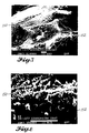
- FIGS. 1-4 show an unsealed cobalt conversion coating formed by a 20 minute immersion in a typical cobalt coating solution.
- FIGS. 5-8 show an unsealed cobalt conversion coating formed by a 30 minute immersion in a typical cobalt coating solution.
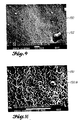
- FIGS. 9-12 show an unsealed cobalt conversion coating formed by a 50 minute immersion in a typical cobalt coating solution.
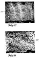
- FIGS. 13-16 show an unsealed cobalt conversion coating formed by a 60 minute immersion in a typical cobalt coating solution. There were only minor differences in oxide coating thickness between these immersion times. This suggests that at any given bath operating temperature, the oxide structure becomes self limiting.
- FIGS. 17-20 show surface views and fracture views of a sealed cobalt conversion coating.
- FIG. 1 is a photomicrograph at X10,000 magnification of a test panel showing a cobalt conversion coating 130 of the invention.
- the photomicrograph is a top view, from an elevated angle, of the upper surface of oxide coating 130.
- the top of oxide coating 130 is porous and looks like a layer of chow mein noodles.
- the porosity of oxide coating 130 gives excellent paint adhesion results.
- This test panel was immersed in a cobalt conversion coating solution for 20 minutes.
- the white bar is a length of 1 micron.
- FIG. 2 is a photomicrograph at X50,000 magnification of the test panel of FIG. 1.
- the photomicrograph is a top view, from an elevated angle, of the upper surface of oxide coating 130.
- FIG. 2 is a close-up, at higher magnification, of a small area of FIG. 1.
- the white bar is a length of 1 micron.
- FIG. 3 is a photomicrograph at X10,000 magnification of a test panel showing a side view of a fractured cross section of a cobalt conversion coating 130 of the invention.
- the fractured cross section of the aluminum substrate of the test panel is indicated by reference numeral 132.
- This test panel was immersed in a coating bath for 20 minutes. To make the photomicrograph, the test panel was bent and broken off to expose a cross section of oxide coating 130.
- the white bar is a length of 1 micron.
- FIG. 4 is a photomicrograph at X50,000 magnification of the test panel of FIG. 3 showing a side view of a fractured cross section of cobalt conversion coating 130 of the invention.
- FIG. 4 is a close-up, at higher magnification, of a small area of FIG. 3.
- the aluminum substrate of the test panel is indicated by reference numeral 132.
- the white bar is a length of 1 micron.
- Oxide coating 130 has a vertical thickness of about 0.12-0.14 micron.
- FIG. 5 is a photomicrograph at X10,000 magnification of another test panel showing another cobalt conversion coating 150 of the invention.
- the photomicrograph is a top view, from an elevated angle, of the upper surface of oxide coating 150.
- the top of oxide coating 150 is porous and looks like a layer of chow mein noodles.
- This test panel was immersed in a cobalt conversion coating solution for 30 minutes.
- the white bar is a length of 1 micron.
- FIG. 6 is a photomicrograph at X50,000 magnification of the test panel of FIG. 5.
- the photomicrograph is a top view, from an elevated angle, of the upper surface of oxide coating 150.
- FIG. 6 is a close-up, at higher magnification, of a small area of FIG. 5.
- the white bar is a length of 1 micron.
- FIG. 7 is a photomicrograph at X10,000 magnification of a test panel showing a side view of a fractured cross section of cobalt conversion coating 150 of the invention.
- the aluminum substrate of the test panel is indicated by reference numeral 152.
- This test panel was immersed in a coating bath for 30 minutes. To make the photomicrograph, the test panel was bent and broken off to expose a cross section of oxide coating 150.
- the white bar is a length of 1 micron.
- FIG. 8 is a photomicrograph at X50,000 magnification of the test panel of FIG. 7 showing a side view of a fractured cross section of cobalt conversion coating 150 of the invention.
- FIG. 8 is a close-up, at higher magnification, of a small area of FIG. 7.
- the aluminum substrate of the test panel is indicated by reference numeral 152.
- the white bar is a length of 1 micron.
- Oxide coating 150 has a vertical thickness of about 0.12-0.14 micron.
- FIG. 9 is a photomicrograph at X10,000 magnification of a test panel showing a cobalt conversion coating 190 of the invention.
- the photomicrograph is a top view, from an elevated angle, of the upper surface of oxide coating 190.
- the top of oxide coating 190 is porous and looks like a layer of chow mein noodles.
- This test panel was immersed in a cobalt conversion coating solution for 50 minutes.
- the oblong object indicated by reference numeral 192 is an impurity, believed to be a piece of oxidized material, on top of oxide coating 190.
- the white bar is a length of 1 micron.
- FIG. 10 is a photomicrograph at X50,000 magnification of the test panel of FIG. 9.
- the photomicrograph is a top view, from an elevated angle, of the upper surface of oxide coating 190.
- FIG. 10 is a close-up, at higher magnification, of a small area of FIG. 9.
- the roundish object indicated by reference numeral 192a is an unidentified impurity on top of oxide coating 190.
- the white bar is a length of 1 micron.
- FIG. 11 is a photomicrograph at X10,000 magnification of a test panel showing a side view of a fractured cross section of a cobalt conversion coating 190 of the invention.
- the fractured cross section of the aluminum substrate of the test panel is indicated by reference numeral 194.
- This test panel was immersed in a coating bath for 50 minutes. To make the photomicrograph, the test panel was bent and broken off to expose a cross section of oxide coating 190.
- the white bar is a length of 1 micron.
- FIG. 12 is a photomicrograph at X50,000 magnification of the test panel of FIG. 11 showing a side view of a fractured cross section of cobalt conversion coating 190 of the invention.
- FIG. 12 is a close-up, at higher magnification, of a small area of FIG. 11.
- the aluminum substrate of the test panel is indicated by reference numeral 194.
- the white bar is a length of 1 micron.
- Oxide coating 190 has a vertical thickness of about 0.12-0.14 micron.
- FIG. 13 is a photomicrograph at X10,000 magnification of another test panel showing a cobalt conversion coating 230 of the invention.
- the photomicrograph is a top view, from an elevated angle, of the upper surface of oxide coating 230.
- the top of oxide coating 230 is porous and looks like a layer of chow mein noodles.
- This test panel was immersed in a cobalt conversion coating solution for 60 minutes.
- the white bar is a length of 1 micron.
- FIG. 14 is a photomicrograph at X50,000 magnification of the test panel of FIG. 13.
- the photomicrograph is a top view, from an elevated angle, of the upper surface of oxide coating 230.
- FIG. 14 is a close-up, at higher magnification, of a small area of FIG. 13.
- the white bar is a length of 1 micron.
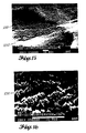
- FIG. 15 is a photomicrograph at X10,000 magnification of a test panel showing a side view of a fractured cross section of cobalt conversion coating 230 of the invention.
- the aluminum substrate of the test panel is indicated by reference numeral 232.
- This test panel was immersed in the coating bath for 60 minutes. To make the photomicrograph, the test panel was bent and broken off to expose a cross section of oxide coating 230.
- the white bar is a length of 1 micron.
- FIG. 16 is a photomicrograph at X50,000 magnification of the test panel of FIG. 15 showing a side view of a fractured cross section of cobalt conversion coating 230 of the invention.
- FIG. 16 is a close-up, at higher magnification, of a small area of FIG. 15.
- the white bar is a length of 1 micron.
- Oxide coating 150 has a vertical thickness of about 0.12-0.14 micron.
- FIG. 17 is a photomicrograph at X10,000 magnification of another test panel showing a sealed cobalt conversion coating 270 of the invention.
- the photomicrograph is a top view, from an elevated angle, of the upper surface of sealed oxide coating 270.
- This test panel was immersed in a sealing solution for 20 minutes.
- Sealed oxide coating 270 is not as porous as an unsealed oxide coating, the pores of the oxide coating being partially filled by hydration as a result of immersion in a sealing solution.
- the partial sealing of the oxide coating gives reduced paint adhesion results, but excellent corrosion resistance performance.
- the whitish areas identified by reference numeral 274 are believed to be impurities from the sealing solution.
- the white bar is a length of 1 micron.
- FIG. 18 is a photomicrograph at X50,000 magnification of the test panel of FIG. 17.
- the photomicrograph is a top view, from an elevated angle, of the upper surface of sealed oxide coating 270.
- FIG. 18 is a close-up, at higher magnification, of a small area of FIG. 17.
- Sealed oxide coating 270 is not as porous as an unsealed oxide coating, the pores of the oxide coating being partially filled by hydration as a result of immersion in a sealing solution.
- the white bar is a length of 1 micron.
- FIG. 19 is a photomicrograph at X10,000 magnification of a test panel showing a side view of a fractured cross section of sealed cobalt conversion coating 270 of the invention.
- the aluminum substrate of the test panel is indicated by reference numeral 272. This test panel was immersed in the sealing bath for 20 minutes. To make the photomicrograph, the test panel was bent and broken off to expose a cross section of oxide coating 270.
- the white bar is a length of 1 micron.
- FIG. 20 is a photomicrograph at X50,000 magnification of the test panel of FIG. 19 showing a side view of a fractured cross section of sealed cobalt conversion coating 270 of the invention.
- FIG. 20 is a close-up, at higher magnification, of a small area of FIG. 19.
- the white bar is a length of 1 micron.
- Sealed oxide coating 270 has a vertical thickness of about 0.12-0.14 micron.
- the first class is a cobalt conversion coating consisting of an oxide structure in unsealed condition and suitable for use in service where paint adhesion is especially important.
- the second class is a cobalt conversion coating consisting of an oxide structure in sealed condition and suitable for use in service where bare metal corrosion resistance performance is desired.
- cobalt coordination complexes are formed where the portion of the complex which includes the ligand (the bracketed portion in equations (1)-(5)) is negatively charged, i.e., (8) [Co(NO 2 ) 6 ] 3- and the complete complex is (9) Me 3 [Co(NO 2 ) 6 ] where Me corresponds to Na, K, or Li (alkali metal ions).
- This cobalt nitrite complex bath chemistry (equation (1)) has a distinct advantage over the previously described cobalt hexammine complex chemistry (equation (6)) in that pH control of the cobalt hexanitrite complex bath is not required.
- cobalt-III hexanitrite complexes are capable of forming oxide structures on aluminum substrates.
- the oxidizing ability of the cobalt-III hexanitrite complex is believed to be responsible for the formation of the observed oxide films (which I refer to as "cobalt conversion coatings") on aluminum substrates.
- the formation of oxide structures has been confirmed by instrumental analysis (Auger analysis and electron microscopy) of the coating.
- the photomicrographs in FIGS. 1-20 illustrate the appearance of the cobalt conversion coating of the invention.
- cobalt salts and metal nitrite salts are operable for cobalt complexing.
- cobalt-II salts which are operable in water solution are: cobalt nitrate, Co(NO 3 ) 2 ⁇ 6H 2 O; cobalt chloride, CoCl 2 ⁇ 6H 2 O; cobaltous sulfate, CoSO 4 ; cobaltous acetate, Co(CH 3 COO) 2 ⁇ 4H 2 O; and cobaltous basic carbonate, 2CoCO 3 ⁇ Co(OH) 2 ⁇ H 2 O.
- a nitrite salt such as NaNO 2 , KNO 2 , or LiNO 2 .
- cobalt-II salts may be used if they possess a minimum solubility in water or in a water solution containing a metal nitrite salt.
- the minimum solubility needed is 25 grams per 100 ml of water at 20°C (68°F) or 25 grams per 100 ml of water solution containing a metal nitrite salt at 20°C (68°F).
- the preferred reactants are Co(NO 3 ) 2 ⁇ 6H 2 O and NaNO 2 , since cobalt nitrite complexes formed with potassium or lithium nitrite are of limited solubility and will eventually drop out of an aqueous solution.
- a preferred chemical additive is an oxidizer, preferably hydrogen peroxide, H 2 O 2 .
- the function of the oxidizer is to oxidize the cobalt-II ions in solution to cobalt-III ions. Care must be taken that an excess amount of chemical oxidizer is not used because an excess would have the undesired effect of oxidizing the nitrite ions in solution to nitrate ions.
- the stream of air flowing into the tank functions as an oxidizer, so the presence of hydrogen peroxide is not essential for operability.
- the hydrogen peroxide increases the rate of oxidation of the cobalt-II ions in solution to cobalt-III ions and therefore is useful for commercial practice of the invention in that the solution becomes operational in a shorter period of time.
- reaction accelerator chemical such as sodium bromide (NaBr) or sodium iodide (NaI) may be added to the solution.
- NaBr sodium bromide
- NaI sodium iodide
- the reaction accelerator was found to have the effect of accelerating the formation of the oxide conversion coatings on aluminum alloy substrates as compared to solutions of cobalt-III hexanitrite complexes which did not contain this additive. The presence of the accelerator is not essential for operability. The accelerator increases the rate of formation of the oxide conversion coatings on aluminum alloys and therefore is useful for commercial practice of the invention.
- the preferred chemical reactants and additives are: Cobalt nitrate Co(N0 3 ) 2 ⁇ 6H 2 O Sodium nitrite NaNO 2 Hydrogen peroxide (oxidizer) H 2 O 2 Sodium iodide (accelerator) NaI
- the concentration of dissolved cobalt-II salt used may be from about 0.03 moles per liter (0.1 moles per gallon) of final solution up to the saturation limit of the cobalt-II salt employed.
- the concentration of dissolved metal nitrite salt may be from about 0.16 to 3.2 moles per liter (0.6 to 12 moles per gallon) of final solution.
- the concentration of oxidizer, such as hydrogen peroxide may be from complete omission up to about 0.1 moles per liter (0.5 moles per gallon) of final solution. As stated above, an excess amount of hydrogen peroxide has undesired effects.
- the concentration of accelerator salt, such as NaI, may be from complete omission up to the solubility limit of the accelerator in the solution.
- the pH of the bath may be from about 7.0 to 7.2.
- the temperature of the bath may be from about 20 °C (68°F) to 66°C (150°F); below 38°C (100°F coating formation is very slow; above 66°C (150°F) gradual decomposition of the cobalt-III hexanitrite complex occurs.
- the immersion time may be from about 3 minutes to 60 minutes.
- the cobalt conversion coating should be applied after all trimming and fabrication have been completed. Parts, where solution entrapment is possible, should not be subjected to immersion alkaline cleaning or immersion deoxidizing; manual cleaning and manual deoxidizing procedures should be used to obtain water break-free surfaces before applying cobalt conversion treatment.
- a water break-free surface is a surface which maintains a continuous water film for a period of at least 30 seconds after having been sprayed or immersion rinsed in clean water at a temperature below 38°C (100°F).
- Vapor degrease may be performed in accordance with Boeing Process Specification BAC 5408, emulsion clean in accordance with Boeing Process Specification BAC 5763, or solvent clean in accordance with Boeing Process Specification BAC 5750 if parts are greasy or oily. Parts with open faying surfaces or spot-welded joints where solution entrapment is possible should be immersed in cold water (or in hot and cold water) for 2 minutes after precleaning.
- Alkaline clean and rinse may be performed in accordance with Boeing Process Specification BAC 5744 or Boeing Process Specification BAC 5749 except for parts with open faying surfaces or spot welded joints, in which case, rinsing should be for at least 10 minutes using agitation with multiple immersions (a minimum of four times) followed by manual spray rinsing as required to prevent solution entrapment.
- Deoxidize and rinse may be performed in accordance with Boeing Process Specification BAC 5765 except for parts where solution entrapment is possible, which parts may be rinsed using the method described above under "Alkaline Cleaning". Castings may be deoxidized by either of the following methods:
- Example 1 The formulation of Example 1, with a molar ratio of nitrite salt to cobalt salt of about 12 to 1, is useful for producing oxide coatings exhibiting high paint adhesion in unsealed condition.
- Example 2 also having a molar ratio of nitrite salt to cobalt salt of about 12 to 1, is useful for producing oxide coatings possessing high paint adhesion properties in unsealed condition.
- any 2-valent soluble cobalt salt may be reacted with any soluble nitrite salt to form 3-valent cobalt hexanitrite complexes.
- this type of complexing is not restricted to nitrites only.
- cyanide salts were used (i.e., sodium cyanide, NaCN) to form hexacyano complexes of the type shown below (10) Me 3 [Co(CN) 6 ] and have yielded satisfactory conversion coatings on aluminum alloys.
- cyanide complexes will not be used because of environmental considerations.
- Nickel sulfate NiS0 4 ⁇ 6H 2 0 (hexahydrate) 40.2 (152) gm (about 0.15 (0.58) moles) 38.0-42.0 (144-159) gm Ammonium nitrate, NH 4 NO 3 30.1 (114) gm (about 0.375 (1.42) moles) 27.7-32.0 (105-121) gm Manganese acetate, Mn(CH 3 COO) 2 ⁇ 4H 2 O 20 (76) gm (about 0.082 (0.31) moles) 18-22 (68-84) gm Operating temperature 85 ⁇ 3°C (185 ⁇ 5° F)
- the immersion time in the sealing solution may be about 10-30 minutes, with 15 minutes being preferred.
- the sealing solution is believed to seal the cobalt conversion coating by a hydration mechanism.
- FIGS. 17-20, particularly FIG. 18, show a sealed cobalt conversion coating 270.
- Other sealing solutions which may be employed are as follows:
- Solutions 1-3 are not preferred because they lose their effectiveness over a period of time, whereas the solution in Example 4 has a long life.
- a continuous operating temperature range of the cobalt conversion tank of 49-60°C (120-140°F) yields optimum results with respect to coating performance on aluminum alloy substrates.
- Optimum paint adhesion is obtained when the tank is operated at or near 49°C (120°F), while optimum corrosion resistance performance is given at 60°C (140°F) in combination with the subsequent seal process.
- Immersion times in the cobalt conversion tank have an effect on the oxide coating thickness as measured by the coating weight (in unsealed condition) ranging from 430 to 646 mg/m 2 (40 to 60 mg/ft 2 ).
- An optimum immersion time for maximum paint adhesion is 15 minutes and for maximum corrosion resistance performance is 30 minutes.
- Salt spray corrosion resistance of cobalt conversion coatings produced by the above processes varies over a wide range, depending on reactant selection, immersion times, and bath operating temperatures. Preferred results are obtained when the formulation of Example 1 is utilized at immersion times of 30 minutes. In this way, sealed oxide coatings have been produced with 168 hrs. of salt spray corrosion resistance when sealed with the seal solution as described herein and tested in accordance with ASTM B117.
- Paint adhesion tests were conducted using aircraft paints qualified to Boeing Material Specification BMS 10-11 (a highly crosslinked epoxy primer) and BMS 10-60 (a highly crosslinked urethane topcoat).
- BMS 10-11 a highly crosslinked epoxy primer
- BMS 10-60 a highly crosslinked urethane topcoat
- corrosion resistance and paint adhesion performance properties have an inverse relationship. In general, where corrosion resistance is at a maximum, paint adhesion is at a minimum, and vice versa.
- the optional post-conversion step consisting of immersion into a heated solution (at 85 ⁇ 3°C (185 ⁇ 5°F)) of NiS0 4 /NH 4 NO 3 /Mn-acetate minimizes this problem by maintaining sufficient paint adhesion values while maintaining high corrosion resistance properties.
- ESCA electron spectroscopy for chemical analysis (also known as XPS or X-ray photoelectron spectroscopy).)
- the cobalt conversion coating consists of a mixture of oxides, namely, aluminum oxide, Al 2 O 3 , as the largest volume percent, and cobalt oxides, CoO, Co 3 O 4 , and Co 2 O 3 .
- the term "largest volume percent” means that the volume of this oxide exceeds the volume of any other oxide which is present, but the term “largest volume percent” does not necessarily imply that the volume of this oxide is more than 50 volume percent.
- the data further shows that in the lower portion of the oxide coating (that is, next to the aluminum substrate), the largest volume percent is Al 2 O 3 .
- the middle portion of the oxide coating is a mixture of CoO, Co 3 O 4 , Co 2 O 3 , and Al 2 O 3 .
- the data shows that in the top portion of the oxide coating, the largest volume percent is a mixture of Co 3 O 4 and Co 2 O 3 .
- FIGS. 1-4 show a cobalt conversion coating 130 (in the unsealed condition) formed by a 20 minute immersion in a typical cobalt conversion coating solution.
- FIGS. 5-8 show a cobalt conversion coating 150 (in the unsealed condition) formed by a 30 minute immersion in a typical cobalt conversion coating solution.
- FIGS. 9-12 show a cobalt conversion coating 190 (in the unsealed condition) formed by a 50 minute immersion in a typical cobalt conversion coating solution.
- FIGS. 1-4 show a cobalt conversion coating 130 (in the unsealed condition) formed by a 20 minute immersion in a typical cobalt conversion coating solution.
- FIGS. 5-8 show a cobalt conversion coating 150 (in the unsealed condition) formed by a 30 minute immersion in a typical cobalt conversion coating solution.
- FIGS. 9-12 show a cobalt conversion coating 190 (in the unsealed condition) formed by a 50 minute immersion in a typical cobalt
- FIGS. 13-16 show a cobalt conversion coating 230 (in the unsealed condition) formed by a 60 minute immersion in a typical cobalt conversion coating solution. Comparing FIGS. 1-4, FIGS. 5-8, FIGS. 9-12, and FIGS. 13-16, there does not appear to be any significant structural difference between coating 130, coating 150, coating 190, and coating 230. This suggests that at any given bath operating temperature, the oxide coating becomes self limiting.
- the top surface of the cobalt conversion coating as shown in FIGS. 1, 2, 5, 6, 9, 10, 13, and 14 is porous and bears a resemblance to chow mein noodles. This oxide structure provides appreciable surface area and porosity for good paint adhesion.
- FIGS. 17-20 show sealed cobalt conversion coating 270.
- the cobalt conversion coating was formed on the substrate and then the coating was partially sealed by immersion in a sealing solution.
- FIG. 18 shows the partially sealed structure of coating 270.
- Sealed oxide coating 270 is not as porous as an unsealed oxide coating, the pores of the oxide coating being partially filled by hydration as a result of immersion in a sealing solution. The partial sealing of the oxide coating gives reduced paint adhesion results, but excellent corrosion resistance performance.
Landscapes
- Chemical & Material Sciences (AREA)
- General Chemical & Material Sciences (AREA)
- Chemical Kinetics & Catalysis (AREA)
- Engineering & Computer Science (AREA)
- Materials Engineering (AREA)
- Mechanical Engineering (AREA)
- Metallurgy (AREA)
- Organic Chemistry (AREA)
- Chemical Treatment Of Metals (AREA)
- Chemically Coating (AREA)
Abstract
Description
- This environmental-quality invention is in the field of chemical conversion coatings formed on metal substrates, for example, on aluminum substrates. More particularly, one aspect of the invention is a new type of oxide coating (which I refer to as a "cobalt conversion coating") which is chemically formed on metal substrates. The invention enhances the quality of the environment of mankind by contributing to the maintenance of air and water quality.
- In general, chemical conversion coatings are formed chemically by causing the surface of the metal to be "converted" into a tightly adherent coating, all or part of which consists of an oxidized form of the substrate metal. Chemical conversion coatings can provide high corrosion resistance as well as strong bonding affinity for paint. The industrial application of paint (organic finishes) to metals generally requires the use of a chemical conversion coating, particularly when the performance demands are high.
- Although aluminum protects itself against corrosion by forming a natural oxide coating, the protection is not complete. In the presence of moisture and electrolytes, aluminum alloys, particularly the high-copper 2000-series aluminum alloys, such as alloy 2024-T3, corrode much more rapidly than pure aluminum.
- In general, there are two types of processes for treating aluminum to form a beneficial conversion coating. The first is by anodic oxidation (anodization) in which the aluminum component is immersed in a chemical bath, such as a chromic or sulfuric acid bath, and an electric current is passed through the aluminum component and the chemical bath. The resulting conversion coating on the surface of the aluminum component offers resistance to corrosion and a bonding surface for organic finishes.
- The second type of process is by chemically producing a conversion coating, which is commonly referred to as a chemical conversion coating, by subjecting the aluminum component to a chemical solution, such as a chromic acid solution, but without using an electric current in the process. The chemical solution may be applied by immersion application, by manual application, or by spray application. The resulting conversion coating on the surface of the aluminum component offers resistance to corrosion and a bonding surface for organic finishes. The present invention relates to this second type of process for producing chemical conversion coatings. The chemical solution may be applied by immersion application, by various types of manual application, or by spray application.
- One widely-used chromic acid process for forming chemical conversion coatings on aluminum substrates is described in various embodiments in Ostrander et al. U.S. Patent 2,796,370 and Ostrander et al. U.S. Patent 2,796,371, in military process specification MIL-C-5541, and in Boeing Process Specification BAC 5719. These chromic acid chemical conversion baths contain hexavalent chromium, fluorides, and cyanides, all of which present significant environmental as well as health and safety problems. The constituents of a typical chromic acid conversion bath, such as ALODINE 1200, are as follows: CrO3 - "chromic acid" (hexavalent chromium); NaF - sodium fluoride; KBF4 - potassium tetrafluoroborate; K2ZrF6 - potassium hexafluorozirconate; K3Fe(CN)6 - potassium ferricyanide; and, HNO3 - nitric acid (for pH control).
- Many aluminum structural parts, as well as Cd plated, Zn plated, Zn-Ni plated, and steel parts, throughout the aircraft and aerospace industry are currently being treated using this chromic acid process technology. Chromic acid conversion films, as formed on aluminum substrates, meet a 168 hours corrosion resistance criterion, but they primarily serve as a surface substrate for paint adhesion. Because of their relative thinness and low coating weights (430-1615 mg/m2 (40-150 milligrams/ft2)), chromic acid conversion coatings do not cause a fatigue life reduction in the aluminum structure.
- However, environmental regulations in the United States, particularly in California, and in other countries are drastically reducing the allowed levels of hexavalent chromium compounds in effluents and emissions from metal finishing processes. Accordingly, chemical conversion processes employing hexavalent chromium compounds must be replaced. The present invention, which does not employ hexavalent chromium compounds, is intended to replace the previously used chromic acid process for forming conversion coatings on aluminum substrates.
- The earlier European patent application EP-A-458,020 (priority date May 17, 1990), state of the art and prejudicial for novelty pursuant to Article 54(3) and (4) EPC, discloses a process for forming a cobalt conversion coating on a metal substrate using a soluble cobalt-III hexavalent complex, such as [Co(NH3)6]-X3, wherein X is selected from the group comprising Cl, Br, NO3, CN, SCN, 1/3PO4, ½SO4, C2H3O2, and ½CO3.
- The process according to the invention for forming an oxide film cobalt conversion coating exhibiting corrosion resistance and paint adhesion properties on a metal substrate comprises the steps of:
- (a) providing an oxide film forming cobalt conversion solution comprising an aqueous reaction solution comprising a soluble cobalt-III hexacoordinated complex in the form of a soluble cobalt-III hexanitrite complex, the concentration of said cobalt-III hexacoordinated complex being from 0.03 moles per liter (0.1 mole per gallon) of solution to the saturation limit of said cobalt-III hexacoordinated complex; and
- (b) contacting said metal substrate with said solution for a sufficient amount of time to oxidise the surface of said substrate, whereby said oxide film cobalt conversion coating is formed, thereby imparting corrosion resistance and paint adhesion to said substrate.
- The substrate may be aluminum or aluminum alloy, as well as magnesium and its alloys, Cd plated substrates and Zn plated substrates. The cobalt-III hexanitrite complex may be present in the form of Me3[Co(NO2)6], wherein Me corresponds to Na, K or Li.
- Another aspect of the invention is a chemical conversion coating solution for producing an oxide film cobalt conversion coating on a metal substrate, said solution comprising an aqueous solution of a soluble cobalt-III hexacoordinated complex in the form of a soluble cobalt-III hexanitrite complex, the concentration of said cobalt-III hexacoordinated complex being from 0.03 moles per liter (0.1 mole per gallon) of solution to the saturation limit of said cobalt-III hexacoordinated complex, said reaction solution is obtainable by reacting a cobalt-II salt with a metal nitrite salt, wherein the concentration of said cobalt-II salt is from 0.03 moles per liter (0.1 moles per gallon) of final solution to the saturation limit of the cobalt-II salt employed and the concentration of said metal nitrite salt is from 0.16 moles per liter (0.6 moles per gallon) of final solution, and an oxidizer to oxidize the cobalt-II ions to cobalt-III ions and a reaction accelerator, selected from the group comprising sodium iodide, Na I, or sodium bromide, Na Br, to accelerate the formation of said cobalt conversion coating on said substrate. The substrate may be aluminum or aluminum alloy, as well as magnesium and its alloys, Cd plated substrates, and Zn plated substrates. The cobalt-III hexacoordinated complex may be present in the form of Me3[Co(NO2)6] wherein Me corresponds to Na, K, or Li.
- The cobalt conversion solution may be prepared by a bath makeup sequence including the steps of: (a) dissolving a metal nitrite salt; (b) dissolving an accelerator such as NaI; (c) dissolving a cobalt-II salt; and (d) then adding an oxidizer such as H2O2.
- The invention relates also to the obtained coated article exhibiting corrosion resistance and paint adhesion properties, the article including: (a) an aluminium or aluminium alloy substrate; and (b) a cobalt conversion coating formed on the substrate, the cobalt conversion coating including aluminum oxide Al2O3 as the largest volume percent, and one or more cobalt oxides from the group consisting of CoO, Co3O4, and Co2O3, wherein the cobalt conversion coating has a thickness of 0.12 to 0.14 µm.
- The figures herein are photomicrographs of images produced by a scanning electron microscope (SEM) of coatings on aluminum alloy test panels. FIGS. 1-20 are photomicrographs (scanning electron microscope operated at 20 KV) of aluminum alloy 2024-T3 test panels with cobalt conversion coatings made by the invention. FIGS. 1-16 show surface views and fracture views of unsealed cobalt conversion coatings. The photomicrographs of FIGS. 1-16 reveal a highly porous surface oxide (unsealed cobalt conversion coatings) with a thickness range of about 0.12 to 0.14 micron (1200 to 1400 Angstroms). FIGS. 1-4 show an unsealed cobalt conversion coating formed by a 20 minute immersion in a typical cobalt coating solution. FIGS. 5-8 show an unsealed cobalt conversion coating formed by a 30 minute immersion in a typical cobalt coating solution. FIGS. 9-12 show an unsealed cobalt conversion coating formed by a 50 minute immersion in a typical cobalt coating solution. FIGS. 13-16 show an unsealed cobalt conversion coating formed by a 60 minute immersion in a typical cobalt coating solution. There were only minor differences in oxide coating thickness between these immersion times. This suggests that at any given bath operating temperature, the oxide structure becomes self limiting. FIGS. 17-20 show surface views and fracture views of a sealed cobalt conversion coating.
- FIG. 1 is a photomicrograph at X10,000 magnification of a test panel showing a
cobalt conversion coating 130 of the invention. The photomicrograph is a top view, from an elevated angle, of the upper surface ofoxide coating 130. The top ofoxide coating 130 is porous and looks like a layer of chow mein noodles. The porosity ofoxide coating 130 gives excellent paint adhesion results. This test panel was immersed in a cobalt conversion coating solution for 20 minutes. The white bar is a length of 1 micron. - FIG. 2 is a photomicrograph at X50,000 magnification of the test panel of FIG. 1. The photomicrograph is a top view, from an elevated angle, of the upper surface of
oxide coating 130. FIG. 2 is a close-up, at higher magnification, of a small area of FIG. 1. The white bar is a length of 1 micron. - FIG. 3 is a photomicrograph at X10,000 magnification of a test panel showing a side view of a fractured cross section of a
cobalt conversion coating 130 of the invention. The fractured cross section of the aluminum substrate of the test panel is indicated byreference numeral 132. This test panel was immersed in a coating bath for 20 minutes. To make the photomicrograph, the test panel was bent and broken off to expose a cross section ofoxide coating 130. The white bar is a length of 1 micron. - FIG. 4 is a photomicrograph at X50,000 magnification of the test panel of FIG. 3 showing a side view of a fractured cross section of
cobalt conversion coating 130 of the invention. FIG. 4 is a close-up, at higher magnification, of a small area of FIG. 3. The aluminum substrate of the test panel is indicated byreference numeral 132. The white bar is a length of 1 micron.Oxide coating 130 has a vertical thickness of about 0.12-0.14 micron. - FIG. 5 is a photomicrograph at X10,000 magnification of another test panel showing another
cobalt conversion coating 150 of the invention. The photomicrograph is a top view, from an elevated angle, of the upper surface ofoxide coating 150. The top ofoxide coating 150 is porous and looks like a layer of chow mein noodles. This test panel was immersed in a cobalt conversion coating solution for 30 minutes. The white bar is a length of 1 micron. - FIG. 6 is a photomicrograph at X50,000 magnification of the test panel of FIG. 5. The photomicrograph is a top view, from an elevated angle, of the upper surface of
oxide coating 150. FIG. 6 is a close-up, at higher magnification, of a small area of FIG. 5. The white bar is a length of 1 micron. - FIG. 7 is a photomicrograph at X10,000 magnification of a test panel showing a side view of a fractured cross section of
cobalt conversion coating 150 of the invention. The aluminum substrate of the test panel is indicated byreference numeral 152. This test panel was immersed in a coating bath for 30 minutes. To make the photomicrograph, the test panel was bent and broken off to expose a cross section ofoxide coating 150. The white bar is a length of 1 micron. - FIG. 8 is a photomicrograph at X50,000 magnification of the test panel of FIG. 7 showing a side view of a fractured cross section of
cobalt conversion coating 150 of the invention. FIG. 8 is a close-up, at higher magnification, of a small area of FIG. 7. The aluminum substrate of the test panel is indicated byreference numeral 152. The white bar is a length of 1 micron.Oxide coating 150 has a vertical thickness of about 0.12-0.14 micron. - FIG. 9 is a photomicrograph at X10,000 magnification of a test panel showing a
cobalt conversion coating 190 of the invention. The photomicrograph is a top view, from an elevated angle, of the upper surface ofoxide coating 190. The top ofoxide coating 190 is porous and looks like a layer of chow mein noodles. This test panel was immersed in a cobalt conversion coating solution for 50 minutes. The oblong object indicated byreference numeral 192 is an impurity, believed to be a piece of oxidized material, on top ofoxide coating 190. The white bar is a length of 1 micron. - FIG. 10 is a photomicrograph at X50,000 magnification of the test panel of FIG. 9. The photomicrograph is a top view, from an elevated angle, of the upper surface of
oxide coating 190. FIG. 10 is a close-up, at higher magnification, of a small area of FIG. 9. The roundish object indicated by reference numeral 192a is an unidentified impurity on top ofoxide coating 190. The white bar is a length of 1 micron. - FIG. 11 is a photomicrograph at X10,000 magnification of a test panel showing a side view of a fractured cross section of a
cobalt conversion coating 190 of the invention. The fractured cross section of the aluminum substrate of the test panel is indicated byreference numeral 194. This test panel was immersed in a coating bath for 50 minutes. To make the photomicrograph, the test panel was bent and broken off to expose a cross section ofoxide coating 190. The white bar is a length of 1 micron. - FIG. 12 is a photomicrograph at X50,000 magnification of the test panel of FIG. 11 showing a side view of a fractured cross section of
cobalt conversion coating 190 of the invention. FIG. 12 is a close-up, at higher magnification, of a small area of FIG. 11. The aluminum substrate of the test panel is indicated byreference numeral 194. The white bar is a length of 1 micron.Oxide coating 190 has a vertical thickness of about 0.12-0.14 micron. - FIG. 13 is a photomicrograph at X10,000 magnification of another test panel showing a
cobalt conversion coating 230 of the invention. The photomicrograph is a top view, from an elevated angle, of the upper surface ofoxide coating 230. The top ofoxide coating 230 is porous and looks like a layer of chow mein noodles. This test panel was immersed in a cobalt conversion coating solution for 60 minutes. The white bar is a length of 1 micron. - FIG. 14 is a photomicrograph at X50,000 magnification of the test panel of FIG. 13. The photomicrograph is a top view, from an elevated angle, of the upper surface of
oxide coating 230. FIG. 14 is a close-up, at higher magnification, of a small area of FIG. 13. The white bar is a length of 1 micron. - FIG. 15 is a photomicrograph at X10,000 magnification of a test panel showing a side view of a fractured cross section of
cobalt conversion coating 230 of the invention. The aluminum substrate of the test panel is indicated byreference numeral 232. This test panel was immersed in the coating bath for 60 minutes. To make the photomicrograph, the test panel was bent and broken off to expose a cross section ofoxide coating 230. The white bar is a length of 1 micron. - FIG. 16 is a photomicrograph at X50,000 magnification of the test panel of FIG. 15 showing a side view of a fractured cross section of
cobalt conversion coating 230 of the invention. FIG. 16 is a close-up, at higher magnification, of a small area of FIG. 15. The white bar is a length of 1 micron.Oxide coating 150 has a vertical thickness of about 0.12-0.14 micron. - FIG. 17 is a photomicrograph at X10,000 magnification of another test panel showing a sealed
cobalt conversion coating 270 of the invention. The photomicrograph is a top view, from an elevated angle, of the upper surface of sealedoxide coating 270. This test panel was immersed in a sealing solution for 20 minutes.Sealed oxide coating 270 is not as porous as an unsealed oxide coating, the pores of the oxide coating being partially filled by hydration as a result of immersion in a sealing solution. The partial sealing of the oxide coating gives reduced paint adhesion results, but excellent corrosion resistance performance. The whitish areas identified byreference numeral 274 are believed to be impurities from the sealing solution. The white bar is a length of 1 micron. - FIG. 18 is a photomicrograph at X50,000 magnification of the test panel of FIG. 17. The photomicrograph is a top view, from an elevated angle, of the upper surface of sealed
oxide coating 270. FIG. 18 is a close-up, at higher magnification, of a small area of FIG. 17.Sealed oxide coating 270 is not as porous as an unsealed oxide coating, the pores of the oxide coating being partially filled by hydration as a result of immersion in a sealing solution. The white bar is a length of 1 micron. - FIG. 19 is a photomicrograph at X10,000 magnification of a test panel showing a side view of a fractured cross section of sealed
cobalt conversion coating 270 of the invention. The aluminum substrate of the test panel is indicated byreference numeral 272. This test panel was immersed in the sealing bath for 20 minutes. To make the photomicrograph, the test panel was bent and broken off to expose a cross section ofoxide coating 270. The white bar is a length of 1 micron. - FIG. 20 is a photomicrograph at X50,000 magnification of the test panel of FIG. 19 showing a side view of a fractured cross section of sealed
cobalt conversion coating 270 of the invention. FIG. 20 is a close-up, at higher magnification, of a small area of FIG. 19. The white bar is a length of 1 micron.Sealed oxide coating 270 has a vertical thickness of about 0.12-0.14 micron. - I have invented two classes of cobalt conversion coatings. The first class is a cobalt conversion coating consisting of an oxide structure in unsealed condition and suitable for use in service where paint adhesion is especially important. The second class is a cobalt conversion coating consisting of an oxide structure in sealed condition and suitable for use in service where bare metal corrosion resistance performance is desired.
- A considerable amount of empirical research was conducted in order to arrive at the present invention. A variety of multivalent compounds was investigated, used either by themselves or in combination with alkalies, acids, or fluorides. Among these compounds were vanadates, molybdates, cerates, ferrates and a variety of borates. While film deposition of compounds containing these elements on aluminum alloy substrates has been achieved, none afforded any appreciable corrosion protection nor paint adhesion.
- A significant increase in corrosion protection was observed, however, when aluminum substrates were immersed in aqueous solutions of simple cobalt-II (Co2+) salts heated to 180°F. This led to an investigation of a number of cobalt-II and cobalt-III (Co3+) reactions, in particular as described in EP-A-458,020
- When 2-valent cobalt salts are dissolved into an aqueous solution of MeNO2 (where Me = Na, K, or Li) (alkali metal ions), in the presence of an oxidizing agent, such as H2O2, then 3-valent cobalt nitrite complexes are formed:


- These 3-valent cobalt nitrite complexes were found to produce brightly iridescent oxide coatings on aluminum substrates.
- The chemistry described in EP-A-458020 involved the chemistry of an aqueous solution containing a cobalt-II salt such as CoX2 (where X2 = Cl2, Br2, (NO3)2, (CN)2, (SCN)2, PO4, SO4, (CH3COO)2, CO3) and the corresponding ammonium salt NH4X in the presence of ammonium hydroxide (ammonia) to form a cobalt-III hexammine coordination complex, for example:

- It should be noted that the above cobalt hexammine chemistry in equation (6) involves a cobalt coordination complex where the portion of the complex which includes the ligand (the bracketed portion in equation (6)) is positively charged, i.e.,
(7) [Co(NH3)6]3+
- In the cobalt hexanitrite chemistry subsequently developed and described herein, cobalt coordination complexes are formed where the portion of the complex which includes the ligand (the bracketed portion in equations (1)-(5)) is negatively charged, i.e.,
(8) [Co(NO2)6]3-
and the complete complex is
(9) Me3[Co(NO2)6]
where Me corresponds to Na, K, or Li (alkali metal ions). - This cobalt nitrite complex bath chemistry (equation (1)) has a distinct advantage over the previously described cobalt hexammine complex chemistry (equation (6)) in that pH control of the cobalt hexanitrite complex bath is not required.
- It was discovered that when aluminum alloy substrates (such as alloy 2024-T3) are immersed in an aqueous solution containing the cobalt-III nitrite complexes above, bright iridescent coatings are formed on the aluminum alloy, which give excellent corrosion resistance properties.
- It is surprising that cobalt-III hexanitrite complexes are capable of forming oxide structures on aluminum substrates. The oxidizing ability of the cobalt-III hexanitrite complex is believed to be responsible for the formation of the observed oxide films (which I refer to as "cobalt conversion coatings") on aluminum substrates. The formation of oxide structures has been confirmed by instrumental analysis (Auger analysis and electron microscopy) of the coating. The photomicrographs in FIGS. 1-20 illustrate the appearance of the cobalt conversion coating of the invention.
- Initial bath formulations were made up using Co(NO3)2·6H2O and NaNO2. Reaction quantities were used in accordance with stoichiometric amounts as shown in equation (2) above.
- It became apparent during experimentation with this initial formulation that a number of parameters are important from the standpoint of bath chemistry and uniform formation of oxide coating films. These parameters are: chemical reactant selection; chemical reactant concentrations; bath makeup sequence; temperature; and immersion time. It should be noted that pH control is not a factor.
- Regarding reactant selection, a wide variety of cobalt salts and metal nitrite salts are operable for cobalt complexing. Among the cobalt-II salts which are operable in water solution are: cobalt nitrate, Co(NO3)2·6H2O; cobalt chloride, CoCl2·6H2O; cobaltous sulfate, CoSO4; cobaltous acetate, Co(CH3COO)2·4H2O; and cobaltous basic carbonate, 2CoCO3·Co(OH)2·H2O. Each of the foregoing cobalt-II salts may be reacted with a nitrite salt such as NaNO2, KNO2, or LiNO2.
- Furthermore, other cobalt-II salts may be used if they possess a minimum solubility in water or in a water solution containing a metal nitrite salt. The minimum solubility needed is 25 grams per 100 ml of water at 20°C (68°F) or 25 grams per 100 ml of water solution containing a metal nitrite salt at 20°C (68°F).
- It may also be noted that for aluminum and aluminum alloys the preferred reactants are Co(NO3)2·6H2O and NaNO2, since cobalt nitrite complexes formed with potassium or lithium nitrite are of limited solubility and will eventually drop out of an aqueous solution.
- A preferred chemical additive is an oxidizer, preferably hydrogen peroxide, H2O2. The function of the oxidizer is to oxidize the cobalt-II ions in solution to cobalt-III ions. Care must be taken that an excess amount of chemical oxidizer is not used because an excess would have the undesired effect of oxidizing the nitrite ions in solution to nitrate ions. The stream of air flowing into the tank functions as an oxidizer, so the presence of hydrogen peroxide is not essential for operability. The hydrogen peroxide increases the rate of oxidation of the cobalt-II ions in solution to cobalt-III ions and therefore is useful for commercial practice of the invention in that the solution becomes operational in a shorter period of time.
- Furthermore, it may also be noted that a reaction accelerator chemical such as sodium bromide (NaBr) or sodium iodide (NaI) may be added to the solution. (NaI is preferred.) The reaction accelerator was found to have the effect of accelerating the formation of the oxide conversion coatings on aluminum alloy substrates as compared to solutions of cobalt-III hexanitrite complexes which did not contain this additive. The presence of the accelerator is not essential for operability. The accelerator increases the rate of formation of the oxide conversion coatings on aluminum alloys and therefore is useful for commercial practice of the invention.
- Thus the preferred chemical reactants and additives are:
Cobalt nitrate Co(N03)2·6H2O Sodium nitrite NaNO2 Hydrogen peroxide (oxidizer) H2O2 Sodium iodide (accelerator) NaI - With respect to chemical reactant concentrations, the concentration of dissolved cobalt-II salt used may be from about 0.03 moles per liter (0.1 moles per gallon) of final solution up to the saturation limit of the cobalt-II salt employed. The concentration of dissolved metal nitrite salt may be from about 0.16 to 3.2 moles per liter (0.6 to 12 moles per gallon) of final solution. The concentration of oxidizer, such as hydrogen peroxide, may be from complete omission up to about 0.1 moles per liter (0.5 moles per gallon) of final solution. As stated above, an excess amount of hydrogen peroxide has undesired effects. The concentration of accelerator salt, such as NaI, may be from complete omission up to the solubility limit of the accelerator in the solution. The pH of the bath may be from about 7.0 to 7.2. The temperature of the bath may be from about 20 °C (68°F) to 66°C (150°F); below 38°C (100°F coating formation is very slow; above 66°C (150°F) gradual decomposition of the cobalt-III hexanitrite complex occurs. The immersion time may be from about 3 minutes to 60 minutes.
-
- 1. A stainless steel tank fitted with air agitation plumbing and heating coils is filled to 3/4 with deionized water at a temperature of 20°C (68°F) to 32°C (90°F). Air agitation is commenced to a gentle bubble. (The tank-may be equipped with a filter unit to remove any solid impurities (dust, aluminum silt, etc.) during processing.)
- 2. A quantity of nitrite salt (NaNO2 is preferred) is added and completely dissolved. Stainless steel baskets may be used to hold the nitrite salt granules suspended in the water while dissolving. The preferred concentration of nitrite salt is about 1.0 moles per liter (about 3.6 moles per gallon) of final solution. The amount used is based on the mole ratio of nitrite salt to cobalt salt which will produce an oxide coating exhibiting high paint adhesion properties. The preferred molar ratio of nitrite salt to cobalt salt is about 12 to 1.
- 3. A quantity of sodium iodide (the conversion coating reaction accelerator) may now be added. The concentration of this additive may be from no addition up to the solubility limit, however the preferred quantity is 860-1080 grams per liter (80-100 gm per gallon) of final solution.
- 4. The cobalt-II salt is now added and dissolved. The preferred concentration is about 0.08 moles per liter (0.3 moles per gallon) of final solution. This concentration of the cobalt salt, when added to a solution already containing 1.0 moles per liter (3.6 moles per gallon) of nitrite salt, achieves the preferred molar ratio of nitrite salt to cobalt salt of 12 to 1. Moderate air agitation is maintained.
- 5. A quantity of hydrogen peroxide H2O2 is now slowly added. The preferred amount is 0.08 (0.3) to 0.13 (0.5) moles of H2O2 (7.8 (30) to 13 (50)ml of H2O2 (30 volume %)) per liter (gallon) of final solution. The tank is filled to the final volume with deionized water. Air agitation of this solution is maintained for 12-16 hours at a temperature of 20-32°C (68-90°F) and then the solution is heated to preferably 49±3°C (120 ± 5°F). The use of H2O2 is preferred for fast and consistent cobalt-III hexanitrite complex formation. The solution is now ready for operation.
- 6. Optionally, a second stainless steel tank (to be used for a coating seal step) is prepared with air agitation plumbing and heating coils and is filled 3/4 with deionized water. This post-cobalt conversion coating step serves as an oxide coating sealer to promote corrosion resistance performance. The tank is heated to 82±3°C (180 ± 5°F) with air agitation.
- 7. A quantity of ammonium nitrate, NH4NO3, is added to the seal tank and dissolved. The preferred amount is 30.1 grams (0.38 moles) per liter) (114 gm (1.42 moles) per gallon) of final solution. Stir as necessary to dissolve.
- 8. A quantity of nickel sulfate, NiSO4·6H2O, and a quantity of manganese acetate, Mn(CH3COO)2·4H2O, are added to the seal tank and dissolved. The preferred amount of nickel sulfate is 40.2 grams (0.15 moles) per liter (152 gm (0.58 moles) per gallon) of final solution. The preferred amount of manganese acetate is 20 grams (0.08 moles) per liter (76 gm (0.31 moles) per gallon) of final solution. Stir as necessary to dissolve.
- 9. The seal tank is then filled to final volume with deionized water. No further air agitation is needed.
- The preferred overall processing sequences may be summarized as follows:
-
- (1) PRECLEAN IF REQUIRED
- (2) MASK AND RACK AS REQUIRED
- (3) ALKALINE CLEAN AND RINSE
- (4) DEOXIDIZE AND RINSE
- (5) FORM OXIDE COATING - 15 MINUTES AT 52±3°C (125 ± 5°F)
- (6) IMMERSION RINSE - 60°C (140°F), 5 MINUTES MINIMUM
- (7) DRY - 60°C (140°F) MAXIMUM
-
- (1) PRECLEAN IF REQUIRED
- (2) MASK AND RACK AS REQUIRED
- (3) ALKALINE CLEAN AND RINSE
- (4) DEOXIDIZE AND RINSE
- (5) FORM OXIDE COATING - 30 MINUTES AT 52±3°C (125 ± 5°F)
- (6) IMMERSION RINSE - 60°C (140°F), 5 MINUTES MINIMUM
- (7) SEAL AS REQUIRED
- (8) RINSE - ROOM TEMPERATURE, 3 MINUTES MINIMUM
- (9) DRY - 60°C (140°F) MAXIMUM
- The cobalt conversion coating should be applied after all trimming and fabrication have been completed. Parts, where solution entrapment is possible, should not be subjected to immersion alkaline cleaning or immersion deoxidizing; manual cleaning and manual deoxidizing procedures should be used to obtain water break-free surfaces before applying cobalt conversion treatment. A water break-free surface is a surface which maintains a continuous water film for a period of at least 30 seconds after having been sprayed or immersion rinsed in clean water at a temperature below 38°C (100°F).
- Thorough rinsing and draining throughout processing is necessary as each solution should be completely removed to avoid interference with the performance of the next solution in the sequence. Parts should be processed from one step to the next without delay and without allowing the parts to dry. When it is necessary to handle wet parts, wear clean latex rubber gloves. After conversion coating, handle dry parts only with clean fabric gloves. For processing systems which require part clamping, the number and size of contact points should be kept to a minimum as necessary for adequate mechanical support.
- Vapor degrease may be performed in accordance with Boeing Process Specification BAC 5408, emulsion clean in accordance with Boeing Process Specification BAC 5763, or solvent clean in accordance with Boeing Process Specification BAC 5750 if parts are greasy or oily. Parts with open faying surfaces or spot-welded joints where solution entrapment is possible should be immersed in cold water (or in hot and cold water) for 2 minutes after precleaning.
- Areas which do not require cobalt conversion coatings should be masked with maskants. Dissimilar metal inserts (except chromium, nickel or cobalt alloy or plating, CRES, or titanium) and non-aluminum coated plasma flame sprayed area should be masked off.
- Alkaline clean and rinse may be performed in accordance with Boeing Process Specification BAC 5744 or Boeing Process Specification BAC 5749 except for parts with open faying surfaces or spot welded joints, in which case, rinsing should be for at least 10 minutes using agitation with multiple immersions (a minimum of four times) followed by manual spray rinsing as required to prevent solution entrapment.
- Deoxidize and rinse may be performed in accordance with Boeing Process Specification BAC 5765 except for parts where solution entrapment is possible, which parts may be rinsed using the method described above under "Alkaline Cleaning". Castings may be deoxidized by either of the following methods:
- a. Deoxidize in accordance with Boeing Process Specification BAC 5765, Solution 37, 38 or 39.
- b. Dry abrasive blast castings in accordance with Boeing Process Specification BAC 5748, Type II, Class 1 and rinse.
- Examples of specific solution formulations within the scope of the invention are as follows:
-
Component Make-Up Per Liter (Gallon) Of Final Solution Control Limits Cobalt(ous) nitrate, Co(NO3)2·6H20 (hexahydrate) 22 (85) gm (about 0.077 (0.29) mole) 20-25 g/liter (75-95 gm/gal) Sodium nitrite, NaNO2 63.9 (242) gm (about 0.93 (3.51) moles) 60.0-65.0 g/liter (227-246 gm/gal) Sodium Iodide, NaI 24 (90) gm (about 0.16 (0.60) moles) 22-26 g/liter (83-99 gm/gal) Hydrogen peroxide, H2O2 (30 vol. %) 7.8-13 (30-50) ml (about 0.08-0.13 (0.3-0.5) moles of H202) Water balance Temperature 49±3°C (120 ± 5° F) pH 7.0 - 7.2 - The formulation of Example 1, with a molar ratio of nitrite salt to cobalt salt of about 12 to 1, is useful for producing oxide coatings exhibiting high paint adhesion in unsealed condition.
-
Component Make-Up Per Liter (Gallon) Of Final Solution Control Limits Cobalt(ous) chloride, CoCl2·6H20 (hexahydrate) 18 (69) gm (about 0.077 (0.29) mole) Sodium nitrite, NaN02 63.9 (242) gm (about 0.927 (3.51) moles) Sodium iodide, NaI 24 (90) gm (about 0.16 (0.60) moles) Hydrogen peroxide, H2O2 (30 vol. %) 7.9-13 (30-50) ml (about 0..8-0.13 (0.3-0.5) moles of H2O2) Water balance Temperature 49-66°C (120-150°F) pH 7.0 - 7.2 - The formulation of Example 2, also having a molar ratio of nitrite salt to cobalt salt of about 12 to 1, is useful for producing oxide coatings possessing high paint adhesion properties in unsealed condition.
-
Component Make-Up Per Liter (Gallon) Of Final Solution Control Limits Cobalt acetate, Co(CH3COO)2·4H20 19 (73) gm (about 0.077 (0.29) moles) Sodium nitrite, NaNO2 63.9 (242) gm (about 0.927 (3.51) moles) Sodium iodide, NaI (accelerator) 24 (90) gm (about 0.16 (0.60) moles) Hydrogen peroxide, H2O2 (30 vol. %) 7.9-13 (30-50) ml (about 0.08-0.13 (0.3-0.5) moles of H2O2) Water balance Temperature 49-66°C (120-150°F) pH 7.0 - 7.2 - It should be noted that in all of the above examples hydrogen peroxide H2O2 (30 vol. %) is employed to convert the 2-valent cobalt salt into the 3-valent cobalt hexanitrite complex. While air bubbling (aeration) of the solution alone will convert a sufficient quantity of cobalt-II salt to cobalt-III complex, the procedure will be time consuming and complete conversion may never be obtained.
- In principle, any 2-valent soluble cobalt salt may be reacted with any soluble nitrite salt to form 3-valent cobalt hexanitrite complexes. Furthermore, this type of complexing, as shown in formula (8) above, is not restricted to nitrites only. For research purposes, cyanide salts were used (i.e., sodium cyanide, NaCN) to form hexacyano complexes of the type shown below
(10) Me3[Co(CN)6]
and have yielded satisfactory conversion coatings on aluminum alloys. However, cyanide complexes will not be used because of environmental considerations. - As mentioned above, in order to produce cobalt conversion coatings with maximum corrosion resistance performance (168 hrs. salt spray corrosion resistance, when tested in accordance with ASTM B117) it is necessary to subject the cobalt conversion coating to a sealing step. For this purpose, a number of sealing solutions were found to be useful, however, the sealing solution formulation below is preferred.
-
Component Make-Up Per Liter (Gallon) Of Final Solution Control Limits Nickel sulfate, NiS04·6H20 (hexahydrate) 40.2 (152) gm (about 0.15 (0.58) moles) 38.0-42.0 (144-159) gm Ammonium nitrate, NH4NO3 30.1 (114) gm (about 0.375 (1.42) moles) 27.7-32.0 (105-121) gm Manganese acetate, Mn(CH3COO)2·4H2O 20 (76) gm (about 0.082 (0.31) moles) 18-22 (68-84) gm Operating temperature 85±3°C (185 ± 5° F) - The immersion time in the sealing solution may be about 10-30 minutes, with 15 minutes being preferred. The sealing solution is believed to seal the cobalt conversion coating by a hydration mechanism. FIGS. 17-20, particularly FIG. 18, show a sealed
cobalt conversion coating 270. Other sealing solutions which may be employed are as follows: - Solution 1:
- Boric acid, H3BO3, (50 gm/gal) 13 g/liter. Cobalt sulfate, CoSO4·7H20, (25 gm/gal) 6.6 g/liter. Ammonium acetate, CH3COONH4, (25 gm/gal) 6.6 g/liter.
- Solution 2:
- Boric acid, H3BO3, (30 gm/gal) 7.9 g/liter Sodium borate, Na2B4O7, (30 gm/gal) 7.9 g/liter Sodium nitrite, NaNO2, (30 gm/gal) 7.9 g/liter Ammonium vanadate, NH4VO3, (5 gm/gal) 1.3 g/liter
- Solution 3:
- Cobalt sulfate, CoSO4·7H2O, (25 gm/gal) 6.6 g/liter Ammonium vanadate, NH4VO3, (5 gm/gal) 1.3 g/liter Boric acid, H3BO3, (50 gm/gal) 13 g/liter
- Solutions 1-3 are not preferred because they lose their effectiveness over a period of time, whereas the solution in Example 4 has a long life.
- The two process parameters of solution temperature and immersion time have been found to be important as relating to cobalt conversion coating performance.
- A continuous operating temperature range of the cobalt conversion tank of 49-60°C (120-140°F) yields optimum results with respect to coating performance on aluminum alloy substrates. Optimum paint adhesion is obtained when the tank is operated at or near 49°C (120°F), while optimum corrosion resistance performance is given at 60°C (140°F) in combination with the subsequent seal process. Immersion times in the cobalt conversion tank have an effect on the oxide coating thickness as measured by the coating weight (in unsealed condition) ranging from 430 to 646 mg/m2 (40 to 60 mg/ft2). An optimum immersion time for maximum paint adhesion is 15 minutes and for maximum corrosion resistance performance is 30 minutes.
- Salt spray corrosion resistance of cobalt conversion coatings produced by the above processes varies over a wide range, depending on reactant selection, immersion times, and bath operating temperatures. Preferred results are obtained when the formulation of Example 1 is utilized at immersion times of 30 minutes. In this way, sealed oxide coatings have been produced with 168 hrs. of salt spray corrosion resistance when sealed with the seal solution as described herein and tested in accordance with ASTM B117.
- Paint adhesion tests were conducted using aircraft paints qualified to Boeing Material Specification BMS 10-11 (a highly crosslinked epoxy primer) and BMS 10-60 (a highly crosslinked urethane topcoat). General trends observed with the present cobalt conversion coatings are consistent with conventional chromic acid conversion coatings, i.e., corrosion resistance and paint adhesion performance properties have an inverse relationship. In general, where corrosion resistance is at a maximum, paint adhesion is at a minimum, and vice versa.
- However, the optional post-conversion step consisting of immersion into a heated solution (at 85±3°C (185 ± 5°F)) of NiS04/NH4NO3/Mn-acetate minimizes this problem by maintaining sufficient paint adhesion values while maintaining high corrosion resistance properties.
- ESCA surface analysis, using a Perkin-Elmer Model 550 surface analyzer, and Auger oxide profiles, using the same machine (in a different operating mode), have been performed in order to characterize the cobalt conversion coatings of the invention. (ESCA = electron spectroscopy for chemical analysis (also known as XPS or X-ray photoelectron spectroscopy).)
- These analyses show that the cobalt conversion coating consists of a mixture of oxides, namely, aluminum oxide, Al2O3, as the largest volume percent, and cobalt oxides, CoO, Co3O4, and Co2O3. The term "largest volume percent" means that the volume of this oxide exceeds the volume of any other oxide which is present, but the term "largest volume percent" does not necessarily imply that the volume of this oxide is more than 50 volume percent.
- The data further shows that in the lower portion of the oxide coating (that is, next to the aluminum substrate), the largest volume percent is Al2O3. The middle portion of the oxide coating is a mixture of CoO, Co3O4, Co2O3, and Al2O3. And the data shows that in the top portion of the oxide coating, the largest volume percent is a mixture of Co3O4 and Co2O3.
- Additional characterization of the cobalt conversion coatings of the invention may be found above in the "Brief Description Of The Drawings", in FIGS. 1-20, and in the descriptions of FIGS. 1-20. FIGS. 1-4 show a cobalt conversion coating 130 (in the unsealed condition) formed by a 20 minute immersion in a typical cobalt conversion coating solution. FIGS. 5-8 show a cobalt conversion coating 150 (in the unsealed condition) formed by a 30 minute immersion in a typical cobalt conversion coating solution. FIGS. 9-12 show a cobalt conversion coating 190 (in the unsealed condition) formed by a 50 minute immersion in a typical cobalt conversion coating solution. FIGS. 13-16 show a cobalt conversion coating 230 (in the unsealed condition) formed by a 60 minute immersion in a typical cobalt conversion coating solution. Comparing FIGS. 1-4, FIGS. 5-8, FIGS. 9-12, and FIGS. 13-16, there does not appear to be any significant structural difference between
coating 130, coating 150, coating 190, andcoating 230. This suggests that at any given bath operating temperature, the oxide coating becomes self limiting. The top surface of the cobalt conversion coating, as shown in FIGS. 1, 2, 5, 6, 9, 10, 13, and 14 is porous and bears a resemblance to chow mein noodles. This oxide structure provides appreciable surface area and porosity for good paint adhesion. - FIGS. 17-20 show sealed
cobalt conversion coating 270. The cobalt conversion coating was formed on the substrate and then the coating was partially sealed by immersion in a sealing solution. In particular, FIG. 18 shows the partially sealed structure ofcoating 270.Sealed oxide coating 270 is not as porous as an unsealed oxide coating, the pores of the oxide coating being partially filled by hydration as a result of immersion in a sealing solution. The partial sealing of the oxide coating gives reduced paint adhesion results, but excellent corrosion resistance performance. - The above examples illustrate producing cobalt conversion coatings by immersion application. The same principles apply to producing the conversion coating by manual application and by spray application.
- The patents, specifications, and other publications referenced above are incorporated herein by reference.
Claims (39)
- A process for forming an oxide film cobalt conversion coating exhibiting corrosion resistance and paint adhesion properties on a metal substrate, said process comprising the steps of:(a) providing an oxide film forming cobalt conversion solution comprising an aqueous reaction solution comprisiing a soluble cobalt-III hexacoordinated complex in the form of a soluble cobalt-III hexanitrite complex, the concentration of said cobalt-III hexacoordinated complex being from 0.03 moles per liter (0.1 mole per gallon) of solution to the saturation limit of said cobalt-III hexacoordinated complex; and(b) contacting said metal substrate with said solution for a sufficient amount of time to oxidise the surface of said substrate, whereby said oxide film cobalt conversion coating is formed, thereby imparting corrosion resistance and paint adhesion to said substrate.
- The process of claim 1, wherein said cobalt-III hexacoordinated complex is present in the form of Me3[Co(NO2)6] wherein Me is one or more selected from the group comprising Na, K, and Li.
- The process of claims 1 or 2, wherein said cobalt conversion solution has a pH of 7.0 to 7.2.
- The process of claims 1-3, wherein said cobalt conversion solution has a temperature of 20°C (68°F) to 66°C (150°F).
- The process of claims 1-4, wherein said substrate is contacted with said cobalt conversion solution for a time of 3 minutes to 60 minutes.
- The process of claims 1-5, wherein said substrate is magnesium, magnesium alloy, a Cd plated substrate, or a Zn plated substrate.
- The process of claims 1-6, wherein said substrate is aluminum or aluminum alloy.
- The process of claims 1-7, wherein said cobalt conversion solution comprises an aqueous solution prepared by reacting a cobalt-II salt with a metal nitrite salt, wherein the concentration of said cobalt-II salt is from 0.03 moles per liter (0.1 moles per gallon) of final solution to the saturation limit of the cobalt-II salt employed and the concentration of said metal nitrite salt is from 0.16 to 3.2 moles per liter (0.6 to 12 moles per gallon) of final solution.
- The process of claim 8, wherein said cobalt-II salt is CoX2, wherein X2 is one or more selected from the group comprising (NO3)2, Cl2, (CH3COO)2 (acetate), SO4, Br2, (CN)2, (SCN)2, or CO3.
- The process of claims 8 or 9, wherein said metal nitrite salt is MeNO2 wherein Me is one or more selected from the group comprising Na, K or Li.
- The process of claims 8-10, wherein an oxidizer is added to said cobalt conversion solution to oxidize the cobalt-II ions in solution to cobalt-III ions.
- The process of claim 11, wherein said oxidizer is hydrogen peroxide, H2O2.
- The process of claim 12, wherein hydrogen peroxide, H2O2, in the amount of 0.08 to 0.13 moles per liter (0.3 to 0.5 moles per gallon) of final solution is added to said cobalt conversion solution.
- The process of claims 8-13, wherein a reaction accelerator, selected from the group comprising sodium iodide, NaI, and sodium bromide, NaBr, is added to said cobalt conversion solution to accelerate the formation of said cobalt conversion coating on said substrate.
- The process of claim 14, wherein sodium iodide, NaI, in the amount of 22 to 26 grams per liter (83 to 99 grams per gallon) of final solution is added to said cobalt conversion solution.
- The process of claims 8-15, wherein said cobalt conversion solution is prepared by a bath makeup sequence comprising:(a) adding and dissolving said metal nitrite salt;(b) then adding and dissolving a reaction accelerator;(c) then adding and dissolving said cobalt-II salt; and(d) then adding an oxidizer to the solution.
- The process of claims 8-16, wherein said solution is prepared by reacting said cobalt-II salt with said metal nitrite salt, wherein the molar ratio of said metal nitrite salt to cobalt salt is about 6 to 1 to 14 to 1.
- The process of claims 8-17, comprising the additional step of contacting said coated substrate with an aqueous sealing solution comprising nickel sulfate, NiSO4.6H2O, ammonium nitrate, NH4NO3, and manganese acetate, Mn(CH3COO)2.4H2O.
- The process of claims 1-18, wherein a cobalt conversion solution is provided comprising an aqueous solution prepared by reacting cobalt nitrate, Co(NO3)2.6H2O, with sodium nitrite, NaNO2, wherein the concentration of said cobalt nitrate is from 20 to 25 grams per liter (75 to 95 grams per gallon) of final solution and the concentration of said sodium nitrite is from 60 to 65 grams per liter (227 to 246 grams per gallon) of final solution.
- The process of claim 19, wherein said cobalt conversion solution is prepared by a batch makeup sequence comprising:(a) adding and dissolving said sodium nitrite;(b) then adding and dissolving sodium iodide, NaI;(c) the adding and dissolving said cobalt nitrate; and(d) then adding said hydrogen peroxide, H2O2, to the solution.
- The process of claim 19 or 20, wherein said cobalt conversion solution has a temperature of 49 ± 3°C (120 ± 5°F).
- The process of claims 19-21, wherein said substrate is contacted with said cobalt conversion solution for a time of 15 minutes to 30 minutes.
- A chemical conversion coating solution for producing an oxide film cobalt conversion coating on a metal substrate, said solution comprising an aqueous reaction solution of a soluble cobalt-III hexacoordinated complex in the form of a soluble cobalt-III hexanitrite complex, the concentration of said cobalt-III hexacoordinated complex being from 0.03 moles per liter (0.1 mole per gallon) of solution to the saturation limit of said cobalt-III hexacoordinated complex, said reaction solution is obtainable by reacting a cobalt-II salt with a metal nitrite salt, wherein the concentration of said cobalt-II salt is from 0.03 moles per liter (0.1 moles per gallon) of final solution to the saturation limit of the cobalt-II salt employed and the concentration of said metal nitrite salt is from 0.16 moles per liter (0.6 moles per gallon) of final solution, and an oxidizer to oxidize the cobalt-II ions to cobalt-III ions and a reaction accelerator, selected from the group comprising sodium iodide, NaI, or sodium bromide, NaBr, to accelerate the formation of said cobalt conversion coating on said substrate.
- The solution of claim 23, wherein said cobalt-III hexacoordinated complex is present in the form of Me3[Co(No2)6] wherein Me is one or more selected from the group consisting of Na, K, and Li.
- The solution of claim 23 or 24, wherein said cobalt-II salt is CoX2 wherein X2 is one or more selected from the group comprising (NO3)2, Cl2, (CH3COO)2 (acetate), SO4, Br2, (CN)2, (SCN)2, or CO3.
- The solution of claim 23-25, wherein said metal nitrite salt is MeNO2 wherein Me is one or more selected from the group comprising Na, K, and Li.
- The solution of claim 23-26, wherein said oxidizer is hydrogen peroxide, H2O2.
- The solution of claims 23-27, wherein said cobalt conversion solution is prepared by a bath makeup sequence comprising the steps of:(a) adding and dissolving said metal nitrite salt;(b) then adding and dissolving said reaction accelerator;(c) then adding and dissolving said cobalt-II salt; and(d) then adding said oxidizer to the solution.
- The solution of claims 23-28, wherein said solution is prepared by reacting said cobalt-II salt with said metal nitrite salt, wherein the molar ratio of nitrite salt to cobalt salt is 6 to 1 to 14 to 1.
- The solution of claims 23-29, wherein said solution has a pH of 7.0 to 7.2.
- The solution of claims 23-30, wherein said solution has a temperature of 20°C (68°F) to 66°C (150°F).
- The solution of claims 23-31, wherein said substrate is magnesium, magnesium alloy, a Cd plated substrate, or a Zn plated substrate.
- The solution of claims 23-32, wherein said substrate is aluminum or aluminum alloy.
- The solution of claims 25-33, wherein said cobalt-III hexanitrite complex is sodium cobalt-III hexanitrite complex, said cobalt-II salt is cobalt-II nitrate, said metal nitrite salt is sodium nitrite, and said solution has a temperature of 49 ± 3°C (120 ± 5°F).
- A coated article obtained in a process of claims 1-22 or by using the solution of claim 23-34, whereby the coating has a thickness of 0.12 to 0.14 µm
- A coated article of claim 35 exhibiting corrosion resistance and paint adhesion properties, said article comprising:(a) an aluminum or aluminum alloy substrate; and(b) a cobalt conversion coating formed on said substrate, said cobalt conversion coating comprising aluminum oxide Al2O3 as the largest volume percent, and one or more cobalt oxides from the group consisting of CoO, Co3O4, and Co2O3.wherein said cobalt conversion coating has a thickness of 0.12 to 0.14 µm.
- The article of claim 36, wherein(a) in the portion of said cobalt conversion coating adjacent said substrate, the largest volume percent of said coating consists essentially of Al2O3;(b) in the top portion of said cobalt conversion coating, the largest volume percent of said coating consists essentially of a mixture of Co3O4 and Co2O3; and(c) in the portion of said cobalt conversion coating therebetween, said coating consists essentially of a mixture of CoO, Co3O4, Co2O3, and Al2O3.
- The article of claims 37, wherein the top of said cobalt conversion coating (150,190,230) is porous and has the appearance of chow mein noodles at X 10,000 magnification.
- The article of claims 37-38, wherein said cobalt conversion coating is sealed.
Applications Claiming Priority (2)
| Application Number | Priority Date | Filing Date | Title |
|---|---|---|---|
| US62113290A | 1990-11-30 | 1990-11-30 | |
| US621132 | 1990-11-30 |
Publications (3)
| Publication Number | Publication Date |
|---|---|
| EP0488430A2 EP0488430A2 (en) | 1992-06-03 |
| EP0488430A3 EP0488430A3 (en) | 1992-12-16 |
| EP0488430B1 true EP0488430B1 (en) | 1997-06-11 |
Family
ID=24488866
Family Applications (1)
| Application Number | Title | Priority Date | Filing Date |
|---|---|---|---|
| EP91202181A Expired - Lifetime EP0488430B1 (en) | 1990-11-30 | 1991-08-27 | Non-chromated cobalt conversion coating |
Country Status (13)
| Country | Link |
|---|---|
| EP (1) | EP0488430B1 (en) |
| JP (1) | JP3194607B2 (en) |
| AT (1) | ATE154401T1 (en) |
| AU (1) | AU650494B2 (en) |
| BR (1) | BR9105184A (en) |
| CA (1) | CA2056159C (en) |
| DE (1) | DE69126507T2 (en) |
| DK (1) | DK0488430T3 (en) |
| ES (1) | ES2104655T3 (en) |
| GR (1) | GR3024046T3 (en) |
| HK (1) | HK1006861A1 (en) |
| MX (1) | MX9102254A (en) |
| NZ (1) | NZ240779A (en) |
Families Citing this family (25)
| Publication number | Priority date | Publication date | Assignee | Title |
|---|---|---|---|---|
| US5468307A (en) * | 1990-05-17 | 1995-11-21 | Schriever; Matthias P. | Non-chromated oxide coating for aluminum substrates |
| US5472524A (en) * | 1990-05-17 | 1995-12-05 | The Boeing Company | Non-chromated cobalt conversion coating method and coated articles |
| US5551994A (en) * | 1990-05-17 | 1996-09-03 | The Boeing Company | Non-chromated oxide coating for aluminum substrates |
| US5411606A (en) * | 1990-05-17 | 1995-05-02 | The Boeing Company | Non-chromated oxide coating for aluminum substrates |
| CA2087473C (en) * | 1990-05-17 | 2001-10-16 | Matthias P. Schriever | Non-chromated oxide coating for aluminum substrates |
| US5298092A (en) * | 1990-05-17 | 1994-03-29 | The Boeing Company | Non-chromated oxide coating for aluminum substrates |
| ES2125231T3 (en) * | 1991-07-19 | 1999-03-01 | Boeing Co | NON-CHROME OXIDE COATINGS FOR ALUMINUM SUBSTRATES. |
| CN1138873C (en) * | 1992-06-25 | 2004-02-18 | 波音公司 | Non-chromated oxide coating for aluminum substrates |
| ES2171170T3 (en) | 1993-09-13 | 2002-09-01 | Commw Scient Ind Res Org | METAL TREATMENT THROUGH A CLEANING SOLUTION CONTAINING ION ACIDS FROM RARE LANDS. |
| AUPM621194A0 (en) * | 1994-06-10 | 1994-07-07 | Commonwealth Scientific And Industrial Research Organisation | Conversion coating and process for its formation |
| JP3655635B2 (en) | 1994-11-11 | 2005-06-02 | コモンウェルス・サイエンティフィック・アンド・インダストリアル・リサーチ・オーガナイゼーション | Method for imparting chemical conversion film to metal surface and solution therefor |
| GB9617416D0 (en) * | 1996-08-20 | 1996-10-02 | Minnesota Mining & Mfg | Thermal bleaching of infrared dyes |
| FR2752851B1 (en) * | 1996-09-02 | 1998-11-13 | Cfpi Ind | BATH AND METHOD FOR PHOSPHATION OF METAL SUBSTRATES, CONCENTRATE FOR THE PREPARATION OF THIS BATH AND METAL SUBSTRATES TREATED WITH THE BATH AND METHOD |
| US5873953A (en) * | 1996-12-26 | 1999-02-23 | The Boeing Company | Non-chromated oxide coating for aluminum substrates |
| ZA983867B (en) * | 1997-05-16 | 1998-11-13 | Henkel Corp | Lithium and vanadium containing sealing composition and process therewith |
| US6315823B1 (en) | 1998-05-15 | 2001-11-13 | Henkel Corporation | Lithium and vanadium containing sealing composition and process therewith |
| US6432225B1 (en) * | 1999-11-02 | 2002-08-13 | The Boeing Company | Non-chromated oxide coating for aluminum substrates |
| AUPQ633200A0 (en) | 2000-03-20 | 2000-04-15 | Commonwealth Scientific And Industrial Research Organisation | Process and solution for providing a conversion coating on a metallic surface I |
| AUPQ633300A0 (en) | 2000-03-20 | 2000-04-15 | Commonwealth Scientific And Industrial Research Organisation | Process and solution for providing a conversion coating on a metallic surface ii |
| US7235142B2 (en) | 2002-01-04 | 2007-06-26 | University Of Dayton | Non-toxic corrosion-protection rinses and seals based on cobalt |
| EP1472319A1 (en) | 2002-01-04 | 2004-11-03 | University Of Dayton | Non-toxic corrosion protection pigments based on cobalt |
| US7294211B2 (en) | 2002-01-04 | 2007-11-13 | University Of Dayton | Non-toxic corrosion-protection conversion coats based on cobalt |
| US6818313B2 (en) | 2002-07-24 | 2004-11-16 | University Of Dayton | Corrosion-inhibiting coating |
| US20040011252A1 (en) | 2003-01-13 | 2004-01-22 | Sturgill Jeffrey A. | Non-toxic corrosion-protection pigments based on manganese |
| JP4934984B2 (en) * | 2005-03-31 | 2012-05-23 | 大日本印刷株式会社 | Method for producing metal oxide film |
Family Cites Families (5)
| Publication number | Priority date | Publication date | Assignee | Title |
|---|---|---|---|---|
| US3905838A (en) * | 1974-04-10 | 1975-09-16 | Hikaru Ito | Bath for treating aluminum and aluminum alloys to form oxide film nonelectrolytically thereon and method for the treatment |
| US4381203A (en) * | 1981-11-27 | 1983-04-26 | Amchem Products, Inc. | Coating solutions for zinc surfaces |
| JPH0331484A (en) * | 1989-06-27 | 1991-02-12 | Nippon Parkerizing Co Ltd | Blackening treatment of zinc or zinc-based plating material |
| JPH03226584A (en) * | 1990-01-30 | 1991-10-07 | Nippon Parkerizing Co Ltd | Solution for surface-treating galvanized steel sheet and method therefor |
| US5298092A (en) * | 1990-05-17 | 1994-03-29 | The Boeing Company | Non-chromated oxide coating for aluminum substrates |
-
1991
- 1991-08-27 DE DE69126507T patent/DE69126507T2/en not_active Expired - Lifetime
- 1991-08-27 ES ES91202181T patent/ES2104655T3/en not_active Expired - Lifetime
- 1991-08-27 EP EP91202181A patent/EP0488430B1/en not_active Expired - Lifetime
- 1991-08-27 AT AT91202181T patent/ATE154401T1/en not_active IP Right Cessation
- 1991-08-27 DK DK91202181.3T patent/DK0488430T3/en active
- 1991-11-25 CA CA002056159A patent/CA2056159C/en not_active Expired - Lifetime
- 1991-11-27 AU AU88225/91A patent/AU650494B2/en not_active Ceased
- 1991-11-28 MX MX9102254A patent/MX9102254A/en not_active IP Right Cessation
- 1991-11-28 BR BR919105184A patent/BR9105184A/en not_active IP Right Cessation
- 1991-11-28 NZ NZ240779A patent/NZ240779A/en not_active IP Right Cessation
- 1991-11-29 JP JP31608191A patent/JP3194607B2/en not_active Expired - Lifetime
-
1997
- 1997-07-09 GR GR970401701T patent/GR3024046T3/en unknown
-
1998
- 1998-06-22 HK HK98105956A patent/HK1006861A1/en not_active IP Right Cessation
Also Published As
| Publication number | Publication date |
|---|---|
| EP0488430A3 (en) | 1992-12-16 |
| EP0488430A2 (en) | 1992-06-03 |
| DE69126507D1 (en) | 1997-07-17 |
| BR9105184A (en) | 1992-07-21 |
| HK1006861A1 (en) | 1999-03-19 |
| DK0488430T3 (en) | 1998-01-05 |
| JP3194607B2 (en) | 2001-07-30 |
| ES2104655T3 (en) | 1997-10-16 |
| GR3024046T3 (en) | 1997-10-31 |
| NZ240779A (en) | 1994-11-25 |
| CA2056159C (en) | 2001-07-03 |
| ATE154401T1 (en) | 1997-06-15 |
| AU8822591A (en) | 1992-06-04 |
| CA2056159A1 (en) | 1992-05-31 |
| AU650494B2 (en) | 1994-06-23 |
| DE69126507T2 (en) | 1997-09-25 |
| MX9102254A (en) | 1992-06-01 |
| JPH059745A (en) | 1993-01-19 |
Similar Documents
| Publication | Publication Date | Title |
|---|---|---|
| EP0488430B1 (en) | Non-chromated cobalt conversion coating | |
| EP0458020B1 (en) | Non-chromated oxide coating for aluminum substrates | |
| EP0776384B1 (en) | Improved non-chromated oxide coating for aluminium substrates | |
| US5472524A (en) | Non-chromated cobalt conversion coating method and coated articles | |
| EP0646187B1 (en) | Non-chromated oxide coating for aluminum substrates | |
| US5411606A (en) | Non-chromated oxide coating for aluminum substrates | |
| EP0523288B1 (en) | Non-chromated oxide coating for aluminum substrates | |
| US5873953A (en) | Non-chromated oxide coating for aluminum substrates | |
| EP1230424B1 (en) | Non-chromated oxide coating for aluminum substrates | |
| US5378293A (en) | Non-chromated oxide coating for aluminum substrates | |
| US5468307A (en) | Non-chromated oxide coating for aluminum substrates | |
| KR100327142B1 (en) | Method for forming cobalt conversion coating on metal substrate, chemical conversion coating solution and article manufactured by the above method | |
| KR100305009B1 (en) | Method for forming a non-chromate oxide coating for an aluminum substrate | |
| RU2130977C1 (en) | Method of forming cobalt oxide conversion coating and aqueous solution for preparing cobalt oxide conversion coating | |
| NZ245684A (en) | Solution and process for producing a cobalt conversion coating on a metal substrate |
Legal Events
| Date | Code | Title | Description |
|---|---|---|---|
| PUAI | Public reference made under article 153(3) epc to a published international application that has entered the european phase |
Free format text: ORIGINAL CODE: 0009012 |
|
| AK | Designated contracting states |
Kind code of ref document: A2 Designated state(s): AT BE CH DE DK ES FR GB GR IT LI LU NL SE |
|
| PUAL | Search report despatched |
Free format text: ORIGINAL CODE: 0009013 |
|
| AK | Designated contracting states |
Kind code of ref document: A3 Designated state(s): AT BE CH DE DK ES FR GB GR IT LI LU NL SE |
|
| 17P | Request for examination filed |
Effective date: 19930615 |
|
| 17Q | First examination report despatched |
Effective date: 19930719 |
|
| GRAG | Despatch of communication of intention to grant |
Free format text: ORIGINAL CODE: EPIDOS AGRA |
|
| GRAH | Despatch of communication of intention to grant a patent |
Free format text: ORIGINAL CODE: EPIDOS IGRA |
|
| GRAH | Despatch of communication of intention to grant a patent |
Free format text: ORIGINAL CODE: EPIDOS IGRA |
|
| GRAA | (expected) grant |
Free format text: ORIGINAL CODE: 0009210 |
|
| AK | Designated contracting states |
Kind code of ref document: B1 Designated state(s): AT BE CH DE DK ES FR GB GR IT LI LU NL SE |
|
| REF | Corresponds to: |
Ref document number: 154401 Country of ref document: AT Date of ref document: 19970615 Kind code of ref document: T |
|
| REG | Reference to a national code |
Ref country code: CH Ref legal event code: NV Representative=s name: ARNOLD & SIEDSMA AG Ref country code: CH Ref legal event code: EP |
|
| REF | Corresponds to: |
Ref document number: 69126507 Country of ref document: DE Date of ref document: 19970717 |
|
| REG | Reference to a national code |
Ref country code: GR Ref legal event code: FG4A Free format text: 3024046 |
|
| ET | Fr: translation filed | ||
| REG | Reference to a national code |
Ref country code: ES Ref legal event code: FG2A Ref document number: 2104655 Country of ref document: ES Kind code of ref document: T3 |
|
| REG | Reference to a national code |
Ref country code: DK Ref legal event code: T3 |
|
| PLBE | No opposition filed within time limit |
Free format text: ORIGINAL CODE: 0009261 |
|
| STAA | Information on the status of an ep patent application or granted ep patent |
Free format text: STATUS: NO OPPOSITION FILED WITHIN TIME LIMIT |
|
| 26N | No opposition filed | ||
| REG | Reference to a national code |
Ref country code: GB Ref legal event code: IF02 |
|
| PGFP | Annual fee paid to national office [announced via postgrant information from national office to epo] |
Ref country code: CH Payment date: 20100812 Year of fee payment: 20 Ref country code: ES Payment date: 20100915 Year of fee payment: 20 Ref country code: NL Payment date: 20100810 Year of fee payment: 20 |
|
| PGFP | Annual fee paid to national office [announced via postgrant information from national office to epo] |
Ref country code: SE Payment date: 20100812 Year of fee payment: 20 Ref country code: LU Payment date: 20100915 Year of fee payment: 20 Ref country code: IT Payment date: 20100823 Year of fee payment: 20 Ref country code: FR Payment date: 20100824 Year of fee payment: 20 Ref country code: DE Payment date: 20100825 Year of fee payment: 20 Ref country code: AT Payment date: 20100812 Year of fee payment: 20 |
|
| PGFP | Annual fee paid to national office [announced via postgrant information from national office to epo] |
Ref country code: GR Payment date: 20100719 Year of fee payment: 20 Ref country code: GB Payment date: 20100825 Year of fee payment: 20 |
|
| PGFP | Annual fee paid to national office [announced via postgrant information from national office to epo] |
Ref country code: DK Payment date: 20100812 Year of fee payment: 20 |
|
| PGFP | Annual fee paid to national office [announced via postgrant information from national office to epo] |
Ref country code: BE Payment date: 20100818 Year of fee payment: 20 |
|
| REG | Reference to a national code |
Ref country code: DE Ref legal event code: R071 Ref document number: 69126507 Country of ref document: DE |
|
| REG | Reference to a national code |
Ref country code: DE Ref legal event code: R071 Ref document number: 69126507 Country of ref document: DE |
|
| BE20 | Be: patent expired |
Owner name: THE *BOEING CY Effective date: 20110827 |
|
| REG | Reference to a national code |
Ref country code: CH Ref legal event code: PL |
|
| REG | Reference to a national code |
Ref country code: NL Ref legal event code: V4 Effective date: 20110827 |
|
| REG | Reference to a national code |
Ref country code: DK Ref legal event code: EUP |
|
| REG | Reference to a national code |
Ref country code: GB Ref legal event code: PE20 Expiry date: 20110826 |
|
| REG | Reference to a national code |
Ref country code: SE Ref legal event code: EUG |
|
| PG25 | Lapsed in a contracting state [announced via postgrant information from national office to epo] |
Ref country code: GB Free format text: LAPSE BECAUSE OF EXPIRATION OF PROTECTION Effective date: 20110826 |
|
| PG25 | Lapsed in a contracting state [announced via postgrant information from national office to epo] |
Ref country code: NL Free format text: LAPSE BECAUSE OF EXPIRATION OF PROTECTION Effective date: 20110827 |
|
| REG | Reference to a national code |
Ref country code: ES Ref legal event code: FD2A Effective date: 20120110 |
|
| PG25 | Lapsed in a contracting state [announced via postgrant information from national office to epo] |
Ref country code: ES Free format text: LAPSE BECAUSE OF EXPIRATION OF PROTECTION Effective date: 20110828 |
|
| PG25 | Lapsed in a contracting state [announced via postgrant information from national office to epo] |
Ref country code: DE Free format text: LAPSE BECAUSE OF EXPIRATION OF PROTECTION Effective date: 20110828 |