EP0488232A1 - An electrostrictive actuator - Google Patents
An electrostrictive actuator Download PDFInfo
- Publication number
- EP0488232A1 EP0488232A1 EP91120297A EP91120297A EP0488232A1 EP 0488232 A1 EP0488232 A1 EP 0488232A1 EP 91120297 A EP91120297 A EP 91120297A EP 91120297 A EP91120297 A EP 91120297A EP 0488232 A1 EP0488232 A1 EP 0488232A1
- Authority
- EP
- European Patent Office
- Prior art keywords
- electro
- strictive
- actuator
- adhesive
- strictive element
- Prior art date
- Legal status (The legal status is an assumption and is not a legal conclusion. Google has not performed a legal analysis and makes no representation as to the accuracy of the status listed.)
- Granted
Links
- 239000000853 adhesive Substances 0.000 claims abstract description 40
- 230000001070 adhesive effect Effects 0.000 claims abstract description 40
- 238000006073 displacement reaction Methods 0.000 claims abstract description 18
- 238000012217 deletion Methods 0.000 abstract description 3
- 230000037430 deletion Effects 0.000 abstract description 3
- 239000002184 metal Substances 0.000 description 5
- 229910052751 metal Inorganic materials 0.000 description 5
- 230000000153 supplemental effect Effects 0.000 description 3
- 230000000694 effects Effects 0.000 description 2
- 239000000463 material Substances 0.000 description 2
- 238000012986 modification Methods 0.000 description 2
- 230000004048 modification Effects 0.000 description 2
- 229910000640 Fe alloy Inorganic materials 0.000 description 1
- 239000000919 ceramic Substances 0.000 description 1
- 239000002131 composite material Substances 0.000 description 1
- 239000003822 epoxy resin Substances 0.000 description 1
- 150000002739 metals Chemical class 0.000 description 1
- 238000000034 method Methods 0.000 description 1
- 229920000647 polyepoxide Polymers 0.000 description 1
- 230000000644 propagated effect Effects 0.000 description 1
- 229920005989 resin Polymers 0.000 description 1
- 239000011347 resin Substances 0.000 description 1
Images


Classifications
-
- H—ELECTRICITY
- H10—SEMICONDUCTOR DEVICES; ELECTRIC SOLID-STATE DEVICES NOT OTHERWISE PROVIDED FOR
- H10N—ELECTRIC SOLID-STATE DEVICES NOT OTHERWISE PROVIDED FOR
- H10N30/00—Piezoelectric or electrostrictive devices
- H10N30/01—Manufacture or treatment
- H10N30/07—Forming of piezoelectric or electrostrictive parts or bodies on an electrical element or another base
- H10N30/072—Forming of piezoelectric or electrostrictive parts or bodies on an electrical element or another base by laminating or bonding of piezoelectric or electrostrictive bodies
- H10N30/073—Forming of piezoelectric or electrostrictive parts or bodies on an electrical element or another base by laminating or bonding of piezoelectric or electrostrictive bodies by fusion of metals or by adhesives
-
- H—ELECTRICITY
- H02—GENERATION; CONVERSION OR DISTRIBUTION OF ELECTRIC POWER
- H02N—ELECTRIC MACHINES NOT OTHERWISE PROVIDED FOR
- H02N2/00—Electric machines in general using piezoelectric effect, electrostriction or magnetostriction
- H02N2/02—Electric machines in general using piezoelectric effect, electrostriction or magnetostriction producing linear motion, e.g. actuators; Linear positioners ; Linear motors
- H02N2/04—Constructional details
- H02N2/043—Mechanical transmission means, e.g. for stroke amplification
Definitions
- This invention relates to an electro-strictive actuator, particularly to a structure to connect an electro-strictive element to its mechanical load.
- an electro-strictive element has been recently employed for actuating an impact printing wire in order to satisfy the recent trend aiming at a higher printing speed.
- a prior art structure shown in Fig. 1 to structurally connect an electro-strictive element 2 to a metal block 7 to output a mechanical displacement caused from an electro-strictive phenomena, i.e. an expansion, of the electro-strictive element 2 to the impact printing wire block 7 is adhered to electro-strictive element 2 by an adhesive 13a placed between a flat surface 7a of block 7 and a flat surface 2a of electro-strictive element 2, as well as by another adhesive 13b to adhere sides of electro-strictive element 2 to flat surface 7a of block 7.
- the mechanical displacement, i.e. mechanical output, of the electro-strictive element is typically as small as 15 ⁇ m.
- Adhesive 13a between two surfaces 2a and 7a is formed of an approximately 50 ⁇ m thick resin.
- the adhesive 13a which is softer than metals and is located between metal block 7 and the electro-strictive element 2, attenuates the propagation of the displacement output from electro-strictive element 2, resulting in a decrease in the mechanical output. If the thickness of the adhesive member is reduced, the adhesion strength is reduced.
- An electro-strictive actuator of the present invention comprises an electro-strictive element having a first surface through which a mechanical displacement is output; and a mechanical member having a second surface which directly contacts the first flat surface so that the mechanical displacement of the electro-strictive element is output without attenuation to the mechanical member, where the first or the second surface is provided with a ditch filled with a first adhesive for adhering the electro-strictive element to the mechanical member.
- a portion of the side of the electro-strictive element in the vicinity of the second surface may be additionally adhered to the second surface by a second adhesive.
- An electro-strictive printing head where the present invention is applicable to is shown in Fig. 2, where the connection structure is representatively shown with below-described first preferred embodiment.
- An electro-strictive element 2 is formed of a stack of a plurality of typically 3.0 mm wide x 2.7 mm wide x 0.1 mm thick sheets of piezoelectric material, typically of a composite PZT, i.e. lead-zirconium-titan oxides ceramic, and film electrodes, as widely employed, and is typically 24 mm thick in the longitudinal length of the electro-strictive element.
- An application of electrical voltage between the electrodes i.e.
- a longitudinal end of electro-strictive element 2 is connected to an end of a base 11 made of a metal, typically of an iron alloy having a least thermal expansion coefficient.
- another longitudinal end of electro-strictive element 2 is connected to a flat part of a block 10 made of a metal.
- An end of a movable member 4 is held to another end of base 11 via a spring 5, which acts as a hinge .
- Another end of movable member 4 is fixed with a printing wire 9.
- a resiliently thinned portion 15 of block 10 is connected to movable member 4 at a relatively short distance from spring 5 with respect the distance between spring 5 and printing wire 9.
- the mechanical displacement, as small as typically 15 ⁇ m, of block 10 is amplified to as large as several hundreds, typically 300 ⁇ m stroke, of printing wire 9.
- the top end of printing wire 9 strikes an ink ribbon onto a sheet held on a platen to print a dot on the sheet.
- the ribbon, the sheet and the platen are not shown in the figure.
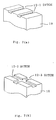
- FIG. 3(a) A first preferred embodiment of connection structure of the present invention is shown in Figs. 3.
- a flat surface 10-1 of block 10 directly contacts a flat surface 2-1 of electro-strictive element 2 without having adhesive therebetween.
- Surface 10-1 is provided with a ditch 12, for example, 0.2 mm deep, and, for example, 1 mm wide.
- An adhesive 13-1 for example a widely employed epoxy resin, is filled in ditch 12 so that block 10 and electro-strictive element 2 is adhered with each other.
- adhesive 13-2 on portions 2-2 of the sides of electro-strictive element 2 in the vicinity of block 10 are provided with adhesive 13-2 so as to enhance the bonding strength between block 10 and electro-strictive element 2.
- Adhesive 13-1 in ditch 12 having a 3 mm2 area allows 6 to 9 kg bonding strength, which is adequate to reliably connect block 10 and electro-strictive element 2.
- adhesive 13-2 on sides of electro-strictive element 2 is supplemental to adhesive 13-1 in ditch 12.
- Fig. 3(b) shows the connection structure between electro-strictive element 2 and base 11, where the same connection structures as that of Fig. 3(a) is employed, accordingly, the same numerals are given for notating the same parts.
- Fig. 4(a) shows a modeled equivalent circuit having no adhesive between the two contacting surfaces.
- Fig. 4(b) shows a modeled equivalent circuit having the adhesive between the two contacting surfaces.
- the base drawn at the right hand side is considered to have an infinite spring constant, that is, the base is considered not to move at all.
- the expansion ⁇ of the electro-strictive element is 100 % output from point P at the left hand side of the element to the block having a spring constant K1.
- K2 indicates a spring constant of the adhesive
- ⁇ L and ⁇ R indicate the displacements at the left and right ends of electro-strictive element, respectively.
- ⁇ ⁇ L + ⁇ R
- K L ⁇ L K2 ⁇ R
- K L K1K2/(K1+ K2) therefore, from equations (1) and (2)
- ⁇ L ⁇ K2/(K L + K2)
- K L ⁇ L K1 ⁇ P (4) therefore, from equations (4),(3) and (6)
- a second preferred embodiment of the connection structure of the present invention is shown in Figs. 5, where a ditch 14 is provided on a surface 2-3 of electro-strictive element 2, while block 10 and base 11 have no ditch thereon.
- An adhesive 13-3 is filled in ditch 14 and supplemental adhesive 13-4 is provided on portions of the sides of electro-strictive element 2 in the vicinity of block 10 and base 11. The same advantageous effect as the first preferred embodiment is accomplished in the second preferred embodiment.
- supplemental adhesive 13-2 or 13-4 is provided along the two facing sides where ditch 12 or 14 is seen, it is apparent that the adhesive may be provided along the other two sides of electro-strictive element 2, or moreover all around the four sides.
- a third preferred embodiment of the connection structure of the present invention is shown in Figs. 6, where no ditch is provided on electro-strictive element, the block and the base, but gaps are provided between end sides of electro-strictive element 2 and banks 10-2, 11-2, each protruding from surfaces 10-4 of block 10 and surface 11-4 of base 11, respectively.
- the gaps are typically 50 to 100 ⁇ m and 1 to 2 mm deep, filled with adhesive material 13-5 so that electro-strictive element 2 is adhered to block 10 and base 11.
- Surfaces 2-4 of electro-strictive element 2 directly contacts the opposite surfaces 10-4 and 11-4, respectively, without adhesive therebetween. Therefore, the direct contact of the surfaces having no ditch allows a good propagation of the mechanical output of the electro-strictive element therethrough, while an adequate bonding force is achieved therebetween.
- the adhesive is provided along the two facing sides of electro-strictive element, it is apparent that the banks and adhesive may be provided along the other two sides of electro-strictive element 2, or moreover all around the four sides.
- Figs. 7 Variations of the ditch are shown in Figs. 7 as a third preferred embodiment of the present invention.
- Fig. 7(a) shows two ditches arranged in parallel.
- Fig. 7(b) shows two ditches arranged crosswise. These structures provides more bonding strength between the electro-strictive element and the block/base. It is apparent that the location and size of the ditch can be arbitrarily determined other than those disclosed in the above preferred embodiment depending on the design requirement.
Abstract

Description
- This invention relates to an electro-strictive actuator, particularly to a structure to connect an electro-strictive element to its mechanical load.
- In a printer head of a wire-dot printer, an electro-strictive element has been recently employed for actuating an impact printing wire in order to satisfy the recent trend aiming at a higher printing speed.
- In a prior art structure shown in Fig. 1 to structurally connect an electro-
strictive element 2 to ametal block 7 to output a mechanical displacement caused from an electro-strictive phenomena, i.e. an expansion, of the electro-strictive element 2 to the impact printing wire,block 7 is adhered to electro-strictive element 2 by an adhesive 13a placed between aflat surface 7a ofblock 7 and aflat surface 2a of electro-strictive element 2, as well as by another adhesive 13b to adhere sides of electro-strictive element 2 toflat surface 7a ofblock 7. The mechanical displacement, i.e. mechanical output, of the electro-strictive element is typically as small as 15 µm. Adhesive 13a between twosurfaces metal block 7 and the electro-strictive element 2, attenuates the propagation of the displacement output from electro-strictive element 2, resulting in a decrease in the mechanical output. If the thickness of the adhesive member is reduced, the adhesion strength is reduced. - It is a general object of the invention to provide a connection structure of an electro-strictive element to a mechanical member to output a mechanical displacement of the electro-strictive element without decrease in the output displacement, while achieving an adequate bonding strength between the electro-strictive element and the mechanical member.
- An electro-strictive actuator of the present invention comprises an electro-strictive element having a first surface through which a mechanical displacement is output; and a mechanical member having a second surface which directly contacts the first flat surface so that the mechanical displacement of the electro-strictive element is output without attenuation to the mechanical member, where the first or the second surface is provided with a ditch filled with a first adhesive for adhering the electro-strictive element to the mechanical member. A portion of the side of the electro-strictive element in the vicinity of the second surface may be additionally adhered to the second surface by a second adhesive.
- The above-mentioned features and advantages of the present invention, together with other objects and advantages, which will become apparent, will be more fully described hereinafter, with references being made to the accompanying drawings which form a part hereof, wherein like numerals refer to like parts throughout.
-
- Fig. 1 schematically illustrates a cross-sectional view of a prior art connection structure of an electro-strictive element to a mechanical block to output the electro-strictive output;
- Fig. 2 schematically illustrates a cross-sectional view of an electro-strictive printing head where the present invention is applicable;
- Figs. 3 schematically illustrate a first preferred embodiment of the connection structure of the present invention;
- Figs. 4 show equivalent circuits of the cases having and not having an adhesive between the two contacting surfaces;
- Figs. 5 schematically illustrate a second preferred embodiment of the connection structure of the present invention;
- Figs. 6 schematically illustrate a third preferred embodiment of the connection structure of the present invention; and
- Figs. 7 schematically illustrate a fourth preferred embodiment of the connection structure of the present invention.
- An electro-strictive printing head where the present invention is applicable to is shown in Fig. 2, where the connection structure is representatively shown with below-described first preferred embodiment. An electro-
strictive element 2 is formed of a stack of a plurality of typically 3.0 mm wide x 2.7 mm wide x 0.1 mm thick sheets of piezoelectric material, typically of a composite PZT, i.e. lead-zirconium-titan oxides ceramic, and film electrodes, as widely employed, and is typically 24 mm thick in the longitudinal length of the electro-strictive element. An application of electrical voltage between the electrodes, i.e. across the piezoelectric sheets, causes a mechanical expansion along the thickness of the sheet, which is the longitudinal axis of electro-strictive element 2 shown in Fig. 2. The piezoelectric sheets and the electrodes are not individually shown in the figures. According to the structure of the present invention a longitudinal end of electro-strictive element 2 is connected to an end of abase 11 made of a metal, typically of an iron alloy having a least thermal expansion coefficient. Again, according to the structure of the present invention another longitudinal end of electro-strictive element 2 is connected to a flat part of ablock 10 made of a metal. An end of amovable member 4 is held to another end ofbase 11 via aspring 5, which acts as a hinge . Another end ofmovable member 4 is fixed with aprinting wire 9. A resiliently thinned portion 15 ofblock 10 is connected tomovable member 4 at a relatively short distance fromspring 5 with respect the distance betweenspring 5 andprinting wire 9. Thus, the mechanical displacement, as small as typically 15 µm, ofblock 10 is amplified to as large as several hundreds, typically 300 µm stroke, ofprinting wire 9. By the stroke ofprinting wire 9, the top end ofprinting wire 9 strikes an ink ribbon onto a sheet held on a platen to print a dot on the sheet. The ribbon, the sheet and the platen are not shown in the figure. - A first preferred embodiment of connection structure of the present invention is shown in Figs. 3. In Fig. 3(a), a flat surface 10-1 of
block 10 directly contacts a flat surface 2-1 of electro-strictive element 2 without having adhesive therebetween. Surface 10-1 is provided with aditch 12, for example, 0.2 mm deep, and, for example, 1 mm wide. An adhesive 13-1, for example a widely employed epoxy resin, is filled inditch 12 so thatblock 10 and electro-strictive element 2 is adhered with each other. Additionally, on portions 2-2 of the sides of electro-strictive element 2 in the vicinity ofblock 10 are provided with adhesive 13-2 so as to enhance the bonding strength betweenblock 10 and electro-strictive element 2. Adhesive 13-1 inditch 12 having a 3 mm² area allows 6 to 9 kg bonding strength, which is adequate to reliably connectblock 10 and electro-strictive element 2. Thus, adhesive 13-2 on sides of electro-strictive element 2 is supplemental to adhesive 13-1 inditch 12. - Fig. 3(b) shows the connection structure between electro-
strictive element 2 andbase 11, where the same connection structures as that of Fig. 3(a) is employed, accordingly, the same numerals are given for notating the same parts. - Due to the direct contact between electro-
strictive element 2 andblock 10/base 11, the displacement output from electro-strictive element 2 is propagated to block 10/base 11 without attenuation. - Effect of the deletion of the adhesive between the two flat surfaces of electro-
strictive element 2 andblock 10/base 11 is evaluated as follows. Fig. 4(a) shows a modeled equivalent circuit having no adhesive between the two contacting surfaces. Fig. 4(b) shows a modeled equivalent circuit having the adhesive between the two contacting surfaces. In Fig. 4(a), the base drawn at the right hand side is considered to have an infinite spring constant, that is, the base is considered not to move at all. Accordingly, the expansion δ of the electro-strictive element is 100 % output from point P at the left hand side of the element to the block having a spring constant K₁. In Fig. 4(b), K₂ indicates a spring constant of the adhesive, and δL and δR indicate the displacements at the left and right ends of electro-strictive element, respectively. Then,


where:
therefore, from equations (1) and (2)

and,

therefore, from equations (4),(3) and (6)

practical values are:
K₁ = 150 kgf /mm
K₂ = 8.1 x 10³ kgf /mm
for the case where the adhesive is 0.1 mm thick, and has Young module:300 kgf /mm² and adhesion area 2.7 mm x 3 mm;
therefore, by substituting the practical values to equation (5),

Thus, approximately 4 % decrease in the output displacement is recovered by the deletion of the adhesive between the two contacting faces, at each end of electro-strictive element. - A second preferred embodiment of the connection structure of the present invention is shown in Figs. 5, where a
ditch 14 is provided on a surface 2-3 of electro-strictive element 2, whileblock 10 andbase 11 have no ditch thereon. An adhesive 13-3 is filled inditch 14 and supplemental adhesive 13-4 is provided on portions of the sides of electro-strictive element 2 in the vicinity ofblock 10 andbase 11. The same advantageous effect as the first preferred embodiment is accomplished in the second preferred embodiment. - Though in the above preferred embodiments the supplemental adhesive 13-2 or 13-4 is provided along the two facing sides where
ditch strictive element 2, or moreover all around the four sides. - A third preferred embodiment of the connection structure of the present invention is shown in Figs. 6, where no ditch is provided on electro-strictive element, the block and the base, but gaps are provided between end sides of electro-
strictive element 2 and banks 10-2, 11-2, each protruding from surfaces 10-4 ofblock 10 and surface 11-4 ofbase 11, respectively. The gaps are typically 50 to 100 µm and 1 to 2 mm deep, filled with adhesive material 13-5 so that electro-strictive element 2 is adhered to block 10 andbase 11. Surfaces 2-4 of electro-strictive element 2 directly contacts the opposite surfaces 10-4 and 11-4, respectively, without adhesive therebetween. Therefore, the direct contact of the surfaces having no ditch allows a good propagation of the mechanical output of the electro-strictive element therethrough, while an adequate bonding force is achieved therebetween. - Though in the third preferred embodiment the adhesive is provided along the two facing sides of electro-strictive element, it is apparent that the banks and adhesive may be provided along the other two sides of electro-
strictive element 2, or moreover all around the four sides. - Variations of the ditch are shown in Figs. 7 as a third preferred embodiment of the present invention. Fig. 7(a) shows two ditches arranged in parallel. Fig. 7(b) shows two ditches arranged crosswise. These structures provides more bonding strength between the electro-strictive element and the block/base. It is apparent that the location and size of the ditch can be arbitrarily determined other than those disclosed in the above preferred embodiment depending on the design requirement.
- The many features and advantages of the invention are apparent from the detailed specification and thus, it is intended by the appended claims to cover all such features and advantages of the methods which fall within the true spirit and scope of the invention. Further, since numerous modifications and changes will readily occur to those skilled in the art, it is not detailed to limit the invention and accordingly, all suitable modifications are equivalents may be resorted to, falling within the scope of the invention.
Claims (11)
- An electro-strictive actuator comprising:
an electro-strictive element (2) having a first surface (2-1) through which a mechanical displacement is output;
a mechanical member (10, 11) having a second surface (10-1, 11-1) for mechanically connecting said electro-strictive element to a load of the actuator, said second surface directly contacting said first surface; and
a first adhesive member (13-1) being provided for adhering said electro-strictive element to said mechanical member. - An electro-strictive actuator as recited in claim 1, comprising:
an electro-strictive element (2) having a first surface (2-1) through which a mechanical displacement is output;
a mechanical member (10, 11) having a second surface (10-1, 11-1) for mechanically connecting said electro-strictive element to a load of the actuator, said second surface directly contacting said first surface, said second surface having a ditch (12); and
a first adhesive member (13-1) filled in said ditch, for adhering said electro-strictive element to said mechanical member. - An electro-strictive actuator as recited in claim 1 or 2, wherein said load of the actuator is a printing wire (9) provided in a printing head.
- An electro-strictive actuator as recited in claim 1, 2 or 3, further comprising:
a second adhesive member (13-2) for adhering said second surface (10-1, 11-1) to a side (2-2) of said electro-strictive element, said side being substantially orthogonal to said first surface. - An electro-strictive actuator as recited in claim 4, wherein plural second adhesive members (13-2) are provided for adhering a plurality of said sides (2-2).
- An electro-strictive actuator as recited in any preceding claim, comprising:
an electro-strictive element (2) having a first surface (2-3) through which a mechanical displacement is output, said first surface having a ditch (14);
a mechanical member (10, 11) having a second surface, for mechanically connecting said electro-strictive element to a load of the actuator, said second surface directly contacting said first surface; and
an adhesive member (13-3) filled in said ditch (14), for adhering said electro-strictive element to said mechanical member. - An electro-strictive actuator as recited in claim 1, 2 or 6, wherein said load of the actuator is a printer head to actuate a printing wire (9).
- An electro-strictive actuator as recited in claim 1, 2, 6 or 7, further comprising:
a second adhesive member (13-4) for adhering said second surface to a side of said electro-strictive element, said side being substantially orthogonal to said first surface. - An electro-strictive actuator as recited in claim 8, wherein plural second adhesive members (13-4) are provided for adhering a plurality of said sides.
- An electro-strictive actuator as recited in any preceding claim, comprising:
an electro-strictive element (2), having a first surface (2-4) through which a mechanical displacement is output and having a side (2-2) substantially orthogonal to said first surface;
a mechanical member (10, 11) having a second surface (10-4, 11-4), for mechanically connecting said electro-strictive element to a load of the actuator, said second surface directly contacting said first surface;
a plurality of banks (10-2, 11-2) protruding from said second surface, a gap being provided between said bank and said side; and
an adhesive member (13-5) filled in said gap, for adhering said side to said bank. - An electro-strictive actuator as recited in claim 10, wherein said load of the actuator is a printer head to actuate a printing wire (9).
Applications Claiming Priority (2)
| Application Number | Priority Date | Filing Date | Title |
|---|---|---|---|
| JP1990130424U JPH0487253U (en) | 1990-11-30 | 1990-11-30 | |
| JP130424/90U | 1990-11-30 |
Publications (2)
| Publication Number | Publication Date |
|---|---|
| EP0488232A1 true EP0488232A1 (en) | 1992-06-03 |
| EP0488232B1 EP0488232B1 (en) | 1996-03-27 |
Family
ID=15033916
Family Applications (1)
| Application Number | Title | Priority Date | Filing Date |
|---|---|---|---|
| EP91120297A Expired - Lifetime EP0488232B1 (en) | 1990-11-30 | 1991-11-27 | An electrostrictive actuator |
Country Status (4)
| Country | Link |
|---|---|
| US (1) | US5331241A (en) |
| EP (1) | EP0488232B1 (en) |
| JP (1) | JPH0487253U (en) |
| DE (1) | DE69118329T2 (en) |
Cited By (3)
| Publication number | Priority date | Publication date | Assignee | Title |
|---|---|---|---|---|
| DE19833782A1 (en) * | 1998-07-27 | 2000-02-03 | Abb Instrumentation Ltd | Drive arrangement for a write head |
| DE19857922A1 (en) * | 1998-12-15 | 2000-07-06 | Siemens Ag | Actuator for deflecting an actuator and fuel injection valve with such an actuator |
| DE10139686B4 (en) * | 2000-10-05 | 2007-02-01 | Eads Deutschland Gmbh | Piezoelectric strain actuator |
Families Citing this family (6)
| Publication number | Priority date | Publication date | Assignee | Title |
|---|---|---|---|---|
| US5440193A (en) * | 1990-02-27 | 1995-08-08 | University Of Maryland | Method and apparatus for structural, actuation and sensing in a desired direction |
| JPH0559951U (en) * | 1992-01-09 | 1993-08-06 | 株式会社村田製作所 | Piezoelectric parts |
| US6211602B1 (en) * | 1997-06-24 | 2001-04-03 | Minolta Co., Ltd. | Actuator using electromechanical transducer capable of being used in high temperature and high humidity environment and apparatus having the same |
| US7480432B2 (en) * | 2006-02-28 | 2009-01-20 | Corning Incorporated | Glass-based micropositioning systems and methods |
| JP7254285B2 (en) * | 2019-04-23 | 2023-04-10 | 株式会社サタケ | Piezoelectric valve and manufacturing method of the piezoelectric valve |
| JP7193804B2 (en) * | 2019-06-05 | 2022-12-21 | 株式会社サタケ | Piezoelectric Actuator, Piezoelectric Valve, and Piezoelectric Actuator Manufacturing Method |
Citations (2)
| Publication number | Priority date | Publication date | Assignee | Title |
|---|---|---|---|---|
| EP0144655A1 (en) * | 1983-10-19 | 1985-06-19 | Nec Corporation | Electrostriction transducer comprising electrostriction layers of axially varied thicknesses |
| US4937489A (en) * | 1987-09-16 | 1990-06-26 | Ngk Spark Plug Co., Ltd. | Electrostrictive actuators |
Family Cites Families (18)
| Publication number | Priority date | Publication date | Assignee | Title |
|---|---|---|---|---|
| US3140859A (en) * | 1961-01-17 | 1964-07-14 | Internat Ultrasonics Inc | Electroacoustic sandwich transducers |
| US3427480A (en) * | 1966-06-16 | 1969-02-11 | Sonoptics Corp | Piezoelectric cleaning device |
| US3518766A (en) * | 1969-01-30 | 1970-07-07 | Emanuel Burt | Piezoelectric cleaning device with removable workpiece |
| JPS5112497B1 (en) * | 1971-04-21 | 1976-04-20 | ||
| US4229812A (en) * | 1971-11-24 | 1980-10-21 | The United States Of America As Represented By The Secretary Of The Navy | Apparatus for securing a ferroelectric stack to a weighted projection surface |
| US3891869A (en) * | 1973-09-04 | 1975-06-24 | Scarpa Lab Inc | Piezoelectrically driven ultrasonic generator |
| PL101987B1 (en) * | 1976-06-16 | 1979-02-28 | Politechnika Wroclawska | ELECTRO-ACOUSTIC LAMINAR TRANSDUCER AND METHOD FOR MANUFACTURING DRY TRANSDUCERS |
| US4195243A (en) * | 1978-11-06 | 1980-03-25 | Sperry Corporation | Piezoelectric wafer mover |
| US4217781A (en) * | 1979-04-18 | 1980-08-19 | Micro Pure Systems, Inc. | Ultrasonic particulate sensing |
| US4435666A (en) * | 1981-05-26 | 1984-03-06 | Nippon Electric Co., Ltd. | Lever actuator comprising a longitudinal-effect electroexpansive transducer and designed to prevent actuation from degrading the actuator |
| JPS59211A (en) * | 1982-06-25 | 1984-01-05 | Kinseki Kk | Holding structure of piezoelectric vibrator |
| US4530138A (en) * | 1982-09-30 | 1985-07-23 | Westinghouse Electric Corp. | Method of making a transducer assembly |
| US4764021A (en) * | 1983-02-22 | 1988-08-16 | Corning Glass Works | Apparatus for ultrasonic agitation of liquids |
| JPS62108607A (en) * | 1985-11-06 | 1987-05-19 | Murata Mfg Co Ltd | Piezoelectric parts |
| JPH02106983A (en) * | 1988-10-17 | 1990-04-19 | Murata Mfg Co Ltd | Piezoelectric functional part |
| JPH0318279A (en) * | 1989-06-14 | 1991-01-25 | Nissan Motor Co Ltd | Ultrasonic motor |
| JPH07108102B2 (en) * | 1990-05-01 | 1995-11-15 | 日本碍子株式会社 | Method for manufacturing piezoelectric / electrostrictive film type actuator |
| US5210455A (en) * | 1990-07-26 | 1993-05-11 | Ngk Insulators, Ltd. | Piezoelectric/electrostrictive actuator having ceramic substrate having recess defining thin-walled portion |
-
1990
- 1990-11-30 JP JP1990130424U patent/JPH0487253U/ja active Pending
-
1991
- 1991-11-27 EP EP91120297A patent/EP0488232B1/en not_active Expired - Lifetime
- 1991-11-27 DE DE69118329T patent/DE69118329T2/en not_active Expired - Fee Related
-
1993
- 1993-08-27 US US08/112,228 patent/US5331241A/en not_active Expired - Lifetime
Patent Citations (2)
| Publication number | Priority date | Publication date | Assignee | Title |
|---|---|---|---|---|
| EP0144655A1 (en) * | 1983-10-19 | 1985-06-19 | Nec Corporation | Electrostriction transducer comprising electrostriction layers of axially varied thicknesses |
| US4937489A (en) * | 1987-09-16 | 1990-06-26 | Ngk Spark Plug Co., Ltd. | Electrostrictive actuators |
Cited By (5)
| Publication number | Priority date | Publication date | Assignee | Title |
|---|---|---|---|---|
| DE19833782A1 (en) * | 1998-07-27 | 2000-02-03 | Abb Instrumentation Ltd | Drive arrangement for a write head |
| US6331037B1 (en) | 1998-07-27 | 2001-12-18 | Abb Instrumentation Limited | Drive arrangement for a writing head |
| DE19857922A1 (en) * | 1998-12-15 | 2000-07-06 | Siemens Ag | Actuator for deflecting an actuator and fuel injection valve with such an actuator |
| DE10139686B4 (en) * | 2000-10-05 | 2007-02-01 | Eads Deutschland Gmbh | Piezoelectric strain actuator |
| US7453185B2 (en) | 2000-10-05 | 2008-11-18 | Eads Deutschland Gmbh | Piezoelectric extension actuator |
Also Published As
| Publication number | Publication date |
|---|---|
| US5331241A (en) | 1994-07-19 |
| DE69118329D1 (en) | 1996-05-02 |
| DE69118329T2 (en) | 1996-08-08 |
| JPH0487253U (en) | 1992-07-29 |
| EP0488232B1 (en) | 1996-03-27 |
Similar Documents
| Publication | Publication Date | Title |
|---|---|---|
| US4435666A (en) | Lever actuator comprising a longitudinal-effect electroexpansive transducer and designed to prevent actuation from degrading the actuator | |
| CA1239965A (en) | Electrostriction transducer comprising electrostriction layers of axially varied thicknesses | |
| EP0616222B1 (en) | Acceleration sensor | |
| US5276657A (en) | Metal-electroactive ceramic composite actuators | |
| US6060811A (en) | Advanced layered composite polylaminate electroactive actuator and sensor | |
| US5592042A (en) | Piezoelectric/electrostrictive actuator | |
| US5831371A (en) | Snap-action ferroelectric transducer | |
| EP0262637A2 (en) | Piezoelectric actuator | |
| EP0488232B1 (en) | An electrostrictive actuator | |
| EP0901172B1 (en) | Piezoelectric actuator | |
| JP4460742B2 (en) | Piezoelectric / electrostrictive device and manufacturing method thereof | |
| US5400488A (en) | Method of manufacturing a piezoelectric vibrator capable of reliably preventing dielectric breakdown | |
| EP0536637B1 (en) | Piezo-electric device type actuator | |
| EP0333595B1 (en) | Printing head of wire-dot impact printer | |
| KR0121752B1 (en) | Device for magnifying displacement of piezoelectric element and method of producing the same | |
| KR20020023236A (en) | Piezoelectric actuator | |
| EP0587192B1 (en) | Electro-distortion device | |
| EP0896226A1 (en) | Acceleration sensor | |
| JPH0132750Y2 (en) | ||
| JPH0132758Y2 (en) | ||
| JPH0132749Y2 (en) | ||
| JPH0541881Y2 (en) | ||
| JPH0234040Y2 (en) | ||
| JP2508249B2 (en) | Piezoelectric actuator | |
| Ota et al. | Piezoelectric latching relay |
Legal Events
| Date | Code | Title | Description |
|---|---|---|---|
| PUAI | Public reference made under article 153(3) epc to a published international application that has entered the european phase |
Free format text: ORIGINAL CODE: 0009012 |
|
| AK | Designated contracting states |
Kind code of ref document: A1 Designated state(s): DE FR GB |
|
| 17P | Request for examination filed |
Effective date: 19921105 |
|
| 17Q | First examination report despatched |
Effective date: 19940811 |
|
| GRAA | (expected) grant |
Free format text: ORIGINAL CODE: 0009210 |
|
| AK | Designated contracting states |
Kind code of ref document: B1 Designated state(s): DE FR GB |
|
| REF | Corresponds to: |
Ref document number: 69118329 Country of ref document: DE Date of ref document: 19960502 |
|
| ET | Fr: translation filed | ||
| PLBE | No opposition filed within time limit |
Free format text: ORIGINAL CODE: 0009261 |
|
| STAA | Information on the status of an ep patent application or granted ep patent |
Free format text: STATUS: NO OPPOSITION FILED WITHIN TIME LIMIT |
|
| 26N | No opposition filed | ||
| REG | Reference to a national code |
Ref country code: GB Ref legal event code: IF02 |
|
| PGFP | Annual fee paid to national office [announced via postgrant information from national office to epo] |
Ref country code: FR Payment date: 20041109 Year of fee payment: 14 |
|
| PGFP | Annual fee paid to national office [announced via postgrant information from national office to epo] |
Ref country code: GB Payment date: 20041124 Year of fee payment: 14 |
|
| PGFP | Annual fee paid to national office [announced via postgrant information from national office to epo] |
Ref country code: DE Payment date: 20041125 Year of fee payment: 14 |
|
| PG25 | Lapsed in a contracting state [announced via postgrant information from national office to epo] |
Ref country code: GB Free format text: LAPSE BECAUSE OF NON-PAYMENT OF DUE FEES Effective date: 20051127 |
|
| PG25 | Lapsed in a contracting state [announced via postgrant information from national office to epo] |
Ref country code: DE Free format text: LAPSE BECAUSE OF NON-PAYMENT OF DUE FEES Effective date: 20060601 |
|
| GBPC | Gb: european patent ceased through non-payment of renewal fee |
Effective date: 20051127 |
|
| PG25 | Lapsed in a contracting state [announced via postgrant information from national office to epo] |
Ref country code: FR Free format text: LAPSE BECAUSE OF NON-PAYMENT OF DUE FEES Effective date: 20060731 |
|
| REG | Reference to a national code |
Ref country code: FR Ref legal event code: ST Effective date: 20060731 |