EP0487869A1 - Dispositif semi-conducteur de puissance, à extinction - Google Patents
Dispositif semi-conducteur de puissance, à extinction Download PDFInfo
- Publication number
- EP0487869A1 EP0487869A1 EP91117112A EP91117112A EP0487869A1 EP 0487869 A1 EP0487869 A1 EP 0487869A1 EP 91117112 A EP91117112 A EP 91117112A EP 91117112 A EP91117112 A EP 91117112A EP 0487869 A1 EP0487869 A1 EP 0487869A1
- Authority
- EP
- European Patent Office
- Prior art keywords
- layer
- mosfet
- gate electrode
- emitter layer
- cathode
- Prior art date
- Legal status (The legal status is an assumption and is not a legal conclusion. Google has not performed a legal analysis and makes no representation as to the accuracy of the status listed.)
- Granted
Links
- 239000004065 semiconductor Substances 0.000 title claims abstract description 20
- 230000015556 catabolic process Effects 0.000 claims abstract description 11
- 239000000758 substrate Substances 0.000 claims description 14
- 230000003071 parasitic effect Effects 0.000 claims description 4
- 230000000295 complement effect Effects 0.000 claims description 2
- 238000002347 injection Methods 0.000 description 5
- 239000007924 injection Substances 0.000 description 5
- 238000005516 engineering process Methods 0.000 description 4
- 238000009413 insulation Methods 0.000 description 3
- 238000000034 method Methods 0.000 description 3
- 230000000903 blocking effect Effects 0.000 description 2
- 230000001419 dependent effect Effects 0.000 description 2
- 238000010586 diagram Methods 0.000 description 2
- 239000000463 material Substances 0.000 description 2
- 241001136792 Alle Species 0.000 description 1
- 241001481828 Glyptocephalus cynoglossus Species 0.000 description 1
- 239000002800 charge carrier Substances 0.000 description 1
- 230000002950 deficient Effects 0.000 description 1
- 238000009826 distribution Methods 0.000 description 1
- 230000000694 effects Effects 0.000 description 1
- 238000002955 isolation Methods 0.000 description 1
Images

Classifications
-
- H—ELECTRICITY
- H01—ELECTRIC ELEMENTS
- H01L—SEMICONDUCTOR DEVICES NOT COVERED BY CLASS H10
- H01L29/00—Semiconductor devices specially adapted for rectifying, amplifying, oscillating or switching and having potential barriers; Capacitors or resistors having potential barriers, e.g. a PN-junction depletion layer or carrier concentration layer; Details of semiconductor bodies or of electrodes thereof ; Multistep manufacturing processes therefor
- H01L29/66—Types of semiconductor device ; Multistep manufacturing processes therefor
- H01L29/68—Types of semiconductor device ; Multistep manufacturing processes therefor controllable by only the electric current supplied, or only the electric potential applied, to an electrode which does not carry the current to be rectified, amplified or switched
- H01L29/70—Bipolar devices
- H01L29/74—Thyristor-type devices, e.g. having four-zone regenerative action
- H01L29/749—Thyristor-type devices, e.g. having four-zone regenerative action with turn-on by field effect
-
- H—ELECTRICITY
- H01—ELECTRIC ELEMENTS
- H01L—SEMICONDUCTOR DEVICES NOT COVERED BY CLASS H10
- H01L29/00—Semiconductor devices specially adapted for rectifying, amplifying, oscillating or switching and having potential barriers; Capacitors or resistors having potential barriers, e.g. a PN-junction depletion layer or carrier concentration layer; Details of semiconductor bodies or of electrodes thereof ; Multistep manufacturing processes therefor
- H01L29/66—Types of semiconductor device ; Multistep manufacturing processes therefor
- H01L29/68—Types of semiconductor device ; Multistep manufacturing processes therefor controllable by only the electric current supplied, or only the electric potential applied, to an electrode which does not carry the current to be rectified, amplified or switched
- H01L29/70—Bipolar devices
- H01L29/74—Thyristor-type devices, e.g. having four-zone regenerative action
- H01L29/744—Gate-turn-off devices
- H01L29/745—Gate-turn-off devices with turn-off by field effect
- H01L29/7455—Gate-turn-off devices with turn-off by field effect produced by an insulated gate structure
Definitions
- GTO Gate Turn Off
- the GTO divides the entire chip area into a large number of unit cells connected in parallel. These components can be switched on and off via the gate contact; Because of the high gate currents when switching off, however, an enormous amount of circuitry for the gate control must be accepted.
- MOS-controlled components For some years now, the development of MOS-controlled components has been increasingly promoted in power electronics.
- the advantage of these MOS-controlled components lies mainly in the high input impedance at the control electrode. It enables the component to be controlled with a comparatively very low level of performance.
- bipolar structures eg thyristors
- the simple and, in particular, low-power control should, as far as possible used in power MOSFETs.
- MOS-controlled thyristor or MCT M OS C ontrolled T hyristor
- GTO GTO consists of a plurality of adjacent, parallel-connected unit cells
- the shutdown is achieved a short-circuit of the emitter with the p-type base by means of switchable emitter shorts.
- MOSFETs integrated with the emitter serve as switches, which can naturally be designed as n- or p-channel MOSFETs.
- the essence of the invention is to provide a five-layer structure between the anode and the cathode instead of the usual bipolar pnpn thyristor structure consisting of four layers, with a p auf-doped layer directly connected to the cathode as the fifth layer on the cathode side Contact area is arranged.
- the contact area is bridged by a MOSFET.
- this additional layer lies between the cathode and the p-n-p-n thyristor structure and effectively prevents the electron injection leading to filamentation.
- the means comprise a second MOSFET which is formed from the contact region, the n-emitter layer, the p-base layer and a second gate electrode arranged above the n-emitter layer.
- the bipolar transistor which is automatically turned on when switched off, takes over the function of the second MOSFET.
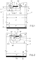
- Fig. 1 the unit cell of a preferred embodiment of the component according to the invention is shown in cross section.
- the component is generally therefore hereinafter be referred to a five layers comprehensive, an insulated gate-controlled bipolar switch and is briefly as IG-FiBS (Insulated Gate Bipolar controlled F ive layer S witch).
- IG-FiBS Insulated Gate Bipolar controlled F ive layer S witch
- the IG-FiBS consists of a semiconductor substrate 1 with an upper and a lower main surface.
- the lower main surface is provided with an anode contact 10 which is connected to the anode A.
- the upper main surface carries a cathode contact 2 within each unit cell, which in turn is connected to the cathode K.
- a layer sequence of five layers doped with alternating polarity is arranged within the semiconductor substrate 1, which layers successively have a p+-doped p-emitter layer 9, an n ⁇ -doped n-base layer 8, a p+- doped p-base layer 7, an n+-doped n-emitter layer 6 and a piertes-doped contact region 5.
- the p-emitter layer 9 is contacted by the anode contact 10, the contact region 5 on the other side of the semiconductor substrate by the cathode contact 2.
- a first MOSFET M1 is integrated on the one side and a second MOSFET M2 on the other side in the semiconductor substrate 1.
- the first MOSFET M1 is composed of the n-emitter layer 6, the contact region 5, an n+-doped source region 4 embedded in the contact region 5 and connected to the cathode contact 2, and a first gate electrode G1 arranged above the contact region 5 (gate insulation 3) educated. It is an n-channel MOSFET, the channel region of which is part of the contact region 5 which occurs between the n-emitter layer 6 and the source region 4.
- the second MOSFET M2 is formed from the p-base layer 7, the n-emitter layer 6, the contact region 5 and a second gate electrode G2 arranged insulated above the n-emitter layer 6 (gate insulation 3). It is a p-channel MOSFET, the channel region of which is part of the n-emitter layer 6 that occurs between the trough-shaped contact region 5 and the p-base layer 7.
- the parameters of the unit cell of the embodiment from FIG. 1 can be selected, for example, as follows: the unit cell has a width b of approximately 20 ⁇ m.
- the thickness d of the semiconductor substrate 1 is approximately 420 ⁇ m.
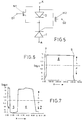
- the course of the doping concentration c (in cm ⁇ 3), which results along the section lines AA and BB shown in FIG. 1, is dependent on logarithmic plotting in FIG. 7 (section AA) and in FIG. 6 (section BB) of the distance x from the substrate surface (see Fig. 1).
- the doping concentration for n-doped material is removed from the dashed zero line upwards, the corresponding doping concentration for p-doped material downwards. It can be seen from FIGS.
- n base layer 8 is, for example, a doping concentration of about 5x1013 cm ⁇ 3, while the n-emitter layer 6 has a doping concentration of about 1018 cm ⁇ 3 and the p-doped contact region 5 has a doping concentration of about 1019 cm ⁇ 3.
- the component according to FIG. 1 can be understood in an equivalent circuit diagram (FIG. 5) as an anti-parallel series circuit comprising a diode D and a thyristor T, the diode D being able to be bridged by the first MOSFET M1, while the second MOSFET M2 is between the cathode K and the gate of the thyristor T is connected.
- FIG. 5 an equivalent circuit diagram
- the function of the component according to FIG. 1 is as follows: in the ON state, the first gate electrode G1 has a positive gate voltage relative to the cathode K.
- the first MOSFET M1 is thus switched on and short-circuits the cathode contact 2 with the n-emitter layer 6, which acts as an emitter for the rest of the component.
- the short circuit reduces the active structure of the component to a pnpn sequence of four layers (p-emitter layer 9, n-base layer 8, p-base layer 7 and n-emitter layer 6), which - apart from the channel resistance of the first MOSFET that can be made very small - behaves like a conventional thyristor.
- the second MOSFET M2 is blocked in this phase.
- the gate voltage at the first gate electrode G1 is reduced, so that the first MOSFET M1 changes to the blocked state.
- the IG-FiBS is converted from the four-layer to a five-layer (pnpnp) structure and switches off.
- the additional p-doped contact region 5 basically completely stops the electron injection from the cathode side.
- the second MOSFET M2 is switched on, which then takes over the full cut-off current. This is necessary in order to prevent an avalanche breakdown at the PN junction between the contact region 5 and the n-emitter layer 6.
- This PN junction has a rather low breakdown voltage (on the order of 10-20 V), which is far below the blocking capability of the entire component. An avalanche breakthrough at this PN junction would then prevent the component from being switched off or at least considerably slow down the switch-off process.
- the cathode is formed by the p-doped contact region 5 when it is switched off. For this reason, electron injection is not possible at all. Rather, an increase in the voltage or the current in the IG-FiBS structure during the shutdown results in a faster breakdown of the stored charge carriers, ie in a faster turn-off.
- the IG-FiBS is therefore self-stabilizing.
- the structure shown in FIG. 1 comprises the two MOSFETs M1 and M2, both of which - as explained above - are necessary for the switch-off process.
- a third MOSFET M3 (FIG. 2) can then be provided for switching on the component.
- This third MOSFET M3 is formed by the n-base layer 8, the p-base layer 7, the n-emitter layer 6 and a further gate electrode arranged insulated above the p-base layer 7. As shown in FIG. 2, this further gate electrode can be combined with the first gate electrode G1 to form a common third gate electrode G3. In this way, the first and the third MOSFET M1 and M3 are integrated next to one another and electrically connected in series.
- the three MOSFETs M1, M2 and M3 are arranged next to one another on the same side and connected in series.
- the gate electrodes of the three MOSFETs are then combined to form a common fourth gate electrode G4.
- MOSFETs M1, M2 and M3 are also possible within the scope of the invention. It is particularly conceivable to arrange the first MOSFET M1 on one side of the cathode contact and to combine the MOSFETs M2 and M3 on the other side. It is also conceivable to provide other known means for switching on the component instead of the third MOSFET M3.
- FIG. 4 represents a variant of the embodiment shown in FIG. 1.
- a bipolar, parasitic pnp layer formed from the contact region 5, n-emitter layer 6 and p-base layer 7 is used here.
- Transistor used by a deliberate avalanche breakthrough is ignited and then the cut-off current (indicated in Fig. 4 by the two arrows) takes over.
- the n-emitter layer 6 runs out towards the upper main surface of the semiconductor substrate 1 in a narrow, less doped (n + instead of n ++) base region 11, which is adjacent to a more heavily doped (p ++ instead of p +) sub-region 12 of the p-base layer 7.
- the bipolar transistor has a high current gain ⁇ and can easily be switched on by a breakdown in this area.
- the remaining parts of the structure perform the same tasks as in the embodiment according to FIG. 1.
- a further MOSFET can therefore also be provided for switching on and combined with the first MOSFET M1, similar to that in FIG. 2.
- the invention results in an easily controllable, safely switchable high-performance component, in which filamentation of the current is avoided when switching off, and which is comparatively simple to produce.
Landscapes
- Engineering & Computer Science (AREA)
- Microelectronics & Electronic Packaging (AREA)
- Power Engineering (AREA)
- Physics & Mathematics (AREA)
- Ceramic Engineering (AREA)
- Condensed Matter Physics & Semiconductors (AREA)
- General Physics & Mathematics (AREA)
- Computer Hardware Design (AREA)
- Thyristors (AREA)
Applications Claiming Priority (2)
| Application Number | Priority Date | Filing Date | Title |
|---|---|---|---|
| CH378390 | 1990-11-29 | ||
| CH3783/90 | 1990-11-29 |
Publications (2)
| Publication Number | Publication Date |
|---|---|
| EP0487869A1 true EP0487869A1 (fr) | 1992-06-03 |
| EP0487869B1 EP0487869B1 (fr) | 1997-02-12 |
Family
ID=4263387
Family Applications (1)
| Application Number | Title | Priority Date | Filing Date |
|---|---|---|---|
| EP91117112A Expired - Lifetime EP0487869B1 (fr) | 1990-11-29 | 1991-10-08 | Dispositif semi-conducteur de puissance, à extinction |
Country Status (4)
| Country | Link |
|---|---|
| US (1) | US5625203A (fr) |
| EP (1) | EP0487869B1 (fr) |
| JP (1) | JPH04268766A (fr) |
| DE (1) | DE59108541D1 (fr) |
Cited By (4)
| Publication number | Priority date | Publication date | Assignee | Title |
|---|---|---|---|---|
| EP0454201A2 (fr) * | 1990-04-09 | 1991-10-30 | Philips Electronics Uk Limited | Dispositif semi-conducteur comprenant un thyristor |
| EP0520355A1 (fr) * | 1991-06-28 | 1992-12-30 | Asea Brown Boveri Ag | Composant semi-conducteur de puissance à commande d'extinction et procédé de sa fabrication |
| GB2289371A (en) * | 1994-05-05 | 1995-11-15 | Fuji Electric Co Ltd | A semiconductor device and control method |
| EP0697736A2 (fr) * | 1994-08-08 | 1996-02-21 | ABB Management AG | Dispositif semi-conducteur de puissance contrÔlé MOS à hautes tensions |
Families Citing this family (6)
| Publication number | Priority date | Publication date | Assignee | Title |
|---|---|---|---|---|
| DE4402877C2 (de) * | 1994-02-01 | 1995-12-14 | Daimler Benz Ag | Durch MOS-Gate schaltbares Leistungshalbleiterbauelement |
| EP0718893A3 (fr) * | 1994-11-25 | 1999-07-14 | Fuji Electric Co., Ltd. | Thyristor à contrÔle MOS ayant deux grilles et procédé de fabrication |
| US6107649A (en) * | 1998-06-10 | 2000-08-22 | Rutgers, The State University | Field-controlled high-power semiconductor devices |
| US6959870B2 (en) * | 1999-06-07 | 2005-11-01 | Metrologic Instruments, Inc. | Planar LED-based illumination array (PLIA) chips |
| US20020179968A1 (en) * | 2001-05-30 | 2002-12-05 | Frank Pfirsch | Power semiconductor component, compensation component, power transistor, and method for producing power semiconductor components |
| US20140157223A1 (en) * | 2008-01-17 | 2014-06-05 | Klas Olof Lilja | Circuit and layout design methods and logic cells for soft error hard integrated circuits |
Citations (2)
| Publication number | Priority date | Publication date | Assignee | Title |
|---|---|---|---|---|
| EP0106059A1 (fr) * | 1982-08-18 | 1984-04-25 | Siemens Aktiengesellschaft | Commutateur semi-conducteur muni d'un thyristor à blocage par la gâchette |
| EP0454201A2 (fr) * | 1990-04-09 | 1991-10-30 | Philips Electronics Uk Limited | Dispositif semi-conducteur comprenant un thyristor |
Family Cites Families (1)
| Publication number | Priority date | Publication date | Assignee | Title |
|---|---|---|---|---|
| EP0219995B1 (fr) * | 1985-09-30 | 1994-03-02 | Kabushiki Kaisha Toshiba | Thyristor à commande d'extinction comportant des transistors d'allumage/extinction indépendants |
-
1991
- 1991-10-08 EP EP91117112A patent/EP0487869B1/fr not_active Expired - Lifetime
- 1991-10-08 DE DE59108541T patent/DE59108541D1/de not_active Expired - Fee Related
- 1991-11-25 JP JP3308127A patent/JPH04268766A/ja active Pending
-
1995
- 1995-05-26 US US08/451,994 patent/US5625203A/en not_active Expired - Fee Related
Patent Citations (2)
| Publication number | Priority date | Publication date | Assignee | Title |
|---|---|---|---|---|
| EP0106059A1 (fr) * | 1982-08-18 | 1984-04-25 | Siemens Aktiengesellschaft | Commutateur semi-conducteur muni d'un thyristor à blocage par la gâchette |
| EP0454201A2 (fr) * | 1990-04-09 | 1991-10-30 | Philips Electronics Uk Limited | Dispositif semi-conducteur comprenant un thyristor |
Non-Patent Citations (1)
| Title |
|---|
| IEEE TRANSACTIONS ON ELECTRON DEVICES. Bd. ED-33, Nr. 10, Oktober 1986, NEW YORK US Seiten 1609 - 1618; V. A. K. TEMPLE: 'MOS-controlled thyristors - A new class of power devices' * |
Cited By (8)
| Publication number | Priority date | Publication date | Assignee | Title |
|---|---|---|---|---|
| EP0454201A2 (fr) * | 1990-04-09 | 1991-10-30 | Philips Electronics Uk Limited | Dispositif semi-conducteur comprenant un thyristor |
| EP0454201B1 (fr) * | 1990-04-09 | 1996-10-30 | Philips Electronics Uk Limited | Dispositif semi-conducteur comprenant un thyristor |
| EP0520355A1 (fr) * | 1991-06-28 | 1992-12-30 | Asea Brown Boveri Ag | Composant semi-conducteur de puissance à commande d'extinction et procédé de sa fabrication |
| GB2289371A (en) * | 1994-05-05 | 1995-11-15 | Fuji Electric Co Ltd | A semiconductor device and control method |
| US5621229A (en) * | 1994-05-05 | 1997-04-15 | Fuji Electric Co., Ltd. | Semiconductor device and control method |
| GB2289371B (en) * | 1994-05-05 | 1997-11-19 | Fuji Electric Co Ltd | A semiconductor device and control method |
| EP0697736A2 (fr) * | 1994-08-08 | 1996-02-21 | ABB Management AG | Dispositif semi-conducteur de puissance contrÔlé MOS à hautes tensions |
| EP0697736A3 (fr) * | 1994-08-08 | 1997-05-07 | Abb Management Ag | Dispositif semi-conducteur de puissance contrÔlé MOS à hautes tensions |
Also Published As
| Publication number | Publication date |
|---|---|
| US5625203A (en) | 1997-04-29 |
| JPH04268766A (ja) | 1992-09-24 |
| DE59108541D1 (de) | 1997-03-27 |
| EP0487869B1 (fr) | 1997-02-12 |
Similar Documents
| Publication | Publication Date | Title |
|---|---|---|
| EP0340445B1 (fr) | Dispositif semi-conducteur de puissance, à extinction | |
| EP0566639B1 (fr) | Structure integree d'un interrupteur de puissance | |
| DE69414311T2 (de) | Halbleiteranordnung mit einer Bipolarfeldeffektanordnung mit isoliertem Gate | |
| DE4130889C2 (de) | Isolierschicht-Thyristor | |
| DE3821459C2 (de) | Halbleiterelement, insbesondere mit MOS-Gate abschaltbarer Thyristor | |
| EP0394859A1 (fr) | Dispositif semi-conducteur bidirectionnel, à extinction | |
| EP0438700A1 (fr) | Dispositif semi-conducteur de puissance, contrôlé par MOS, à extinction commandable et méthode de fabrication | |
| EP0106059B1 (fr) | Commutateur semi-conducteur muni d'un thyristor à blocage par la gâchette | |
| EP0520355B1 (fr) | Composant semi-conducteur de puissance à commande d'extinction et procédé de sa fabrication | |
| EP0507974B1 (fr) | Dispositif semi-conducteur de puissance, ouvrable, à commande de type MOS | |
| EP0331892B1 (fr) | Thyristor à commande de type MOS (MCT) | |
| EP0487869B1 (fr) | Dispositif semi-conducteur de puissance, à extinction | |
| DE19638769C1 (de) | Emittergesteuerter Thyristor | |
| DE19511382C2 (de) | Thyristor mit isoliertem Gate | |
| EP0239866B1 (fr) | Elément semi-conducteur à extinction ainsi que son utilisation | |
| DE19520785A1 (de) | Thyristor mit isoliertem Gate und Verfahren zur Steuerung desselben | |
| DE4433796A1 (de) | Steuerbares Halbleiterbauelement | |
| EP0742957B1 (fr) | Thyristor a commande mos | |
| DE3942490C2 (de) | Feldeffekt-gesteuertes Halbleiterbauelement | |
| CH679962A5 (fr) | ||
| CH678245A5 (fr) | ||
| EP0559945B1 (fr) | Dispositif semi-conducteur de puissance à extinction | |
| DE4142807C2 (de) | MOS-gesteuerter Thyristor | |
| WO1995021461A1 (fr) | Composant de puissance a semi-conducteur interruptible | |
| EP0539718B1 (fr) | Dispositif semi-conducteur de puissance à extinction |
Legal Events
| Date | Code | Title | Description |
|---|---|---|---|
| PUAI | Public reference made under article 153(3) epc to a published international application that has entered the european phase |
Free format text: ORIGINAL CODE: 0009012 |
|
| AK | Designated contracting states |
Kind code of ref document: A1 Designated state(s): CH DE FR GB IT LI |
|
| 17P | Request for examination filed |
Effective date: 19921109 |
|
| 17Q | First examination report despatched |
Effective date: 19931129 |
|
| GRAG | Despatch of communication of intention to grant |
Free format text: ORIGINAL CODE: EPIDOS AGRA |
|
| GRAH | Despatch of communication of intention to grant a patent |
Free format text: ORIGINAL CODE: EPIDOS IGRA |
|
| GRAH | Despatch of communication of intention to grant a patent |
Free format text: ORIGINAL CODE: EPIDOS IGRA |
|
| GRAA | (expected) grant |
Free format text: ORIGINAL CODE: 0009210 |
|
| AK | Designated contracting states |
Kind code of ref document: B1 Designated state(s): CH DE FR GB IT LI |
|
| REG | Reference to a national code |
Ref country code: CH Ref legal event code: EP |
|
| REF | Corresponds to: |
Ref document number: 59108541 Country of ref document: DE Date of ref document: 19970327 |
|
| ITF | It: translation for a ep patent filed | ||
| GBT | Gb: translation of ep patent filed (gb section 77(6)(a)/1977) |
Effective date: 19970417 |
|
| ET | Fr: translation filed | ||
| PLBE | No opposition filed within time limit |
Free format text: ORIGINAL CODE: 0009261 |
|
| STAA | Information on the status of an ep patent application or granted ep patent |
Free format text: STATUS: NO OPPOSITION FILED WITHIN TIME LIMIT |
|
| 26N | No opposition filed | ||
| PGFP | Annual fee paid to national office [announced via postgrant information from national office to epo] |
Ref country code: GB Payment date: 19980914 Year of fee payment: 8 |
|
| PGFP | Annual fee paid to national office [announced via postgrant information from national office to epo] |
Ref country code: FR Payment date: 19980916 Year of fee payment: 8 |
|
| PGFP | Annual fee paid to national office [announced via postgrant information from national office to epo] |
Ref country code: DE Payment date: 19980922 Year of fee payment: 8 |
|
| PGFP | Annual fee paid to national office [announced via postgrant information from national office to epo] |
Ref country code: CH Payment date: 19980929 Year of fee payment: 8 |
|
| PG25 | Lapsed in a contracting state [announced via postgrant information from national office to epo] |
Ref country code: GB Free format text: LAPSE BECAUSE OF NON-PAYMENT OF DUE FEES Effective date: 19991008 |
|
| PG25 | Lapsed in a contracting state [announced via postgrant information from national office to epo] |
Ref country code: LI Free format text: LAPSE BECAUSE OF NON-PAYMENT OF DUE FEES Effective date: 19991031 Ref country code: CH Free format text: LAPSE BECAUSE OF NON-PAYMENT OF DUE FEES Effective date: 19991031 |
|
| GBPC | Gb: european patent ceased through non-payment of renewal fee |
Effective date: 19991008 |
|
| REG | Reference to a national code |
Ref country code: CH Ref legal event code: PL |
|
| PG25 | Lapsed in a contracting state [announced via postgrant information from national office to epo] |
Ref country code: FR Free format text: LAPSE BECAUSE OF NON-PAYMENT OF DUE FEES Effective date: 20000630 |
|
| PG25 | Lapsed in a contracting state [announced via postgrant information from national office to epo] |
Ref country code: DE Free format text: LAPSE BECAUSE OF NON-PAYMENT OF DUE FEES Effective date: 20000801 |
|
| REG | Reference to a national code |
Ref country code: FR Ref legal event code: ST |
|
| PG25 | Lapsed in a contracting state [announced via postgrant information from national office to epo] |
Ref country code: IT Free format text: LAPSE BECAUSE OF NON-PAYMENT OF DUE FEES Effective date: 20051008 |