EP0487738B1 - System for correcting quantity of deformation of tool - Google Patents
System for correcting quantity of deformation of tool Download PDFInfo
- Publication number
- EP0487738B1 EP0487738B1 EP91910154A EP91910154A EP0487738B1 EP 0487738 B1 EP0487738 B1 EP 0487738B1 EP 91910154 A EP91910154 A EP 91910154A EP 91910154 A EP91910154 A EP 91910154A EP 0487738 B1 EP0487738 B1 EP 0487738B1
- Authority
- EP
- European Patent Office
- Prior art keywords
- tool
- deformation amount
- deformation
- amount
- correcting
- Prior art date
- Legal status (The legal status is an assumption and is not a legal conclusion. Google has not performed a legal analysis and makes no representation as to the accuracy of the status listed.)
- Expired - Lifetime
Links
- 238000007781 pre-processing Methods 0.000 claims abstract description 6
- 238000003754 machining Methods 0.000 claims description 24
- 238000003801 milling Methods 0.000 claims description 2
- 238000010586 diagram Methods 0.000 description 4
- 230000001133 acceleration Effects 0.000 description 2
- 238000002474 experimental method Methods 0.000 description 1
- 239000000463 material Substances 0.000 description 1
- 238000000034 method Methods 0.000 description 1
Images
Classifications
-
- G—PHYSICS
- G05—CONTROLLING; REGULATING
- G05B—CONTROL OR REGULATING SYSTEMS IN GENERAL; FUNCTIONAL ELEMENTS OF SUCH SYSTEMS; MONITORING OR TESTING ARRANGEMENTS FOR SUCH SYSTEMS OR ELEMENTS
- G05B19/00—Programme-control systems
- G05B19/02—Programme-control systems electric
- G05B19/18—Numerical control [NC], i.e. automatically operating machines, in particular machine tools, e.g. in a manufacturing environment, so as to execute positioning, movement or co-ordinated operations by means of programme data in numerical form
- G05B19/404—Numerical control [NC], i.e. automatically operating machines, in particular machine tools, e.g. in a manufacturing environment, so as to execute positioning, movement or co-ordinated operations by means of programme data in numerical form characterised by control arrangements for compensation, e.g. for backlash, overshoot, tool offset, tool wear, temperature, machine construction errors, load, inertia
Definitions
- the present invention relates to a system for correcting a tool deformation amount by which the amount of deformation of a tool is corrected for machining, and more specifically, to a system for correcting an amount of deformation of a tool by which the tool deformation amount is determined from the rigidity and the like of the tool.
- a tool deformation amount is processed by the operator based on personal experience, together with a tool length correction amount and tool diameter correction amount, and the like.
- a tool deformation amount can be accurately determined by using a method of a trial cutting of a workpiece, but much time is lost if a trial cutting must be carried out every time, and further when an expensive workpiece is involved, the trial cutting is undesirable.
- JP-A-57138562 discloses a tool holder which, in order to compensate for machining errors, has a memory containing tool correction information.
- ZWF Zeitschrift Fur Boatlichetechniktechnik und Automatmaschine, No2, Feb 1990, Kunststoff, pages 86 to 90, discloses a machining system providing parameter storage. Taking the above into consideration, an object of the present invention is to provide a tool deformation amount correction system by which a tool deformation amount can be accurately determined thereby to carry out an accurate machining.
- a system for correcting a tool deformation amount by which the amount of deformation of a tool is corrected for machining comprising: a memory for storing tool deformation parameters for calculating a tool deformation amount; a tool correction means for calculating a tool correction amount; an adder for adding said tool correction amount to a movement command and determining an amount of movement; and an interpolation means for interpolating said amount of movement; characterised by: a preprocessing arithmetic operation means for reading a machining program and outputting machining conditions; a tool deformation amount calculation means for determining the tool deformation amount from said tool deformation parameters and said machining conditions; and the adder also adding the tool deformation amount to the movement command.
- the tool deformation amount calculation means reads the tool deformation parameters such as the rigidity of the tool and the like from the memory, the preprocessing arithmetic operation means reads the machining program and supplies the machining conditions such as a cutting speed and the like necessary for the calculation of the tool deformation amount to the tool deformation amount calculation means, and the tool deformation amount calculation means calculates the tool deformation amount from the tool deformation parameters and machining conditions. Further, the tool correction means determines the tool correction amount, and the tool deformation amount and tool correction amount are added to the movement command to determine the amount of movement interpolated by the interpolation means.
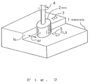
- Figure 2 is a diagram showing the relationship between a tool and a workpiece.
- a tool 2 machines the machining surface 1a of a workpiece 1, wherein the tool 2 travels in the direction shown by the arrow 3 and rotates in the direction shown by the arrow 4. At this time, the tool 2 is deformed by a deformation amount ⁇ , due to the action thereon of a cutting reaction force Fc, in the direction shown by the arrow 5.
- This deformation amount ⁇ is determined by tool deformation parameters and machining conditions.
- the tool deformation parameters include the rigidity Ts of the tool 2 and the hardness Wh of the workpiece 1 and the like, and the machining conditions include a cutting depth ⁇ c, cutting speed f, rpm of a spindle S, and directions of rotation of the spindle Sd (up-cutting) or down-cutting) and the like.
- a tool deformation amount is calculated based on these tool deformation parameters and machining conditions and the tool deformation amount can be corrected, thereby obtain a more accurate machining, by adding the thus determined tool deformation amount to a movement command in the same way as a tool correction amount.
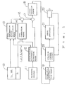
- Figure 1 is a block diagram of a tool deformation amount correction system according to the present invention, where in a preprocessing arithmetic operation means 12 reads a machining program 11 and supplies the machining conditions including the cutting depth ⁇ c, cutting speed f, rpm of a spindle S, and direction of rotation of the spindle Sd and the like to a tool deformation amount calculation means 13, which reads the tool deformation parameters including the rigidity Ts of the tool 2 and the hardness Wh of the workpiece 1 and the like, from a memory 15.
- a preprocessing arithmetic operation means 12 reads a machining program 11 and supplies the machining conditions including the cutting depth ⁇ c, cutting speed f, rpm of a spindle S, and direction of rotation of the spindle Sd and the like to a tool deformation amount calculation means 13, which reads the tool deformation parameters including the rigidity Ts of the tool 2 and the hardness Wh of the workpiece 1 and the like, from a memory 15.
- the tool deformation amount calculation means 13 calculates the tool deformation amount from these tool deformation parameters and machining conditions.
- a calculation formula for determining the tool deformation amount is predetermined by experiments and the like. Further, the calculation formula also can be arranged as a data table in accordance with materials and workpieces.
- a tool correction means 14 reads an offset amount R from the memory 15 and determines an offset vector.
- the tool deformation amount is generally determined as the amount of change of the directions of the offset vector, and as a result, when the offset vector and tool deformation amount are added by an adder 16, an offset vector including the tool deformation amount can be determined.
- This offset vector is added to a movement command from the preprocessing arithmetic operation means 12, by the adder 17, and supplied to an interpolation means 18, which interpolates this value and outputs an interpolation pulse.
- the output interpolation pulse is accelerated or decelerated by a speed acceleration/deceleration means 19 and supplied to a position control circuit 20, which converts the interpolation pulse to a speed command signal and supplies same to a servo amplifier 21, which amplifies this speed command signal to thereby drive a servo motor 22.
- the servo motor 22 contains a pulse coder by which a position feedback pulse is fed back to the position control circuit 20.
- the tool deformation amount is calculated as a component in the same direction as that of the offset vector
- the tool deformation amount may be determined as an independent tool deformation vector and added to the offset vector.
- the present invention can be applied in the same way to a cutting tool used in a lathe.
- the tool correction means determines a tool length as a correction amount
- the tool deformation amount is determined as a Z-axis component and Y-axis component (vertical component).
- the Z-axis component can be corrected in the same way as a usual tool length correction, but the Y-axis component must be corrected by being converted into an X-axis component.
- a tool deformation amount is calculated from tool deformation parameters and machining conditions, and then corrected, a machining can be accurately carried out, and thus a trial cutting becomes unnecessary, and accordingly, the machining time can be shortened.
Abstract
Description
- The present invention relates to a system for correcting a tool deformation amount by which the amount of deformation of a tool is corrected for machining, and more specifically, to a system for correcting an amount of deformation of a tool by which the tool deformation amount is determined from the rigidity and the like of the tool.
- When a workpiece is machined by a tool, the tool is deformed by a predetermined amount by a cutting reaction force acting thereon, and therefore, a greater machining accuracy can be obtained by correcting this tool deformation amount, even in a numerically controlled machine tool. In general, a tool deformation amount is processed by the operator based on personal experience, together with a tool length correction amount and tool diameter correction amount, and the like.
- A problem arises, however, in that although an experienced operator can accurately estimate a tool deformation amount, an operator having little experience cannot do so, and even an experienced operator cannot accurately determine a tool deformation amount when a new workpiece is machined.
- As is well known. a tool deformation amount can be accurately determined by using a method of a trial cutting of a workpiece, but much time is lost if a trial cutting must be carried out every time, and further when an expensive workpiece is involved, the trial cutting is undesirable.
- JP-A-57138562 discloses a tool holder which, in order to compensate for machining errors, has a memory containing tool correction information. ZWF, Zeitschrift Fur Wirtschaftliche Fertigung und Automatisierung, No2, Feb 1990, Munich, pages 86 to 90, discloses a machining system providing parameter storage. Taking the above into consideration, an object of the present invention is to provide a tool deformation amount correction system by which a tool deformation amount can be accurately determined thereby to carry out an accurate machining.
- To attain the above object, according to the present invention, there is provided a system for correcting a tool deformation amount by which the amount of deformation of a tool is corrected for machining, comprising:
a memory for storing tool deformation parameters for calculating a tool deformation amount;
a tool correction means for calculating a tool correction amount;
an adder for adding said tool correction amount to a movement command and determining an amount of movement; and
an interpolation means for interpolating said amount of movement; characterised by:
a preprocessing arithmetic operation means for reading a machining program and outputting machining conditions;
a tool deformation amount calculation means for determining the tool deformation amount from said tool deformation parameters and said machining conditions; and
the adder also adding the tool deformation amount to the movement command. - The tool deformation amount calculation means reads the tool deformation parameters such as the rigidity of the tool and the like from the memory, the preprocessing arithmetic operation means reads the machining program and supplies the machining conditions such as a cutting speed and the like necessary for the calculation of the tool deformation amount to the tool deformation amount calculation means, and the tool deformation amount calculation means calculates the tool deformation amount from the tool deformation parameters and machining conditions. Further, the tool correction means determines the tool correction amount, and the tool deformation amount and tool correction amount are added to the movement command to determine the amount of movement interpolated by the interpolation means.
- In the drawings:-
- Figure 1 is a block diagram of a tool deformation amount correction system according to the present invention; and
- Figure 2 is a diagram showing the relationship between a tool and a workpiece.
- An embodiment of the present invention will be described below with reference to the drawings.
- Figure 2 is a diagram showing the relationship between a tool and a workpiece. A
tool 2 machines the machining surface 1a of aworkpiece 1, wherein thetool 2 travels in the direction shown by thearrow 3 and rotates in the direction shown by thearrow 4. At this time, thetool 2 is deformed by a deformation amount δ, due to the action thereon of a cutting reaction force Fc, in the direction shown by thearrow 5. - This deformation amount δ is determined by tool deformation parameters and machining conditions. The tool deformation parameters include the rigidity Ts of the
tool 2 and the hardness Wh of theworkpiece 1 and the like, and the machining conditions include a cutting depth Δc, cutting speed f, rpm of a spindle S, and directions of rotation of the spindle Sd (up-cutting) or down-cutting) and the like. - Therefore, a tool deformation amount is calculated based on these tool deformation parameters and machining conditions and the tool deformation amount can be corrected, thereby obtain a more accurate machining, by adding the thus determined tool deformation amount to a movement command in the same way as a tool correction amount.
- Figure 1 is a block diagram of a tool deformation amount correction system according to the present invention, where in a preprocessing arithmetic operation means 12 reads a machining program 11 and supplies the machining conditions including the cutting depth Δc, cutting speed f, rpm of a spindle S, and direction of rotation of the spindle Sd and the like to a tool deformation amount calculation means 13, which reads the tool deformation parameters including the rigidity Ts of the
tool 2 and the hardness Wh of theworkpiece 1 and the like, from amemory 15. - The tool deformation amount calculation means 13 calculates the tool deformation amount from these tool deformation parameters and machining conditions.
- A calculation formula for determining the tool deformation amount is predetermined by experiments and the like. Further, the calculation formula also can be arranged as a data table in accordance with materials and workpieces.
- Further, a tool correction means 14 reads an offset amount R from the
memory 15 and determines an offset vector. The tool deformation amount is generally determined as the amount of change of the directions of the offset vector, and as a result, when the offset vector and tool deformation amount are added by anadder 16, an offset vector including the tool deformation amount can be determined. - This offset vector is added to a movement command from the preprocessing arithmetic operation means 12, by the
adder 17, and supplied to an interpolation means 18, which interpolates this value and outputs an interpolation pulse. - The output interpolation pulse is accelerated or decelerated by a speed acceleration/deceleration means 19 and supplied to a
position control circuit 20, which converts the interpolation pulse to a speed command signal and supplies same to a servo amplifier 21, which amplifies this speed command signal to thereby drive aservo motor 22. Theservo motor 22 contains a pulse coder by which a position feedback pulse is fed back to theposition control circuit 20. - In Figure 1, the speed acceleration/deceleration means 19,
position control circuit 20, servo amplifier 21 andservo motor 22 are shown as an element for a single axis and the elements for other axes are not shown at these elements have the same arrangement as described above. Further, a spindle amplifier, spindle motor and the like are not shown in Figure 1. - Although in the above description, the tool deformation amount is calculated as a component in the same direction as that of the offset vector, the tool deformation amount may be determined as an independent tool deformation vector and added to the offset vector.
- Note, although the above example is described as a tool deformation amount for a milling cutter used in a machining center of the like, the present invention can be applied in the same way to a cutting tool used in a lathe. In this case, however, the tool correction means determines a tool length as a correction amount, and further, the tool deformation amount is determined as a Z-axis component and Y-axis component (vertical component). The Z-axis component can be corrected in the same way as a usual tool length correction, but the Y-axis component must be corrected by being converted into an X-axis component.
- As described above, according to the present invention, since a tool deformation amount is calculated from tool deformation parameters and machining conditions, and then corrected, a machining can be accurately carried out, and thus a trial cutting becomes unnecessary, and accordingly, the machining time can be shortened.
Claims (7)
- A system for correcting a tool deformation amount by which the amount of deformation of a tool (2) is corrected for machining, comprising:
a memory (15) for storing tool deformation parameters for calculating a tool deformation amount;
a tool correction means (14) for calculating a tool correction amount;
an adder (17) for adding said tool correction amount to a movement command and determining an amount of movement; and
an interpolation means (18) for interpolating said amount of movement; characterised by:
a preprocessing arithmetic operation means (12) for reading a machining program and outputting machining conditions;
a tool deformation amount calculation means (13) for determining the tool deformation amount from said tool deformation parameters and said machining conditions; and
the adder (17) also adding the tool deformation amount to the movement command. - A system for correcting a tool deformation amount according to claim 1, wherein said tool deformation parameters include at least one of a rigidity of a tool (2) and a hardness of a workpiece (1).
- A system for correcting a tool deformation amount according to claim 1, wherein said machining conditions include at least one of a cutting depth, a cutting speed, an rpm of a spindle (5) and a direction of rotation of the spindle.
- A system for correcting a tool deformation amount according to claim 1, wherein said tool (2) is a milling tool and said tool correction means (14) is a tool path correction means.
- A system for correcting a tool deformation amount according to claim 4, wherein said tool deformation amount is determined as an amount of change of a direction of an offset vector.
- A system for correcting a tool deformation amount according to claim 1, wherein said tool (2) is a cutting tool and said tool correction means (14) is a tool length correction means.
- A system for correcting a tool deformation amount according to claim 6, wherein a Y-axis deformation component of said tool deformation amount is converted into an X-axis component.
Applications Claiming Priority (3)
| Application Number | Priority Date | Filing Date | Title |
|---|---|---|---|
| JP2162087A JPH0452908A (en) | 1990-06-20 | 1990-06-20 | Tool deformation correcting system |
| JP162087/90 | 1990-06-20 | ||
| PCT/JP1991/000753 WO1991019592A1 (en) | 1990-06-20 | 1991-06-04 | System for correcting quantity of deformation of tool |
Publications (3)
| Publication Number | Publication Date |
|---|---|
| EP0487738A1 EP0487738A1 (en) | 1992-06-03 |
| EP0487738A4 EP0487738A4 (en) | 1992-08-19 |
| EP0487738B1 true EP0487738B1 (en) | 1996-01-03 |
Family
ID=15747838
Family Applications (1)
| Application Number | Title | Priority Date | Filing Date |
|---|---|---|---|
| EP91910154A Expired - Lifetime EP0487738B1 (en) | 1990-06-20 | 1991-06-04 | System for correcting quantity of deformation of tool |
Country Status (5)
| Country | Link |
|---|---|
| US (1) | US5479353A (en) |
| EP (1) | EP0487738B1 (en) |
| JP (1) | JPH0452908A (en) |
| DE (1) | DE69116112T2 (en) |
| WO (1) | WO1991019592A1 (en) |
Families Citing this family (10)
| Publication number | Priority date | Publication date | Assignee | Title |
|---|---|---|---|---|
| JPH087614B2 (en) * | 1992-03-27 | 1996-01-29 | 株式会社牧野フライス製作所 | Method and device for correcting tool length of machine tool |
| US5621294A (en) * | 1995-11-21 | 1997-04-15 | Universal Instruments Corporation | Apparatus and method for force compensation in a variable reluctance motor |
| AU762544B2 (en) * | 1997-06-30 | 2003-06-26 | Fuji Photo Film Co., Ltd. | Image communication system and method |
| US6582166B1 (en) | 1999-10-22 | 2003-06-24 | Gerber Scientific Products, Inc. | Method of compensating for cutter deflection |
| CA2427702A1 (en) * | 2000-11-03 | 2002-05-10 | Synthes (U.S.A.) | Determination of deformations of surgical tools |
| JP4778631B2 (en) * | 2001-05-15 | 2011-09-21 | 富士重工業株式会社 | Test model movement simulation test method and apparatus |
| US20030163147A1 (en) * | 2002-02-22 | 2003-08-28 | Rabiner Robert A. | Apparatus and method for using a vascular introducer with an ultrasonic probe |
| DE112006004054A5 (en) * | 2006-07-28 | 2009-07-02 | Siemens Aktiengesellschaft | Position-dependent compliance compensation in a machine tool |
| JP5465922B2 (en) * | 2009-05-15 | 2014-04-09 | Dmg森精機株式会社 | Processing method and processing system |
| JP6011353B2 (en) * | 2013-01-17 | 2016-10-19 | 日立金属株式会社 | Machining condition prediction apparatus and machining condition prediction method |
Family Cites Families (13)
| Publication number | Priority date | Publication date | Assignee | Title |
|---|---|---|---|---|
| AU461290B2 (en) * | 1970-12-29 | 1975-05-22 | Toshiba Machine Co. Ltd. | Method and apparatus for in-feed control for improving the accuracy of machining of a workpiece |
| US4031368A (en) * | 1972-04-17 | 1977-06-21 | Verkstadsteknik Ab | Adaptive control of cutting machining operations |
| US4078195A (en) * | 1976-01-13 | 1978-03-07 | Macotech Corporation | Adaptive control system for numerically controlled machine tools |
| JPS5341872A (en) * | 1976-09-29 | 1978-04-15 | Okuma Mach Works Ltd | System for automatically controlling serviceable life of tools |
| IT1165014B (en) * | 1979-03-27 | 1987-04-22 | Innocenti Santeustacchio Spa | GEOMETRIC CONTROL SYSTEM, TO INCREASE THE ACCURACY OF A MACHINE TOOL, PARTICULARLY OF A LARGE DIMENSION MACHINE TOOL |
| JPS57138562A (en) * | 1981-02-20 | 1982-08-26 | Okuma Mach Works Ltd | Correction device for tool |
| US4620281A (en) * | 1981-09-22 | 1986-10-28 | General Electric Company | In-process cutting tool condition compensation and part inspection |
| JPS5981705A (en) * | 1982-11-02 | 1984-05-11 | Fanuc Ltd | Compensating method of nc machine tool |
| JPS59212909A (en) * | 1983-05-17 | 1984-12-01 | Toyoda Mach Works Ltd | Correction controller for size of tool |
| JPS6179549A (en) * | 1984-09-28 | 1986-04-23 | Takaaki Nagao | Curved surface working device |
| JPS62213945A (en) * | 1986-03-12 | 1987-09-19 | Toshiba Mach Co Ltd | Thermal displacement correcting device for machine tool |
| JPS63272447A (en) * | 1987-04-30 | 1988-11-09 | Mitsubishi Heavy Ind Ltd | Feed controller equipped with correction for deflection quantity |
| US5025592A (en) * | 1988-05-09 | 1991-06-25 | Brother Kogyo Kabushiki Kaisha | Machine tool having workpiece machining dimension and tool length measuring functions |
-
1990
- 1990-06-20 JP JP2162087A patent/JPH0452908A/en active Pending
-
1991
- 1991-06-04 EP EP91910154A patent/EP0487738B1/en not_active Expired - Lifetime
- 1991-06-04 WO PCT/JP1991/000753 patent/WO1991019592A1/en active IP Right Grant
- 1991-06-04 US US07/828,971 patent/US5479353A/en not_active Expired - Fee Related
- 1991-06-04 DE DE69116112T patent/DE69116112T2/en not_active Expired - Fee Related
Also Published As
| Publication number | Publication date |
|---|---|
| DE69116112T2 (en) | 1996-05-15 |
| WO1991019592A1 (en) | 1991-12-26 |
| EP0487738A1 (en) | 1992-06-03 |
| JPH0452908A (en) | 1992-02-20 |
| US5479353A (en) | 1995-12-26 |
| DE69116112D1 (en) | 1996-02-15 |
| EP0487738A4 (en) | 1992-08-19 |
Similar Documents
| Publication | Publication Date | Title |
|---|---|---|
| US6097168A (en) | Position control apparatus and method of the same, numerical control program preparation apparatus and method of the same, and methods of controlling numerical control machine tool | |
| KR100354878B1 (en) | Servo control method for orbital machining with cutting tool and servo control system for orbital machining | |
| US5404308A (en) | Numerical control (NC) device to control feed speed of tool based on speed of spindle and amount of change of spindle speed | |
| EP0268887B1 (en) | Numerical control feed device for machine tool | |
| EP0098309B1 (en) | Numerical control machining system | |
| GB1395683A (en) | Closed loop control system | |
| EP0487738B1 (en) | System for correcting quantity of deformation of tool | |
| JPH0736514A (en) | Three-dimensional tool diameter correction system | |
| JP4796936B2 (en) | Processing control device | |
| CA1334864C (en) | Method and system for controlling a machine tool such as a turning machine | |
| EP0453571A1 (en) | Method of correcting positional fluctuations of machine | |
| JPH04323705A (en) | Synchronous repeat control system for rotation axis | |
| US20200174440A1 (en) | Numerical control device, program recording medium and control method | |
| JP4982170B2 (en) | Machining control device and machining control program | |
| JP5334932B2 (en) | Parameter setting method and parameter setting device | |
| JP2800124B2 (en) | Control method of numerically controlled machine tool and control device therefor | |
| JP3454616B2 (en) | Method and apparatus for controlling feed axis of NC machine tool | |
| JP4036502B2 (en) | NC program creation method, creation device, and NC machine tool control method | |
| JPH044405A (en) | Numerical controller | |
| JPS6239160A (en) | Machine tool with nc device | |
| JPS6299020A (en) | Thread cutting control system | |
| JPS62176739A (en) | Straightness correction device for machine tool | |
| JP2579911B2 (en) | High-speed NC processing machine by copying operation | |
| JP2926524B2 (en) | Numerical controller with trial cutting function | |
| JP2709056B2 (en) | Position control method |
Legal Events
| Date | Code | Title | Description |
|---|---|---|---|
| PUAI | Public reference made under article 153(3) epc to a published international application that has entered the european phase |
Free format text: ORIGINAL CODE: 0009012 |
|
| 17P | Request for examination filed |
Effective date: 19920311 |
|
| AK | Designated contracting states |
Kind code of ref document: A1 Designated state(s): DE FR IT |
|
| A4 | Supplementary search report drawn up and despatched |
Effective date: 19920702 |
|
| AK | Designated contracting states |
Kind code of ref document: A4 Designated state(s): DE FR IT |
|
| 17Q | First examination report despatched |
Effective date: 19940629 |
|
| GRAA | (expected) grant |
Free format text: ORIGINAL CODE: 0009210 |
|
| AK | Designated contracting states |
Kind code of ref document: B1 Designated state(s): DE FR IT |
|
| PG25 | Lapsed in a contracting state [announced via postgrant information from national office to epo] |
Ref country code: FR Effective date: 19960103 |
|
| REF | Corresponds to: |
Ref document number: 69116112 Country of ref document: DE Date of ref document: 19960215 |
|
| ITF | It: translation for a ep patent filed |
Owner name: JACOBACCI & PERANI S.P.A. |
|
| EN | Fr: translation not filed | ||
| PGFP | Annual fee paid to national office [announced via postgrant information from national office to epo] |
Ref country code: DE Payment date: 19960612 Year of fee payment: 6 |
|
| PLBE | No opposition filed within time limit |
Free format text: ORIGINAL CODE: 0009261 |
|
| STAA | Information on the status of an ep patent application or granted ep patent |
Free format text: STATUS: NO OPPOSITION FILED WITHIN TIME LIMIT |
|
| 26N | No opposition filed | ||
| PG25 | Lapsed in a contracting state [announced via postgrant information from national office to epo] |
Ref country code: DE Free format text: LAPSE BECAUSE OF NON-PAYMENT OF DUE FEES Effective date: 19980303 |
|
| PG25 | Lapsed in a contracting state [announced via postgrant information from national office to epo] |
Ref country code: IT Free format text: LAPSE BECAUSE OF NON-PAYMENT OF DUE FEES Effective date: 20050604 |