EP0487564B1 - Stethoscope - Google Patents
Stethoscope Download PDFInfo
- Publication number
- EP0487564B1 EP0487564B1 EP90911897A EP90911897A EP0487564B1 EP 0487564 B1 EP0487564 B1 EP 0487564B1 EP 90911897 A EP90911897 A EP 90911897A EP 90911897 A EP90911897 A EP 90911897A EP 0487564 B1 EP0487564 B1 EP 0487564B1
- Authority
- EP
- European Patent Office
- Prior art keywords
- pickup
- acoustic
- stethoscope
- operatively
- acoustic signals
- Prior art date
- Legal status (The legal status is an assumption and is not a legal conclusion. Google has not performed a legal analysis and makes no representation as to the accuracy of the status listed.)
- Expired - Lifetime
Links
- 230000004071 biological effect Effects 0.000 claims description 19
- 230000000694 effects Effects 0.000 claims description 11
- 238000004519 manufacturing process Methods 0.000 claims 3
- 230000000747 cardiac effect Effects 0.000 claims 2
- 239000002184 metal Substances 0.000 claims 2
- 238000000034 method Methods 0.000 claims 2
- 230000002708 enhancing effect Effects 0.000 claims 1
- 238000001914 filtration Methods 0.000 claims 1
- 230000003190 augmentative effect Effects 0.000 abstract description 12
- 238000001514 detection method Methods 0.000 description 7
- 239000012528 membrane Substances 0.000 description 2
- 230000037361 pathway Effects 0.000 description 2
- 239000004033 plastic Substances 0.000 description 2
- 238000000718 qrs complex Methods 0.000 description 2
- 239000002033 PVDF binder Substances 0.000 description 1
- 230000003044 adaptive effect Effects 0.000 description 1
- 239000000853 adhesive Substances 0.000 description 1
- 230000001070 adhesive effect Effects 0.000 description 1
- 230000005540 biological transmission Effects 0.000 description 1
- 238000010586 diagram Methods 0.000 description 1
- 238000012544 monitoring process Methods 0.000 description 1
- 229910000510 noble metal Inorganic materials 0.000 description 1
- 229920002981 polyvinylidene fluoride Polymers 0.000 description 1
- 230000001960 triggered effect Effects 0.000 description 1
Images

Classifications
-
- A—HUMAN NECESSITIES
- A61—MEDICAL OR VETERINARY SCIENCE; HYGIENE
- A61B—DIAGNOSIS; SURGERY; IDENTIFICATION
- A61B7/00—Instruments for auscultation
- A61B7/02—Stethoscopes
-
- A—HUMAN NECESSITIES
- A61—MEDICAL OR VETERINARY SCIENCE; HYGIENE
- A61B—DIAGNOSIS; SURGERY; IDENTIFICATION
- A61B5/00—Measuring for diagnostic purposes; Identification of persons
- A61B5/24—Detecting, measuring or recording bioelectric or biomagnetic signals of the body or parts thereof
- A61B5/25—Bioelectric electrodes therefor
- A61B5/279—Bioelectric electrodes therefor specially adapted for particular uses
- A61B5/28—Bioelectric electrodes therefor specially adapted for particular uses for electrocardiography [ECG]
- A61B5/282—Holders for multiple electrodes
-
- A—HUMAN NECESSITIES
- A61—MEDICAL OR VETERINARY SCIENCE; HYGIENE
- A61B—DIAGNOSIS; SURGERY; IDENTIFICATION
- A61B5/00—Measuring for diagnostic purposes; Identification of persons
- A61B5/24—Detecting, measuring or recording bioelectric or biomagnetic signals of the body or parts thereof
- A61B5/316—Modalities, i.e. specific diagnostic methods
- A61B5/318—Heart-related electrical modalities, e.g. electrocardiography [ECG]
- A61B5/346—Analysis of electrocardiograms
- A61B5/349—Detecting specific parameters of the electrocardiograph cycle
- A61B5/352—Detecting R peaks, e.g. for synchronising diagnostic apparatus; Estimating R-R interval
Landscapes
- Health & Medical Sciences (AREA)
- Life Sciences & Earth Sciences (AREA)
- Cardiology (AREA)
- Veterinary Medicine (AREA)
- Animal Behavior & Ethology (AREA)
- Physics & Mathematics (AREA)
- Engineering & Computer Science (AREA)
- Biomedical Technology (AREA)
- Heart & Thoracic Surgery (AREA)
- Medical Informatics (AREA)
- Molecular Biology (AREA)
- Surgery (AREA)
- Public Health (AREA)
- General Health & Medical Sciences (AREA)
- Biophysics (AREA)
- Pathology (AREA)
- Acoustics & Sound (AREA)
- Measuring Pulse, Heart Rate, Blood Pressure Or Blood Flow (AREA)
- Materials For Medical Uses (AREA)
- Headphones And Earphones (AREA)
Abstract
Description
- This invention relates to stethoscopes.
- Many of the sounds detected by a stethoscope are faint or fall outside the human auditory range and, therefore, are not effectively perceived by clinicians.
- As explained in more detail below we have designed a stethoscope which provides a listener with access to combined unmodified, high audibility acoustic signals and electronically enhanced signals corresponding to acoustic signals originally outside the human auditory range, when the stethoscope is operated in an augmented mode. These originally inaudible sounds are brought into the human auditory range with an electrical pickup and associated signal processing circuitry which raise the audibility of low frequency signals by optionally multiplying or doubling their frequencies, filter the frequency boosted signals to remove higher order harmonics which are an artifact of the signal processing, and amplify these signals to optimize audibility.
- US-A-4 821 327 of Furugard discloses a stethoscope as set out in the preamble of both
Claims 1 and 21 of this application. The electrical-to-acoustic converter of this US Patent is arranged to provide a synthetic continuous tone when sound, such as Korotkoff noise which occurs in a frequency range of relatively low audibility, is detected. - According to a first aspect of this invention, we accordingly provide a stethoscope comprising: a first pickup adapted operatively to generate first acoustic signals representative of biological activity in a frequency range that includes frequencies of relatively high audibility; a second pickup adapted operatively to generate electrical signals representative of biological activity in a frequency range that includes frequencies of relatively low audibility; an electrical-to-acoustic converter adapted operatively to produce second acoustic signals of enhanced audibility corresponding to said frequencies of relatively low audibility; and a transmitter adapted operatively to transmit to a listener the combination of said first and second acoustic signals; the stethoscope being characterised in that the said second acoustic signals which said converter is adapted to produce resemble the sounds of said biological activity in said frequency range of relatively low audibility.
- In a second and alternative aspect of this invention, we provide a stethoscope comprising: a pickup adapted operatively to generate first acoustic signals representative of biological activity; a second pickup adapted operatively to generate electrical signals representative of heart activity during a heart cycle; an electrical-to-acoustic converter adapted operatively to produce a second acoustic signal in response to said electrical signals; and a transmitter adapted operatively to transmit to a listener the combination of said first acoustic signals and said second acoustic signal; characterised in that said converter is adapted to produce said second acoustic signal as a signal representative of heart activity which gives an indication of timing of said heart cycle, whereby said combination of said first acoustic signals and said second acoustic signal is effective to assist the listener in determining when during said heart cycle said first acoustic signals occur.
- We describe below a QRS triggered acoustic timing signal generator which produces an acoustic timing signal to assist the clinician in determining when particular sounds occur in the heart cycle. In preferred embodiments, this acoustic timing signal may be activated with or independently of low audibility signal enhancement. In a preferred embodiment, pickups for generating electrical signals representative of heart activity, for QRS detection and
acoustic timing signal triggering are integrated with the stethoscope diaphragm, along with the electrical pickup. - In the drawings;
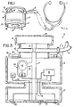
- Fig. 1 is a somewhat schematic side view of an electronically augmented stethoscope embodying the invention;
- Fig. 2 is a block diagram of the electronic circuitry of the stethoscope of Fig. 1;
- Fig. 3 is a partially schematic cross section of the bell portion of the stethoscope of Fig. 1.
- Referring to Fig. 1, stethoscope 10 consists of
bell assembly 12 andrubber tubes 14 for sound transmission toheadset 16.Bell assembly 12 integrateselectronics module 18, which encloses electronic signal processing circuitry described in detail below. Valveassembly 13 connects withtubes 14 and upper acoustic pathway 15 (Fig. 3). Upperacoustic chamber 19 screws into the top ofassembly 13 andmodule 18 screws into the bottom ofassembly 13.Assembly 13 is rotated to allow body sound pickup from eitherchamber 19 which includesplastic membrane diaphragm 20 orlower bell assembly 21, which contains components for acoustic and electronic sound and electrocardiogram pick-up. - Within the
lower bell assembly 21 isplastic membrane diaphragm 22 to whichpiezoelectric transducer 24 is fastened with an adhesive.Transducer 24 is a polarized polyvinylidene fluoride film sufficiently thin and compliant to insure unimpaired sound response ofdiaphragm 22 and has approximately one-half the diameter ofdiaphragm 22. A pattern of three equally spaced semi-circular noble metal deposits sputtered on todiaphragm 22 serves asECG electrodes 26 for monitoring heart electrical activity. - Referring to Fig. 2,
module 18 includes transducersignal processing circuitry 27, ECG andQRS detection circuitry 28, andheadset driver 29. On the outside of module 18 (Fig. 1),pushbutton 30 activatestransducer circuitry 27,volume control knob 31 adjusts the amplitude of signals emitted bytransducer circuitry 27, and slide switch 32 activatesQRS detection circuitry 28. - When
transducer circuitry 27 is activated, transducer 24 converts vibrations ofdiaphragm 22 into electrical signals. Referring to Fig. 2,lead 33 transmits these signals tobandpass filter 34.Filter 34, a combination of 4 pole high pass and 2 pole low pass Butterworth response filters having a combined response preferably in the range 16-250Hz or in a range as wide as 10-500Hz or as narrow as 30-120Hz, has its output connected toabsolute value circuit 36 for frequency doubling. The frequency doubled signals are filtered by 20 Hz, 2 pole high pass and 200 Hz, 4 pole low pass Butterworthresponse filters 38 and amplified by lownoise amplifier stage 39. Signal amplitude is controlled bypotentiometer 40. - Referring to Fig. 3,
driver 29 includes power amplifier 41 (approx. 100mW) andminiature speaker 42, which acts as an electrical-to-audio transducer, to amplify the electrical signals and convert them to acoustic signals.Driver 29 injects these acoustic signals throughrubber tube connector 43 into loweracoustic pathway 17 where they merge with acoustic signals coupled conventionally, directly fromdiaphragm 22. -
QRS detection circuitry 28 generates a timing sound for determining when sounds occur in the heart cycle.QRS detection circuitry 28 may be enabled independent oftransducer circuitry 27. - Referring to Fig. 2, when
QRS detection circuitry 28 is operated, three ECG leads 46 carry signals to low noise highimpedance instrumentation amplifier 48 whose output is connected to 2 pole,25Hz bandpass filter 50 having Q=1. Adaptive threshold filter 52 recognizes a QRS complex, a narrow, large amplitude signal in the ECG by comparing the peak signal detected to an incoming signal.Pulse generator 54, a one-shot monostable multivibrator, produces a timing pulse each time a QRS complex is detected. Lockout delay circuit 55, a monostable multivibrator with a period of approximately 0.25s, prevents output of spurious timing pulses resulting from noise pickup. Integratedcircuit tone generator 56 sends a tone pulse todriver 29, which produces an acoustic timing signal audible to the clinician. - The described apparatus enables a clinician to use a single stethoscope for both conventional acoustic or electronically augmented modes of operation.
- In the augmented mode, the stethoscope boosts the amplitude of faint sounds and doubles the frequency of low frequency (16-250Hz) sounds so that they are brought within the audible range. Such operation is especially useful for detection of inaudible Korotkoff or heart sounds. The acoustic timing signal aids the clinician in identification of heart sounds detected in the acoustic or augmented mode by relating those heart sounds to the electrical activity of the heart and indicating when they occur in the heart cycle. The apparatus allows the clinician to hear unmodified, familiar audible sound and electronically augmented sounds simultaneously. The combined virtually identical operation of the stethoscope is the acoustic and augmented modes and availability of familiar medium and high frequency sounds enable effective use of the stethoscope in the augmented mode with little additional clinician training.
Claims (28)
- A stethoscope (10) comprising: a first pickup (22) adapted operatively to generate first acoustic signals representative of biological activity in a frequency range that includes frequencies of relatively high audibility; a second pickup (24) adapted operatively to generate electrical signals representative of biological activity in a frequency range that includes frequencies of relatively low audibility; an electrical-to-acoustic converter (27, 29) adapted operatively to produce second acoustic signals of enhanced audibility corresponding to said frequencies of relatively low audibility; and a transmitter (14, 16, 17, 43) adapted operatively to transmit to a listener the combination of said first and second acoustic signals; the stethoscope being characterised in that the said second acoustic signals which said converter (27, 29) is adapted to produce resemble the sounds of said biological activity in said frequency range of relatively low audibility.
- A stethoscope according to Claim 1, characterised in further comprising a first filter (34) adapted for operatively filtering said electrical signals produced by said second pickup to remove said electrical signals representative of biological activity in said frequency range of relatively high audibility.
- A stethoscope according to Claim 2, further characterised in that said first filter (34) is adapted operatively to pass signals in a frequency range between 16Hz and 250Hz.
- A stethoscope according to Claim 2, further characterised in that said first filter (34) is adapted operatively to pass signals in a frequency range between 30Hz and 120Hz.
- A stethoscope according to Claim 2, further characterised in that said first filter (34) is adapted operatively to pass signals in a frequency range between 10Hz and 500Hz.
- A stethoscope according to Claim 2, further characterised in that said converter comprises said first filter (34) and a transducer (42) for converting output of said first filter to said second acoustic signals.
- A stethoscope according to any preceding claim further characterised in that said converter further comprises a frequency booster (36) adapted operatively to increase the frequencies of said electrical signals representative of biological activity to enhance their audibility.
- A stethoscope according to Claim 7, further characterised in that said frequency booster (36) is a frequency multiplier adapted for operatively multiplying the frequencies of said electrical signals representative of biological activity to enhance their audibility.
- A stethoscope according to Claim 8, further characterised in that said frequency multiplier (36) is a frequency doubler adapted to double the frequencies of said electrical signals representative of biological activity to enhance their audibility.
- A stethoscope according to any of Claims 7, 8 or 9 further characterised in that said converter further comprises a second filter (38) adapted operatively to remove higher order harmonics generated by said frequency booster.
- A stethoscope according to any preceding claim, further characterised in that said converter further comprises an amplifier (39) for amplifying said electrical signals representative of biological activity for enhancing audibility.
- A stethoscope according to Claim 11, further characterised in that said converter further comprises a volume control (31) for adjusting the intensity of the amplifier output for optimum audibility.
- A stethoscope according to Claim 1, characterised further in comprising a branch conduit (43) adapted for operatively transmitting said second acoustic signals to a main conduit (17) wherein said first and second acoustic signals are combined.
- A stethoscope according to Claim 1, characterised further in comprising a third pickup (26) adapted operatively to generate electrical signals representative of heart activity.
- A stethoscope according to Claim 14, characterised in further comprising a diaphragm (22) adapted operatively to generate said first acoustic signals, and in that said second pickup (24) and said third pickup (26) are attached to said diaphragm.
- A stethoscope according to Claim 14 or 15, further characterised in that said third pickup comprises three equally spaced metal deposits (26).
- A stethoscope according to Claim 14, further characterised in that said converter further includes circuitry (28) adapted operatively to produce a third acoustic signal in response to said electrical signals representative of heart activity, and in that said transmitter is effective operatively to transmit said third acoustic signal in combination with said first and second acoustic signals.
- A stethoscope according to any of Claims 14, 15 or 16, characterised in further comprising a QRS detector (28) adapted operatively to generate a tone pulse to provide an acoustic timing signal for identifying when heart sounds occur within the cardiac cycle.
- A stethoscope according to Claim 1, characterised further in comprising a third pickup (20) adapted operatively to generate said first acoustic signals as an alternative to said first pickup, said first and third pickups being positioned on said stethoscope so that said first or third pickups can be selectively placed adjacent to a body; and in that said second pickup (24) is disposed near said first pickup (22) and is adapted operatively to generate said electrical signals when said second pickup is placed with said first pickup adjacent to the body; whereby said transmitter (14, 16, 17, 43) is effective to transmit the combination of said first and second acoustic signals when said first pickup and said second pickup are placed adjacent to the body, and to transmit only the first acoustic signals to the listener when said third pickup is placed adjacent to the body.
- A stethoscope according to Claim 19, characterised in further comprising a control device (30) for said electrical-to-acoustic converter that allows a user selectively to activate said converter.
- A stethoscope comprising: a pickup (22) adapted operatively to generate first acoustic signals representative of biological activity; a second pickup (26) adapted operatively to generate electrical signals representative of heart activity during a heart cycle; an electrical-to-acoustic converter (28, 29) adapted operatively to produce a second acoustic signal in response to said electrical signals; and a transmitter (14, 16, 17, 43) adapted operatively to transmit to a listener the combination of said first acoustic signals and said second acoustic signal; characterised in that said converter is adapted to produce said second acoustic signal as a signal representative of heart activity which gives an indication of timing of said heart cycle, whereby said combination of said first acoustic signals and said second acoustic signal is effective to assist the listener in determining when during said heart cycle said first acoustic signals occur.
- A stethoscope according to either Claim 19 or Claim 21, characterised in comprising a diaphragm (22) adapted operatively to generate acoustic signals, and in that said second pickup is attached to said diaphragm for generating said electrical signals.
- A stethoscope according to Claim 22, further characterised in that said second pickup comprises three equally spaced metal deposits (26).
- A stethoscope according to any of Claims 21, 22 or 23, characterised in further comprising a QRS detector (28) adapted to operatively generate a tone pulse to activate production of said second acoustic signal by said electrical-to-acoustic converter for identifying when heart sounds occur in the cardiac cycle.
- A method for producing sound in a stethoscope for listening to biological activity, comprising the steps of: generating first acoustic signals representative of biological activity in a frequency range that includes frequencies of relatively high audibility with a first pickup (22) of the stethoscope; generating electrical signals representative of biological activity in a frequency range that includes frequencies of relatively low audibility with a second pickup (24) of the stethoscope; electrically-to-acoustically converting said electrical signals to second acoustic signals of enhanced audibility that correspond to said frequencies of relatively low audibility and resemble the sounds of said biological activity in said frequency range of relatively low audibility; and transmitting to a listener the combination of said first and second acoustic signals.
- A method according to Claim 25, wherein said first acoustic signals are selectively generated with said first pickup or with a third pickup (20) of said stethoscope that is positioned with respect to said first pickup (22) and said second pickup (24) so that a user can selectively place either: (1) said first pickup and said second pickup together adjacent to a body, or (2) said third pickup adjacent to the body, whereby said first acoustic signals and said second acoustic signals are transmitted together by placing said first pickup (22) and said second pickup (24) adjacent to the body, or only said first acoustic signals are transmitted by placing said third pickup (20) adjacent to the body.
- A method according to Claim 26, wherein said converter is selectively activatable.
- A method for producing sound in a stethoscope for listening to biological activity, comprising the steps of: generating first acoustic signals representative of biological activity with a pickup (22) of said stethoscope; generating electrical signals representative of heart activity during a heart cycle with a second pickup (26) of said stethoscope; electrically-to-acoustically converting said electrical signals representative of heart activity to a second acoustic signal to provide an indication of timing of said heart cycle; and transmitting to a listener the combination of said first acoustic signals and said second acoustic signal to assist the listener in determining when during said heart cycle said first acoustic signals occur.
Applications Claiming Priority (3)
| Application Number | Priority Date | Filing Date | Title |
|---|---|---|---|
| US07/393,781 US5003605A (en) | 1989-08-14 | 1989-08-14 | Electronically augmented stethoscope with timing sound |
| US393781 | 1989-08-14 | ||
| PCT/US1990/004343 WO1991002487A1 (en) | 1989-08-14 | 1990-08-02 | Electronically augmented stethoscope with timing sound |
Publications (3)
| Publication Number | Publication Date |
|---|---|
| EP0487564A1 EP0487564A1 (en) | 1992-06-03 |
| EP0487564A4 EP0487564A4 (en) | 1992-07-08 |
| EP0487564B1 true EP0487564B1 (en) | 1996-01-31 |
Family
ID=23556224
Family Applications (1)
| Application Number | Title | Priority Date | Filing Date |
|---|---|---|---|
| EP90911897A Expired - Lifetime EP0487564B1 (en) | 1989-08-14 | 1990-08-02 | Stethoscope |
Country Status (6)
| Country | Link |
|---|---|
| US (1) | US5003605A (en) |
| EP (1) | EP0487564B1 (en) |
| JP (1) | JPH04507359A (en) |
| AT (1) | ATE133551T1 (en) |
| DE (1) | DE69025191T2 (en) |
| WO (1) | WO1991002487A1 (en) |
Families Citing this family (53)
| Publication number | Priority date | Publication date | Assignee | Title |
|---|---|---|---|---|
| US5365937A (en) * | 1992-09-09 | 1994-11-22 | Mcg International, Inc. | Disposable sensing device with contaneous conformance |
| KR950703891A (en) * | 1992-12-07 | 1995-11-17 | 안드레드 빌러스 | Electronic Stethoscope |
| US5347583A (en) * | 1992-12-16 | 1994-09-13 | Minnesota Mining And Manufacturing Company | Electronic stethoscope having binaural earpiece |
| DK63193D0 (en) * | 1993-06-02 | 1993-06-02 | Bang & Olufsen Tech As | HEART SIGNAL MEASUREMENT APPARATUS |
| US7006638B1 (en) | 1994-08-30 | 2006-02-28 | Bang & Olufsen Technology A/S | Electronic stethoscope |
| DE59604310D1 (en) * | 1995-07-06 | 2000-03-02 | Caditec Ag Rotkreuz | ELECTRONIC STETHOSCOPE |
| US6002777A (en) * | 1995-07-21 | 1999-12-14 | Stethtech Corporation | Electronic stethoscope |
| EP0845958B1 (en) * | 1995-07-21 | 2003-05-28 | Stethtech Corporation | Electronic stethoscope |
| US6026170A (en) * | 1995-11-27 | 2000-02-15 | Minnesota Mining And Manufacturing Company | Electronic stethoscope with idealized bell and idealized diaphragm modes |
| US6050950A (en) | 1996-12-18 | 2000-04-18 | Aurora Holdings, Llc | Passive/non-invasive systemic and pulmonary blood pressure measurement |
| US6193668B1 (en) * | 1997-11-10 | 2001-02-27 | Medacoustics, Inc. | Acoustic sensor array for non-invasive detection of coronary artery disease |
| US6278890B1 (en) | 1998-11-09 | 2001-08-21 | Medacoustics, Inc. | Non-invasive turbulent blood flow imaging system |
| US6311155B1 (en) | 2000-02-04 | 2001-10-30 | Hearing Enhancement Company Llc | Use of voice-to-remaining audio (VRA) in consumer applications |
| CN1116737C (en) * | 1998-04-14 | 2003-07-30 | 听觉增强有限公司 | User adjustable volume control that accommodates hearing |
| US7415120B1 (en) | 1998-04-14 | 2008-08-19 | Akiba Electronics Institute Llc | User adjustable volume control that accommodates hearing |
| US6261237B1 (en) | 1998-08-20 | 2001-07-17 | Medacoustics, Inc. | Thin film piezoelectric polymer sensor |
| US6985594B1 (en) | 1999-06-15 | 2006-01-10 | Hearing Enhancement Co., Llc. | Voice-to-remaining audio (VRA) interactive hearing aid and auxiliary equipment |
| US6442278B1 (en) | 1999-06-15 | 2002-08-27 | Hearing Enhancement Company, Llc | Voice-to-remaining audio (VRA) interactive center channel downmix |
| US7266501B2 (en) * | 2000-03-02 | 2007-09-04 | Akiba Electronics Institute Llc | Method and apparatus for accommodating primary content audio and secondary content remaining audio capability in the digital audio production process |
| US6351733B1 (en) | 2000-03-02 | 2002-02-26 | Hearing Enhancement Company, Llc | Method and apparatus for accommodating primary content audio and secondary content remaining audio capability in the digital audio production process |
| US6726635B1 (en) * | 2000-05-12 | 2004-04-27 | Lasala Anthony F. | Cardiac impulse detector |
| US20040260193A1 (en) * | 2000-05-12 | 2004-12-23 | Lasala Anthony F. | Cardiac impulse detector |
| US20040096065A1 (en) * | 2000-05-26 | 2004-05-20 | Vaudrey Michael A. | Voice-to-remaining audio (VRA) interactive center channel downmix |
| US6999592B2 (en) * | 2002-08-08 | 2006-02-14 | Chelen William E | Time and frequency windowed pocket cardiac stethoscope |
| US20040032957A1 (en) * | 2002-08-14 | 2004-02-19 | Mansy Hansen A. | Sensors and sensor assemblies for monitoring biological sounds and electric potentials |
| US6790184B2 (en) * | 2002-09-05 | 2004-09-14 | Sure-Shot Medical Device, Inc. | Device for medical percussion |
| US7285098B2 (en) * | 2002-09-05 | 2007-10-23 | Sure-Shot Medical Device, Inc. | Device for medical percussion |
| US7533758B1 (en) | 2004-09-08 | 2009-05-19 | Abraham Jacobo Frech | Apparatus and method for auscultation and percussion of a human or animal body |
| SE528409C2 (en) * | 2005-02-21 | 2006-11-07 | Computerized Medical Technolog | Electronic sound monitor for use as stethoscope, has vibration transducer adapted to transform vibrations to electrical signals and arranged in bell-shaped vibration collecting structure |
| US20080228095A1 (en) * | 2007-03-15 | 2008-09-18 | Richardson Mary | Medical device |
| EP2136711A1 (en) * | 2007-03-23 | 2009-12-30 | 3M Innovative Properties Company | Modular electronic biosensor with interface for receiving disparate modules |
| US8771204B2 (en) * | 2008-12-30 | 2014-07-08 | Masimo Corporation | Acoustic sensor assembly |
| WO2011047216A2 (en) | 2009-10-15 | 2011-04-21 | Masimo Corporation | Physiological acoustic monitoring system |
| US8821415B2 (en) | 2009-10-15 | 2014-09-02 | Masimo Corporation | Physiological acoustic monitoring system |
| US8790268B2 (en) | 2009-10-15 | 2014-07-29 | Masimo Corporation | Bidirectional physiological information display |
| US8715206B2 (en) * | 2009-10-15 | 2014-05-06 | Masimo Corporation | Acoustic patient sensor |
| US9326712B1 (en) | 2010-06-02 | 2016-05-03 | Masimo Corporation | Opticoustic sensor |
| KR101178867B1 (en) | 2011-03-30 | 2012-09-03 | 김주한 | Telemedical stethoscope |
| US9192351B1 (en) | 2011-07-22 | 2015-11-24 | Masimo Corporation | Acoustic respiratory monitoring sensor with probe-off detection |
| EP3603502B1 (en) | 2011-10-13 | 2023-10-04 | Masimo Corporation | Physiological acoustic monitoring system |
| CN102599928B (en) * | 2012-03-06 | 2013-10-30 | 温州康诺克医疗器械有限公司 | Frequency testing system of stethoscope |
| US9955937B2 (en) | 2012-09-20 | 2018-05-01 | Masimo Corporation | Acoustic patient sensor coupler |
| CN104510492A (en) * | 2013-10-06 | 2015-04-15 | 吴伟 | Method and device for auscultating inaudible signals |
| US10828007B1 (en) | 2013-10-11 | 2020-11-10 | Masimo Corporation | Acoustic sensor with attachment portion |
| RU2553210C1 (en) * | 2013-11-12 | 2015-06-10 | Общество с ограниченной ответственностью "Научно-производственное предприятие "Волготех" | Method of measuring arterial pressure by korotkov method and device for its realisation |
| US9445779B2 (en) * | 2014-10-02 | 2016-09-20 | The United States Of America As Represented By The Administrator Of The National Aeronautics And Space Administration | Infrasonic stethoscope for monitoring physiological processes |
| CA3078227A1 (en) | 2017-10-04 | 2019-04-11 | Ausculsciences, Inc. | Auscultatory sound-or-vibration sensor |
| US20190117165A1 (en) | 2017-10-20 | 2019-04-25 | Jikang ZENG | Coronary artery disease detection signal processing system and method |
| US11284827B2 (en) | 2017-10-21 | 2022-03-29 | Ausculsciences, Inc. | Medical decision support system |
| JPWO2021020202A1 (en) * | 2019-07-26 | 2021-02-04 | ||
| CN113616233A (en) * | 2020-05-06 | 2021-11-09 | 北京金航道科技有限公司 | Sound pickup method of stethoscope and stethoscope |
| CN215227799U (en) * | 2020-12-15 | 2021-12-21 | 深圳邦健生物医疗设备股份有限公司 | Digital stethoscope |
| WO2022232131A1 (en) * | 2021-04-26 | 2022-11-03 | Emory University | Handheld auscultation systems, devices, and methods |
Family Cites Families (33)
| Publication number | Priority date | Publication date | Assignee | Title |
|---|---|---|---|---|
| US3110770A (en) * | 1959-09-04 | 1963-11-12 | Faraday Electronic Instr Ltd | Apparatus for use in stethoscopy |
| US3247324A (en) * | 1964-06-26 | 1966-04-19 | Cefaly | Acoustic and electronic stethoscope |
| US3539724A (en) * | 1967-07-03 | 1970-11-10 | Daniel C Keesee | Combination electronic and air-column actuated stethoscope |
| NL7004341A (en) * | 1970-03-25 | 1971-09-28 | ||
| US3651798A (en) * | 1970-05-15 | 1972-03-28 | Parke Davis & Co | Blood pressure indicator and noise |
| US3858005A (en) * | 1973-11-15 | 1974-12-31 | Marshall R | Stethoscope with display |
| US3989895A (en) * | 1974-05-08 | 1976-11-02 | Daniel Sr Philip S O | Stethoscope transducer |
| US4048444A (en) * | 1975-08-15 | 1977-09-13 | Giampapa Vincent C | Phonostethoscope conversion unit for amplification and clarification of corporeal sounds |
| FR2330367A1 (en) * | 1975-11-04 | 1977-06-03 | Sephadem | Electronic cardiac and pulmonary stethoscope - has moving coil electrodynamic VLF ejector working under pressure |
| US4071694A (en) * | 1976-08-31 | 1978-01-31 | Minnesota Mining And Manufacturing Company | Stethoscope |
| CH632403A5 (en) * | 1977-09-08 | 1982-10-15 | Avl Ag | METHOD AND DEVICE FOR DETERMINING SYSTOLIC TIME INTERVALS. |
| DE2822194A1 (en) * | 1978-05-20 | 1980-04-17 | Kirchner & Wilhelm | Electronic medical stethoscope assembly - has amplifier circuit with electronic filter suppressing extraneous noise |
| US4220160A (en) * | 1978-07-05 | 1980-09-02 | Clinical Systems Associates, Inc. | Method and apparatus for discrimination and detection of heart sounds |
| DE2911035A1 (en) * | 1979-03-21 | 1980-09-25 | Stuttgart Instgemeinschaft Ev | LF heart beat and biological signals audio generator - uses frequency amplification or input signal squaring to provide signals in audio range |
| DE2911056A1 (en) * | 1979-03-21 | 1980-09-25 | Stuttgart Instgemeinschaft Ev | Heart beat voltage signal to audio signal converter - uses modulated at carrier wave fed to ear of examiner, together with blood circulation system sounds |
| US4254302A (en) * | 1979-06-05 | 1981-03-03 | Walshe James C | Electronic stethoscope |
| DE2929688A1 (en) * | 1979-07-21 | 1981-02-12 | Bosch Gmbh Robert | Electronic stethoscope with multiple stage amplifier - suppresses background noise by using detector connected before volume controller to block amplifier or reduce its gain |
| US4301809A (en) * | 1980-03-13 | 1981-11-24 | Pinchak Alfred C | Esophageal monitoring apparatus |
| CA1143014A (en) * | 1980-04-24 | 1983-03-15 | Her Majesty The Queen, In Right Of Canada, As Represented By The Minister Of National Defence | Portable digital heart rate meter/ stethoscope |
| DE3218003A1 (en) * | 1982-05-13 | 1983-11-17 | Henning Dr. 2301 Dänischenhagen Lange-Asschenfeldt | Method and device for medical functional diagnosis |
| US4618986A (en) * | 1983-03-29 | 1986-10-21 | The Hart Group | Electronic stethoscope |
| US4528690A (en) * | 1984-03-12 | 1985-07-09 | Genovation, Inc. | Compact hybrid stethoscope |
| US4598417A (en) * | 1984-08-15 | 1986-07-01 | Research Corporation | Electronic stethoscope |
| US4594731A (en) * | 1984-11-09 | 1986-06-10 | University Of Utah | Electronic stethoscope |
| JPS61253046A (en) * | 1985-05-02 | 1986-11-10 | ゼノベ−シヨン・インコ−ポレイテツド | Convertible electronic stethoscope |
| CH665112A5 (en) * | 1985-10-11 | 1988-04-29 | Eric Furugard | ACOUSTIC AND ELECTRIC FILTER STETHOSCOPE. |
| US4792145A (en) * | 1985-11-05 | 1988-12-20 | Sound Enhancement Systems, Inc. | Electronic stethoscope system and method |
| US4765321A (en) * | 1985-12-27 | 1988-08-23 | Tdk Corporation | Displacement sensor for a living body |
| US4770189A (en) * | 1986-09-02 | 1988-09-13 | Industrial Technology Research Institute | Real time multitask electronic stethoscopy system |
| US4783813A (en) * | 1986-12-24 | 1988-11-08 | Lola R. Thompson | Electronic sound amplifier stethoscope with visual heart beat and blood flow indicator |
| EP0295318B1 (en) * | 1987-06-18 | 1991-05-08 | Ming-Jeng Shue | Electronic stethoscopic apparatus |
| DE3804616A1 (en) * | 1988-02-13 | 1989-08-24 | Schoeller Bernd Dipl Ing | Stethoscope with device and method of recording, evaluating and displaying different biosignals |
| AU596031B1 (en) * | 1988-11-08 | 1990-04-12 | Ming-Jeng Shue | High resolution stethoscopic apparatus |
-
1989
- 1989-08-14 US US07/393,781 patent/US5003605A/en not_active Expired - Fee Related
-
1990
- 1990-08-02 WO PCT/US1990/004343 patent/WO1991002487A1/en active IP Right Grant
- 1990-08-02 DE DE69025191T patent/DE69025191T2/en not_active Expired - Fee Related
- 1990-08-02 AT AT90911897T patent/ATE133551T1/en not_active IP Right Cessation
- 1990-08-02 JP JP2511341A patent/JPH04507359A/en active Pending
- 1990-08-02 EP EP90911897A patent/EP0487564B1/en not_active Expired - Lifetime
Also Published As
| Publication number | Publication date |
|---|---|
| EP0487564A1 (en) | 1992-06-03 |
| EP0487564A4 (en) | 1992-07-08 |
| DE69025191D1 (en) | 1996-03-14 |
| ATE133551T1 (en) | 1996-02-15 |
| WO1991002487A1 (en) | 1991-03-07 |
| DE69025191T2 (en) | 1996-08-29 |
| US5003605A (en) | 1991-03-26 |
| JPH04507359A (en) | 1992-12-24 |
Similar Documents
| Publication | Publication Date | Title |
|---|---|---|
| EP0487564B1 (en) | Stethoscope | |
| US4438772A (en) | Differential stethoscope | |
| US4770189A (en) | Real time multitask electronic stethoscopy system | |
| US9078571B2 (en) | High sensitivity noise immune stethoscope | |
| US5774563A (en) | Combined electronic acoustical stethoscope | |
| AU703548B2 (en) | An electronic stethoscope | |
| US4821327A (en) | Acoustical stethoscope with electrical filter | |
| CA2140658A1 (en) | Electronic stethoscope | |
| US3989895A (en) | Stethoscope transducer | |
| CN101123915B (en) | Sound monitor | |
| US5832093A (en) | Universal stethoscope amplifier with graphic equalization and teaching and learning ports | |
| JP4571311B2 (en) | Sound pickup sensor | |
| US20040260193A1 (en) | Cardiac impulse detector | |
| CN210447058U (en) | Digital physiological sound collector | |
| JP2819252B2 (en) | Bidirectional fetal signaling device | |
| CA1200887A (en) | Differential stethoscope | |
| KR20010097170A (en) | An Electronic Stethoscope | |
| KR100404595B1 (en) | electronic stethoscope | |
| KR200388387Y1 (en) | Head of a stethoscope | |
| US6342038B1 (en) | Electronic pulse rate counter | |
| KR200288497Y1 (en) | Stethoscope using bone transmission type | |
| SU1668993A1 (en) | Audible alarming, attendants alarm reaction and device thereof | |
| GB2077442A (en) | Heart monitor | |
| NO833642L (en) | stethoscopes |
Legal Events
| Date | Code | Title | Description |
|---|---|---|---|
| PUAI | Public reference made under article 153(3) epc to a published international application that has entered the european phase |
Free format text: ORIGINAL CODE: 0009012 |
|
| 17P | Request for examination filed |
Effective date: 19920212 |
|
| AK | Designated contracting states |
Kind code of ref document: A1 Designated state(s): AT BE CH DE DK ES FR GB IT LI LU NL SE |
|
| A4 | Supplementary search report drawn up and despatched |
Effective date: 19920521 |
|
| AK | Designated contracting states |
Kind code of ref document: A4 Designated state(s): AT BE CH DE DK ES FR GB IT LI LU NL SE |
|
| 17Q | First examination report despatched |
Effective date: 19940526 |
|
| GRAA | (expected) grant |
Free format text: ORIGINAL CODE: 0009210 |
|
| AK | Designated contracting states |
Kind code of ref document: B1 Designated state(s): AT BE CH DE DK ES FR GB IT LI LU NL SE |
|
| PG25 | Lapsed in a contracting state [announced via postgrant information from national office to epo] |
Ref country code: NL Free format text: LAPSE BECAUSE OF FAILURE TO SUBMIT A TRANSLATION OF THE DESCRIPTION OR TO PAY THE FEE WITHIN THE PRESCRIBED TIME-LIMIT Effective date: 19960131 Ref country code: LI Effective date: 19960131 Ref country code: ES Free format text: THE PATENT HAS BEEN ANNULLED BY A DECISION OF A NATIONAL AUTHORITY Effective date: 19960131 Ref country code: DK Effective date: 19960131 Ref country code: CH Effective date: 19960131 Ref country code: BE Effective date: 19960131 Ref country code: AT Effective date: 19960131 |
|
| REF | Corresponds to: |
Ref document number: 133551 Country of ref document: AT Date of ref document: 19960215 Kind code of ref document: T |
|
| REF | Corresponds to: |
Ref document number: 69025191 Country of ref document: DE Date of ref document: 19960314 |
|
| ITF | It: translation for a ep patent filed |
Owner name: MODIANO & ASSOCIATI S.R.L. |
|
| PG25 | Lapsed in a contracting state [announced via postgrant information from national office to epo] |
Ref country code: SE Effective date: 19960430 |
|
| ET | Fr: translation filed | ||
| NLV1 | Nl: lapsed or annulled due to failure to fulfill the requirements of art. 29p and 29m of the patents act | ||
| REG | Reference to a national code |
Ref country code: CH Ref legal event code: PL |
|
| PG25 | Lapsed in a contracting state [announced via postgrant information from national office to epo] |
Ref country code: LU Free format text: LAPSE BECAUSE OF NON-PAYMENT OF DUE FEES Effective date: 19960831 |
|
| PLBE | No opposition filed within time limit |
Free format text: ORIGINAL CODE: 0009261 |
|
| STAA | Information on the status of an ep patent application or granted ep patent |
Free format text: STATUS: NO OPPOSITION FILED WITHIN TIME LIMIT |
|
| 26N | No opposition filed | ||
| PGFP | Annual fee paid to national office [announced via postgrant information from national office to epo] |
Ref country code: FR Payment date: 19980720 Year of fee payment: 9 |
|
| PGFP | Annual fee paid to national office [announced via postgrant information from national office to epo] |
Ref country code: GB Payment date: 19980724 Year of fee payment: 9 |
|
| PGFP | Annual fee paid to national office [announced via postgrant information from national office to epo] |
Ref country code: DE Payment date: 19980729 Year of fee payment: 9 |
|
| PG25 | Lapsed in a contracting state [announced via postgrant information from national office to epo] |
Ref country code: GB Free format text: LAPSE BECAUSE OF NON-PAYMENT OF DUE FEES Effective date: 19990802 |
|
| GBPC | Gb: european patent ceased through non-payment of renewal fee |
Effective date: 19990802 |
|
| PG25 | Lapsed in a contracting state [announced via postgrant information from national office to epo] |
Ref country code: FR Free format text: LAPSE BECAUSE OF NON-PAYMENT OF DUE FEES Effective date: 20000428 |
|
| PG25 | Lapsed in a contracting state [announced via postgrant information from national office to epo] |
Ref country code: DE Free format text: LAPSE BECAUSE OF NON-PAYMENT OF DUE FEES Effective date: 20000601 |
|
| REG | Reference to a national code |
Ref country code: FR Ref legal event code: ST |
|
| PG25 | Lapsed in a contracting state [announced via postgrant information from national office to epo] |
Ref country code: IT Free format text: LAPSE BECAUSE OF NON-PAYMENT OF DUE FEES Effective date: 20050802 |