EP0487274B1 - Strip elongation control in continuous annealing furnaces - Google Patents
Strip elongation control in continuous annealing furnaces Download PDFInfo
- Publication number
- EP0487274B1 EP0487274B1 EP91310599A EP91310599A EP0487274B1 EP 0487274 B1 EP0487274 B1 EP 0487274B1 EP 91310599 A EP91310599 A EP 91310599A EP 91310599 A EP91310599 A EP 91310599A EP 0487274 B1 EP0487274 B1 EP 0487274B1
- Authority
- EP
- European Patent Office
- Prior art keywords
- strip
- furnace
- rolls
- elongation
- roll
- Prior art date
- Legal status (The legal status is an assumption and is not a legal conclusion. Google has not performed a legal analysis and makes no representation as to the accuracy of the status listed.)
- Expired - Lifetime
Links
Images


Classifications
-
- C—CHEMISTRY; METALLURGY
- C21—METALLURGY OF IRON
- C21D—MODIFYING THE PHYSICAL STRUCTURE OF FERROUS METALS; GENERAL DEVICES FOR HEAT TREATMENT OF FERROUS OR NON-FERROUS METALS OR ALLOYS; MAKING METAL MALLEABLE, e.g. BY DECARBURISATION OR TEMPERING
- C21D9/00—Heat treatment, e.g. annealing, hardening, quenching or tempering, adapted for particular articles; Furnaces therefor
- C21D9/52—Heat treatment, e.g. annealing, hardening, quenching or tempering, adapted for particular articles; Furnaces therefor for wires; for strips ; for rods of unlimited length
- C21D9/54—Furnaces for treating strips or wire
- C21D9/56—Continuous furnaces for strip or wire
Definitions
- This invention relates to continuous annealing furnaces for steel strip.
- a single strand of cold rolled steel strip passes through several zones for heating, soaking and cooling, to recrystallization anneal and perform associated quenching and overageing treatments.
- the annealing cycle typically lasts 5-10 minutes.
- Strip speed in these furnaces can be as high as 450 mpm for sheet gauges and 650 mpm for tinplate gauges, as dictated by productivity considerations.
- the length of the furnace is minimized by passing the strip up and down (sinusoidally) over driven support rolls.
- the strip moves through the furnace under tension to ensure good conformance to the driven support rolls, and, in combination with roll contours and steering mechanisms, to prevent excessive lateral strip motion leading to mis-tracking.
- the application of tension to the strip at high temperature also pulls out cold rolling shape defects through plastic elongation, the extent of which depends on the tension applied, on the steel's deformation resistance, and on the time during which the tension acts on the steel while it is soft enough to be deformed by normal values of strip tension.
- strip tension inside continuous annealing furnaces is most simply controlled by pulling the strip between entry and exit bridles to generate the uniform tension profile.
- Strip tension can be controlled locally along the furnace by regulating the speeds of individual rolls relative to the strip speed, to step tension up or step tension down to appropriate levels. This procedure will be illustrated below.
- Strip tension may also be regulated in discrete zones by using bridles inside the furnace.
- a bridle is a combination of two or more juxtaposed rolls positioned so as to maximize surface contact between the strip and at least one of the rolls, the latter being a driven roll.
- tension is regulated at predetermined levels as measured by load cells, which provide a measure of the vertical or horizontal force (i.e. , total load) on various support rolls.
- load cells which provide a measure of the vertical or horizontal force (i.e. , total load) on various support rolls.
- the appropriate total load used in a particular furnace section depends on strip cross-section (width and thickness), strength (depending on temperature, state of recrystallization and chemical composition), and the need for elongation flattening.
- the load is limited by the need to prevent creasing, over-necking (the width reduction associated with elongation) and strip breaks.
- the soaking section is the most critical area for tension control, because the yield strength of the strip is lowest there, typically about 1,000 psi (6,89 MPa) for ultra-low carbon steel at 850-900°C, making it most susceptible to tension effects.
- the tension pattern through a vertical annealer is one with high tension at the entry and exit ends and low tension in the middle section where the strip is hot and plastic.
- the cold strip over the hot rolls further cools the portion of the roll in contact with the strip by conduction and radiation.
- the portion of the roll not in contact with the strip remains near furnace temperature and hence its diameter growth by thermal expansion is greater.
- the roll ends are tapered in cold condition. This requirement presents two other problems; namely, a stress rising point where the taper initiates, and a greater temperature difference across the sheet. This latter condition is further aggravated on a strip width change of larger size whereby the width addition contacts a portion of the roll hotter than the original extended center portion.
- the strip When the strip has reached it aim setpoint temperature, it is held at the temperature for a period of time to allow all the carbon content to recrystallize, and to bring all portions of the strip across its width to the same temperature as far as possible due to the discrepancies above.
- the strip On both sides of the holding section the strip is at a temperature where both elastic and plastic extension occur. If extension and narrowing are to be kept at a minimum and controlled more easily, these areas should be kept at a lower strain rate (tension) to minimize the plastic or permanent extension and to keep the permanent extension more controllable.
- the exit end of the annealer following cooling to a nonplastic temperature range, requires a high tension to provide a very stable passline for coating in the case of galvanizing, and to prevent strip flutter causing uneven cooling and scratching in the highly dynamic final cooling sections of both annealers and galvanizers.
- this section should be considered as the master speed section of the processing line such that all transient errors in the drive system are driven to the exit and entry ends, thus minimizing the magnitude of such transients in the process section.
- all rolls in this section should be designed as a multi-rolled bridle.
- Roll crowns for tracking are dictated by furnace type and design and if properly designed especially at taper break points contributeminimally to defects.
- the primary cause of defects is non-uniformity of temperature.
- Heat buckles are causes almost entirely by subjecting hot strip to cold rolls and this can be highly aggravated by nonuniform strip temperature. This phenomenon occurs mostly in the first cooling section. Heat buckles can occur in the soaking section if excessive tension is used in conjunction with other faults such as misaligned rolls, edge over-cooling by cold atmosphere distribution, or with full crowned or heavily tapered rolls.
- Rolls in the cooling section are greatly influenced by the cooling medium temperature and by the walls which are also cooled by this medium. These cold rolls quench the strip where it is in heavy contact as opposed to much lesser cooling where there is light or no contact.
- the rolls are provided with surrounding electric heating elements to help overcome this cooling effect, and the rolls should be kept within 75°F (23,9°C) of the strip temperature, if possible.
- the rolls have a very high thermal inertia which cause shape problems on changes such as width or speed. Roll temperatures will stabilize in steady operation with the portion under the strip hotter than the other portions. If the succeeding strip width is larger, this larger portion will then contact a colder portion of the roll and over cool relative to other portions of this strip. This cooled portion is restrained from contracting by the remainder of the strip and becomes elongated, usually in the plastic state, and upon further cooling yields wavy edges. This condition may exist in about 4000 feet (1220 m) of strip before acceptable temperature difference of strip to roll is reached.
- cross bow The initial cooling of the strip on the rolls and by the cooling medium itself may cause the flatness defect called cross bow.
- cross bow When hot strip passes over a colder roll, the strip face in contact with the roll cools to a greater extent than the back face. If the temperature difference between strip and roll is too great, longitudinal camber will occur on the roll due to the contraction of the contact face. As the strip leaves the roll and is subject to tension stretching, the strip width will contract on the colder face more than that of the back face, and if the resulting strain is large enough to cause plastic deformation a cross bow will occur.
- Cross bow may also occur in like manner but reverse direction in the heating zones although these are usually in the elastic stage and are easily removed. However, it is possible, particularly above 500°F, (260°C), to occasion plastic deformation if the temperature difference between the strip and the roll is too great. Such bowing requires more extension in soak to remove.
- a method of annealing strip under tension in at least a portion of a continuous annealing furnace or the like in which the strip is passed around a first driven roll upstream of said portion of the furnace thence through said portion of the furnace, thence around a second driven roll downstream of said portion of the furnace, the strip undergoing frictional contact with both rolls.
- a method according to this invention in one aspect is characterised by sensing the elongation of the strip by measuring the strip width or by measuring the speeds of rolls in contact with the strip, and controlling strip elongation by adjusting the amount by which the peripheral speed of the second roll exceeds the peripheral speed of the first roll in response to the sensed elongation.
- this invention provides a method of controlling strip elongation in at least a portion of a continuous annealing furnace or the like, comprising the steps:
- this invention provides, in a continuous strip annealing furnace containing a portion in which it is desired to elongate the strip and to control such elongation, the improvement comprising the provision of:
- a continuous strip annealing furnace is characterised by sensing means for sensing the elongation of the strip by measuring the strip width or by measuring the speeds of rolls in contact with the strip, and control means for adjusting the rotational speed of one of said driven rolls with respect to the other in response to the sensed elongation, thus controlling said elongation.
- This invention in a preferred embodiment, also provides a method of controlling these problems comprising the tension steps shown in Figure 4. Achieving this tension profile requires:
- all the furnace rolls in combinations act as thermal stretcher-tension levelers with decreasing tension as the strip temperature increases.
- the furnace rolls following the gas jet cooling section are also equipped for the purpose of increasing tension stepwise as the strip temperature decreases, thus providing the high tension required by after-furnace processes.
- Figure 1 shows a typical furnace 10 of the prior art, containing a heating zone 12, a soaking zone 14, and a cooling region which includes a gas jet cooling zone 15, a primary cooling zone 16, an overageing zone 18, and a final cooling zone 20.
- the strip 22 passes over and under a series of rollers 24 in a sinusoidal or boustrophedonic configuration, this being typically used in order to conserve space and allow the furnace to be made with the least possible axial length.
- the schematic drawing of Figure 1 does not include heating coils or jets, or any of the other means used to control temperature within the furnace. These are well known to those skilled in the art.
- Figure 2 identifies the various zones and shows a typical temperature profile within a conventional furnace.
- Figure 3 is representative of one prior art technique which the tension of the strip remains constant throughout the furnace.
- Figures 4 and 5 show additional tension profiles which can be obtained by introducing controlled-speed rolls at various locations within the furnace, with Figure 4 showing a profile in accordance with the invention and Figure 5 showing the prior art.
- This invention includes sensing the elongation of the strip and in controlling strip elongation between two specific rolls, by adjusting the amount by which the peripheral speed of the downstream roll exceeds the peripheral speed of the upstream roll.
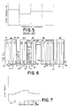
- Figure 6 shows a modified furnace 30, having a heating zone 32, a soaking zone 34, and a cooling region which includes a primary cooling zone 36, an overageing zone 38, and a final cooling zone 40.
- the strip 42 passes around an internal roll 44 which lies between the heating zone 32 and the soaking zone 34, thence around rollers 1, 2, 3, 4 and 5 within the soaking zone 34, thence around a further roller 46 between the soaking zone 34 and the primary cooling zone 36.
- strip elongation taking place within the soaking zone 34 is controlled by adjusting the speeds of rotation of the rolls 44 and 46. More particularly, this is done by controlling the amount by which the peripheral speed of the downstream roll 46 exceeds the peripheral speed of the upstream roll 44.
- the rolls 44 and 46 are equipped with precision resolvers 47, which monitor rotational speed and sense the elongation of the strip. In a steady state operation, the elongation of the strip 42 in the soak zone 34 is then easily calculated on the basis of the difference in rotational rates between the rolls 44 and 46, and the size of the rolls.
- the strip in the heating zone of the furnace may be controlled in the normal way, based on load cells feeding back to individual roll speeds in order to achieve the tapered tension.
- load cell regulation is dispensed within the soak zone 34 where the strip softens and becomes easily deformable.
- soak zone roll drive motors must be powerful enough to do the work of plastic elongation required in each pass. This is opposite the requirements for roll motors used in tension control schemes where the bridles do the work of elongation and roll drives operate at low power so as not to disturb tension uniformity in the soak zone.
- a consequence of the elongation control system provided herein could be a non-uniform, stepped, tension profile through the soak zone, allowing the strip to be a higher or lower tension in some passes than in others, or to cause the strip to increment to tensions different from the soak zone entry or exit tensions.
- An example is shown in Figure 7, and also in Figure 4.
- Figure 6 shows two resolvers 50 which monitor the speeds of the driven rolls 44 and 46 by making measurements on the freely rotating non-driven rolls 1 and 5 respectively, which are adjacent to the driven rolls.
- the freely-rotating rolls 1 and 5 are directly adjacent their corresponding driven rolls 44 and 46, there may be some additional elongation of the strip between each driven roll 44, 46 and its respective freely rotating rolls 1 or 5.
- the strip distance over which the elongation is taken to occur would be the distance between the freely rotating rolls 1 and 5, and not the distance between the rolls 44 and 46.
- the advantage of this arrangement is that it allows the avoidance of what is called the "slip angle" between a driven roll and a moving strip in contact with the driven roll. By resolving a non-driven roller (rollers 1 and 5) one obtains 100% accuracy of speed. There is thus no dead-band which, if present, could contribute a 0.1% error.
- soaking zone 14 which is defined by points 60 and 62, entrance shoulder 64 which is defined by point 66 and point 60, and exit shoulder 68 which is defined by point 62 and point 70.
- the strip in entrance shoulder 64 is in the final heating section of heating zone 12 and is probably plastic.
- the strip in soaking zone 14 is all plastic, and the strip in exit shoulder 68 is partly plastic.
- a strip width gauge includes a gauge head with two vertical beam laser seekers, two electro- servo laser beam positioners, remote push-button operator's control, remote computer and digital display, and optional printer.
- a strip width gauge 72 is mounted adjacent to and downstream of first roller 44, and another strip width gauge 74 is mounted upstream and adjacent to second roller 46.
- Gauges 72 and 74 measures the width of the strip, and the differences in width of the strip between first roller 44 and second roller 46 it is possible to calculate the elongation of the strip between first and second rollers 44, 46, using Poisson's Ratio for the strip material.
- a strip width gauge 72a is mounted at the entrance to gas-jet cooling zone 15 and a strip width gauge 74a is mounted at the exit of gas-jet cooling zone 15.
- a strip width gauge 72b is mounted at the entrance of the furnace 30 and a strip width gauge 74b is mounted at the exit end of furnace 30.
- a strip width gauge 72c ( Figure 6) is mounted at the entrance shoulder point 66, and a strip width gauge 74c is mounted at exit point 70 of shoulder 68.
- the tension in entrance zone 64 ( Figure 2) is decreased below the desired tension 82 in soaking zone 34 ( Figure 4) at the entrance shoulder zone of the soaking zone in order to minimize the elongation of the strip in the entrance shoulder zone 64.
- rollers including rollers 84-86 ( Figure 6) in the primary cooling zone 36 first reduce the tension in the strip in the exit shoulder 68 and then incrementally raise the tension to the tension desired when the strip leaves the overageing zone.
- the rolls are provided with sufficient power and individual control for increasing or decreasing tension on the strip by using all of the rolls or any combination of them.
Description
control means for adjusting the rotational speed of one of said driven rolls with respect to the other in response to the sensed elongation, thus controlling said elongation.
Claims (10)
- A method of annealing strip under tension in at least a portion (34) of a continuous annealing furnace (30) or the like, in which the strip is passed around a first driven roll (44) upstream of said portion (34) of the furnace thence through said portion (34) of the furnace, thence around a second driven roll (46) downstream of said portion (34) of the furnace, the strip (42) undergoing frictional contact with both rolls (44 and 46),
characterised by sensing the elongation of the strip (42) by measuring the strip width (72, 74) or by measuring the speeds of rolls in contact with the strip (1, 5 or 44, 46), and controlling strip elongation by adjusting the amount by which the peripheral speed of the second roll (46) exceeds the peripheral speed of the first roll (44) in response to the sensed elongation. - The method claimed in claim 1, in which said portion (34) of the furnace contains additional rolls (2,3,4,5) over which the strip is frictionally entrained, at least one of the said additional rolls being a driven roll, and in which the peripheral speed of said last-mentioned driven additional roll is controlled in order to further adjust strip elongation within said portion.
- The method claimed in claim 1 or 2, in which the elongation of the strip is measured by determining the peripheral speeds of the driven rolls by making measurements directly on said driven rolls (44,46).
- The method claimed in any of claims 1 to 3, in which the elongation of the strip is measured by determining the peripheral speeds of the driven rolls by making measurements on freely rotating, non-driven rolls (1,5) adjacent to the said driven rolls (44,46).
- The method claimed in any of claims 1 to 4, in which said sensing of the elongation of the strip is accomplished by measuring the difference in width of the strip before and after elongation.
- The method claimed in any preceding claim, in which said strip is under tension, and the tension of the strip is decreased as it approaches said portion of the furnace from the high level of tension required for strip tracking to a lower tension adapted for controlling the elongation of the strip in said portion without damaging the strip.
- A continuous strip annealing furnace (30) containing a portion (34) in which it is desired to anneal the strip (42) under tension, the furnace having:characterised by sensing means (47) for sensing the elongation of the strip by measuring the strip width (72, 74) or by measuring the speeds of rolls (1, 5 or 44, 46) in contact with the strip, anda first driven roll (44) adjacent the upstream end of said portion (34) and a second driven roll (46) adjacent the downstream end of said portion, the rolls (44,46) being such as to achieve frictional contact with the strip when the latter is entrained thereover, anddriving means for driving both said rolls such that the peripheral speed of the second roll (46) is greater than the peripheral speed of the first roll (44), thereby applying tension to the strip,
control means for adjusting the rotational speed of one of said driven rolls (44,46) with respect to the other in response to the sensed elongation, thus controlling said elongation. - The furnace claimed in claim 7, in which the furnace has an upstream end and a downstream end, and in which the furnace includes, in order from the upstream end to the downstream end, a heating zone (32), a soaking zone (34), a gas jet cooling zone (15), a primary cooling zone (36), an overageing zone (38) and a final cooling zone (40), and in which said portion of the furnace is the soaking zone (34) or the gas jet cooling zone (15).
- The furnace claimed in claim 7 or 8, in which both driven rolls are located within said portion of the furnace.
- The furnace claimed in any of claims 7 to 9, in which said portion (34) of the furnace contains additional rolls (2,3,4,5) over which the strip is frictionally entrained, at least one of the said additional rolls being a driven roll, and in which the furnace includes means for controlling the peripheral speed of said last-mentioned driven additional roll in order to further adjust strip elongation within said portion.
Applications Claiming Priority (2)
| Application Number | Priority Date | Filing Date | Title |
|---|---|---|---|
| US615900 | 1990-11-20 | ||
| US07/615,900 US5174835A (en) | 1989-11-22 | 1990-11-20 | Method of strip elongation control in continuous annealing furnaces |
Publications (3)
| Publication Number | Publication Date |
|---|---|
| EP0487274A2 EP0487274A2 (en) | 1992-05-27 |
| EP0487274A3 EP0487274A3 (en) | 1993-03-24 |
| EP0487274B1 true EP0487274B1 (en) | 1998-06-10 |
Family
ID=24467246
Family Applications (1)
| Application Number | Title | Priority Date | Filing Date |
|---|---|---|---|
| EP91310599A Expired - Lifetime EP0487274B1 (en) | 1990-11-20 | 1991-11-18 | Strip elongation control in continuous annealing furnaces |
Country Status (5)
| Country | Link |
|---|---|
| US (1) | US5174835A (en) |
| EP (1) | EP0487274B1 (en) |
| JP (1) | JPH0517829A (en) |
| AU (2) | AU646371B2 (en) |
| DE (1) | DE69129575T2 (en) |
Families Citing this family (4)
| Publication number | Priority date | Publication date | Assignee | Title |
|---|---|---|---|---|
| EP0675207B1 (en) * | 1994-03-02 | 1999-10-27 | Nippon Steel Corporation | Continuous annealing apparatus of steel strip and tension control system for the same |
| JP2013124415A (en) * | 2011-12-16 | 2013-06-24 | Ihi Corp | Device and method for heat treatment |
| JP7258619B2 (en) * | 2018-03-26 | 2023-04-17 | 株式会社神戸製鋼所 | Steel plate continuous annealing equipment and method for manufacturing annealed steel plate |
| CN113277719B (en) * | 2021-04-30 | 2022-08-30 | 彩虹(合肥)液晶玻璃有限公司 | Plate glass plate height control device |
Family Cites Families (8)
| Publication number | Priority date | Publication date | Assignee | Title |
|---|---|---|---|---|
| US2333282A (en) * | 1938-12-16 | 1943-11-02 | Acme Steel Co | Method of and apparatus for straightening strip steel |
| FR2313457A1 (en) * | 1975-06-06 | 1976-12-31 | Trefimetaux | METHOD AND APPARATUS FOR THE CONTINUOUS MEASUREMENT OF THE ANNUAL LEVEL ON WIRE OR TAPE |
| JPS607693B2 (en) * | 1979-10-31 | 1985-02-26 | 川崎製鉄株式会社 | Continuous annealing method for steel strip |
| JPS5943979B2 (en) * | 1979-10-31 | 1984-10-25 | 川崎製鉄株式会社 | Furnace tension control method |
| JPS5942733B2 (en) * | 1979-10-31 | 1984-10-17 | 川崎製鉄株式会社 | Steel strip continuous annealing equipment |
| JPS6033171B2 (en) * | 1980-06-19 | 1985-08-01 | 三菱電機株式会社 | Method for controlling the tension in the strip furnace |
| JPS61179819A (en) * | 1985-02-04 | 1986-08-12 | Nippon Steel Corp | Cooling method of metallic strip |
| US4913748A (en) * | 1988-07-05 | 1990-04-03 | Sellitto Thomas A | Method and apparatus for continuous annealing |
-
1990
- 1990-11-20 US US07/615,900 patent/US5174835A/en not_active Expired - Fee Related
-
1991
- 1991-11-18 EP EP91310599A patent/EP0487274B1/en not_active Expired - Lifetime
- 1991-11-18 DE DE69129575T patent/DE69129575T2/en not_active Expired - Fee Related
- 1991-11-18 JP JP3330071A patent/JPH0517829A/en not_active Ceased
- 1991-11-20 AU AU88021/91A patent/AU646371B2/en not_active Ceased
-
1994
- 1994-03-29 AU AU59173/94A patent/AU657650B2/en not_active Ceased
Also Published As
| Publication number | Publication date |
|---|---|
| DE69129575D1 (en) | 1998-07-16 |
| DE69129575T2 (en) | 1999-05-06 |
| AU8802191A (en) | 1992-05-21 |
| EP0487274A2 (en) | 1992-05-27 |
| JPH0517829A (en) | 1993-01-26 |
| US5174835A (en) | 1992-12-29 |
| AU657650B2 (en) | 1995-03-16 |
| AU5917394A (en) | 1994-06-02 |
| EP0487274A3 (en) | 1993-03-24 |
| AU646371B2 (en) | 1994-02-17 |
Similar Documents
| Publication | Publication Date | Title |
|---|---|---|
| JP3397877B2 (en) | Rolling method of rolled strip | |
| JPS6121729B2 (en) | ||
| JP3898927B2 (en) | Rolling mill stand | |
| US6336349B1 (en) | Method for the flexible rolling of a metallic strip | |
| KR101464093B1 (en) | Manufacturing device and manufacturing method for hot-rolled steel strip | |
| US6327883B1 (en) | Method of flattening metal strip | |
| US4261190A (en) | Flatness control in hot strip mill | |
| EP0024849B1 (en) | The operation of a multi-stand hot rolling mill | |
| EP0675207A1 (en) | Continuous annealing apparatus of steel strip and tension control system for the same | |
| KR20020093862A (en) | Method and device for reeling up in the proper position a hot-rolled strip in a reeling installation | |
| US5609053A (en) | Constant reduction multi-stand hot rolling mill set-up method | |
| EP0487274B1 (en) | Strip elongation control in continuous annealing furnaces | |
| JP2018058106A (en) | Continuous casting equipment and method for controlling plate crown | |
| US5230857A (en) | Strip elongation control in continuous annealing furnaces | |
| US5517842A (en) | Roll and strip cooling system for rolling mills | |
| CA2030453C (en) | Strip elongation control in continuous annealing furnaces | |
| JP3596460B2 (en) | Heat treatment method for thick steel plate and heat treatment equipment | |
| US6336350B1 (en) | Method for the flexible rolling of a metallic strip | |
| JPH1071415A (en) | Method for cooling shape beam | |
| AU2004283164A1 (en) | Control of hot rolled product cross section under localized temperature disturbances | |
| JPH01233005A (en) | Method for controlling plate width in hot rolling of thin cast billet | |
| JP2909543B2 (en) | Rolled material shape control method | |
| KR100328930B1 (en) | The hot rolling method for controlling the thickness and in the top end of strip | |
| JP2867857B2 (en) | Continuous annealing furnace with steel strip temperature controller | |
| JP3282714B2 (en) | Cooling method for hot steel sheet |
Legal Events
| Date | Code | Title | Description |
|---|---|---|---|
| PUAI | Public reference made under article 153(3) epc to a published international application that has entered the european phase |
Free format text: ORIGINAL CODE: 0009012 |
|
| AK | Designated contracting states |
Kind code of ref document: A2 Designated state(s): BE DE ES FR GB IT SE |
|
| PUAL | Search report despatched |
Free format text: ORIGINAL CODE: 0009013 |
|
| AK | Designated contracting states |
Kind code of ref document: A3 Designated state(s): BE DE ES FR GB IT SE |
|
| 17P | Request for examination filed |
Effective date: 19930520 |
|
| 17Q | First examination report despatched |
Effective date: 19941213 |
|
| GRAG | Despatch of communication of intention to grant |
Free format text: ORIGINAL CODE: EPIDOS AGRA |
|
| GRAG | Despatch of communication of intention to grant |
Free format text: ORIGINAL CODE: EPIDOS AGRA |
|
| GRAH | Despatch of communication of intention to grant a patent |
Free format text: ORIGINAL CODE: EPIDOS IGRA |
|
| GRAH | Despatch of communication of intention to grant a patent |
Free format text: ORIGINAL CODE: EPIDOS IGRA |
|
| GRAA | (expected) grant |
Free format text: ORIGINAL CODE: 0009210 |
|
| AK | Designated contracting states |
Kind code of ref document: B1 Designated state(s): BE DE ES FR GB IT SE |
|
| PG25 | Lapsed in a contracting state [announced via postgrant information from national office to epo] |
Ref country code: IT Free format text: LAPSE BECAUSE OF FAILURE TO SUBMIT A TRANSLATION OF THE DESCRIPTION OR TO PAY THE FEE WITHIN THE PRE;WARNING: LAPSES OF ITALIAN PATENTS WITH EFFECTIVE DATE BEFORE 2007 MAY HAVE OCCURRED AT ANY TIME BEFORE 2007. THE CORRECT EFFECTIVE DATE MAY BE DIFFERENT FROM THE ONE RECORDED.SCRIBED TIME-LIMIT Effective date: 19980610 Ref country code: ES Free format text: THE PATENT HAS BEEN ANNULLED BY A DECISION OF A NATIONAL AUTHORITY Effective date: 19980610 |
|
| REF | Corresponds to: |
Ref document number: 69129575 Country of ref document: DE Date of ref document: 19980716 |
|
| PG25 | Lapsed in a contracting state [announced via postgrant information from national office to epo] |
Ref country code: SE Free format text: LAPSE BECAUSE OF FAILURE TO SUBMIT A TRANSLATION OF THE DESCRIPTION OR TO PAY THE FEE WITHIN THE PRESCRIBED TIME-LIMIT Effective date: 19980910 |
|
| RAP2 | Party data changed (patent owner data changed or rights of a patent transferred) |
Owner name: SELAS CORPORATION OF AMERICA |
|
| ET | Fr: translation filed | ||
| PLBQ | Unpublished change to opponent data |
Free format text: ORIGINAL CODE: EPIDOS OPPO |
|
| PLBI | Opposition filed |
Free format text: ORIGINAL CODE: 0009260 |
|
| PLBF | Reply of patent proprietor to notice(s) of opposition |
Free format text: ORIGINAL CODE: EPIDOS OBSO |
|
| 26 | Opposition filed |
Opponent name: HOOGOVENS STAAL BV Effective date: 19990310 |
|
| PLBF | Reply of patent proprietor to notice(s) of opposition |
Free format text: ORIGINAL CODE: EPIDOS OBSO |
|
| PLBF | Reply of patent proprietor to notice(s) of opposition |
Free format text: ORIGINAL CODE: EPIDOS OBSO |
|
| PLBF | Reply of patent proprietor to notice(s) of opposition |
Free format text: ORIGINAL CODE: EPIDOS OBSO |
|
| PLBQ | Unpublished change to opponent data |
Free format text: ORIGINAL CODE: EPIDOS OPPO |
|
| PLAB | Opposition data, opponent's data or that of the opponent's representative modified |
Free format text: ORIGINAL CODE: 0009299OPPO |
|
| R26 | Opposition filed (corrected) |
Opponent name: HOOGOVENS STAAL BV Effective date: 19990310 |
|
| PLBO | Opposition rejected |
Free format text: ORIGINAL CODE: EPIDOS REJO |
|
| PLBN | Opposition rejected |
Free format text: ORIGINAL CODE: 0009273 |
|
| STAA | Information on the status of an ep patent application or granted ep patent |
Free format text: STATUS: OPPOSITION REJECTED |
|
| 27O | Opposition rejected |
Effective date: 20010217 |
|
| REG | Reference to a national code |
Ref country code: GB Ref legal event code: IF02 |
|
| PGFP | Annual fee paid to national office [announced via postgrant information from national office to epo] |
Ref country code: GB Payment date: 20021113 Year of fee payment: 12 |
|
| PGFP | Annual fee paid to national office [announced via postgrant information from national office to epo] |
Ref country code: DE Payment date: 20021121 Year of fee payment: 12 |
|
| PGFP | Annual fee paid to national office [announced via postgrant information from national office to epo] |
Ref country code: FR Payment date: 20031110 Year of fee payment: 13 |
|
| PG25 | Lapsed in a contracting state [announced via postgrant information from national office to epo] |
Ref country code: GB Free format text: LAPSE BECAUSE OF NON-PAYMENT OF DUE FEES Effective date: 20031118 |
|
| PGFP | Annual fee paid to national office [announced via postgrant information from national office to epo] |
Ref country code: BE Payment date: 20040121 Year of fee payment: 13 |
|
| PG25 | Lapsed in a contracting state [announced via postgrant information from national office to epo] |
Ref country code: DE Free format text: LAPSE BECAUSE OF NON-PAYMENT OF DUE FEES Effective date: 20040602 |
|
| GBPC | Gb: european patent ceased through non-payment of renewal fee |
Effective date: 20031118 |
|
| PG25 | Lapsed in a contracting state [announced via postgrant information from national office to epo] |
Ref country code: BE Free format text: LAPSE BECAUSE OF NON-PAYMENT OF DUE FEES Effective date: 20041130 |
|
| BERE | Be: lapsed |
Owner name: *SELAS CORP. OF AMERICA Effective date: 20041130 |
|
| PG25 | Lapsed in a contracting state [announced via postgrant information from national office to epo] |
Ref country code: FR Free format text: LAPSE BECAUSE OF NON-PAYMENT OF DUE FEES Effective date: 20050729 |
|
| REG | Reference to a national code |
Ref country code: FR Ref legal event code: ST |
|
| BERE | Be: lapsed |
Owner name: *SELAS CORP. OF AMERICA Effective date: 20041130 |