EP0486952A2 - Method for heating and bending a glass sheet - Google Patents
Method for heating and bending a glass sheet Download PDFInfo
- Publication number
- EP0486952A2 EP0486952A2 EP91119477A EP91119477A EP0486952A2 EP 0486952 A2 EP0486952 A2 EP 0486952A2 EP 91119477 A EP91119477 A EP 91119477A EP 91119477 A EP91119477 A EP 91119477A EP 0486952 A2 EP0486952 A2 EP 0486952A2
- Authority
- EP
- European Patent Office
- Prior art keywords
- resistance elements
- heating
- resistance
- resistances
- successive
- Prior art date
- Legal status (The legal status is an assumption and is not a legal conclusion. Google has not performed a legal analysis and makes no representation as to the accuracy of the status listed.)
- Granted
Links
- 238000005452 bending Methods 0.000 title claims abstract description 34
- 238000010438 heat treatment Methods 0.000 title claims abstract description 29
- 239000011521 glass Substances 0.000 title claims abstract description 28
- 238000000034 method Methods 0.000 title 1
- 230000007246 mechanism Effects 0.000 claims abstract description 8
- 238000003491 array Methods 0.000 description 5
- 238000001816 cooling Methods 0.000 description 1
- 238000010586 diagram Methods 0.000 description 1
- 238000005259 measurement Methods 0.000 description 1
Images


Classifications
-
- C—CHEMISTRY; METALLURGY
- C03—GLASS; MINERAL OR SLAG WOOL
- C03B—MANUFACTURE, SHAPING, OR SUPPLEMENTARY PROCESSES
- C03B29/00—Reheating glass products for softening or fusing their surfaces; Fire-polishing; Fusing of margins
- C03B29/04—Reheating glass products for softening or fusing their surfaces; Fire-polishing; Fusing of margins in a continuous way
- C03B29/06—Reheating glass products for softening or fusing their surfaces; Fire-polishing; Fusing of margins in a continuous way with horizontal displacement of the products
- C03B29/08—Glass sheets
-
- C—CHEMISTRY; METALLURGY
- C03—GLASS; MINERAL OR SLAG WOOL
- C03B—MANUFACTURE, SHAPING, OR SUPPLEMENTARY PROCESSES
- C03B23/00—Re-forming shaped glass
- C03B23/02—Re-forming glass sheets
- C03B23/023—Re-forming glass sheets by bending
- C03B23/0235—Re-forming glass sheets by bending involving applying local or additional heating, cooling or insulating means
-
- Y—GENERAL TAGGING OF NEW TECHNOLOGICAL DEVELOPMENTS; GENERAL TAGGING OF CROSS-SECTIONAL TECHNOLOGIES SPANNING OVER SEVERAL SECTIONS OF THE IPC; TECHNICAL SUBJECTS COVERED BY FORMER USPC CROSS-REFERENCE ART COLLECTIONS [XRACs] AND DIGESTS
- Y10—TECHNICAL SUBJECTS COVERED BY FORMER USPC
- Y10S—TECHNICAL SUBJECTS COVERED BY FORMER USPC CROSS-REFERENCE ART COLLECTIONS [XRACs] AND DIGESTS
- Y10S65/00—Glass manufacturing
- Y10S65/04—Electric heat
-
- Y—GENERAL TAGGING OF NEW TECHNOLOGICAL DEVELOPMENTS; GENERAL TAGGING OF CROSS-SECTIONAL TECHNOLOGIES SPANNING OVER SEVERAL SECTIONS OF THE IPC; TECHNICAL SUBJECTS COVERED BY FORMER USPC CROSS-REFERENCE ART COLLECTIONS [XRACs] AND DIGESTS
- Y10—TECHNICAL SUBJECTS COVERED BY FORMER USPC
- Y10S—TECHNICAL SUBJECTS COVERED BY FORMER USPC CROSS-REFERENCE ART COLLECTIONS [XRACs] AND DIGESTS
- Y10S65/00—Glass manufacturing
- Y10S65/13—Computer control
Definitions
- the present invention relates to a heating apparatus for a glass-sheet bending station, said apparatus comprising an array of elongated heating resistance elements, positioned side by side to develop a resistance field covering the area of a glass sheet to be bent, as well as a control mechanism for switching the resistance elements on and off.
- An object of the invention is to resolve the above problem by a novel arrangement and control of resistance elements in a manner that the heating pattern or the local focusing areas of heating can be controlled as desired in terms of their surface area, configuration and direction without maneuvering the resistances.
- All figures illustrate individual resistance elements 3 located on the left-hand side of the centre line 6 of a resistance element field.
- the number of resistance elements on one half-field is 3 x 20, i.e. 60 elements.
- the longitudinal direction of resistance elements 3 there are three separate resistance elements that can be independently switched on and off. These build up three successive resistance element fields, whose individual resistance elements 3 can be switched on at such a stagger that the resistances switched on in successive fields provide a heating line having a direction different from that of resistance elements 3.
- the direction of a heating line i.e. the degree of stagger of resistance elements, can be programmably controlled by employing the staggering of one or more adjacent resistances in successive fields.
- the resistance element field is typically located on the ceiling of a bending station and a glass sheet 4 to be bent is brought underneath the resistance field supported on a ring mould.
- the bending mould may also comprise a whole-surface mould or a combination of a ring mould and a partial-surface mould.
- Switching said resistance elements 3 on and off is effected by means of a control mechanism, comprising a PC computer 1 and a block 2 which includes a switch or a contactor in a power supply circuit leading to each resistance 3 as well as logic circuits, controlling the switches or contactors and reading the ON/OFF states of individual resistances 3 and informing the process-controlling computer 1 of any given switching pattern of the resistance field.
- a control mechanism comprising a PC computer 1 and a block 2 which includes a switch or a contactor in a power supply circuit leading to each resistance 3 as well as logic circuits, controlling the switches or contactors and reading the ON/OFF states of individual resistances 3 and informing the process-controlling computer 1 of any given switching pattern of the resistance field.
- the finished programs are recorded in the hard-disc memory of computer 1 for reading them therefrom for operation, if necessary.
- the programs can be corrected if necessary either by means of a graphical set-up program or by re-effecting the bending under a manual control.
- Such grouping or arraying lines include:
- each type of glass to be bent is provided with its own resistance-control program which, on the basis of a temperature measured at the bending point, switches on, or more correctly, neglects to switch on a certain number of resistances, the heating lines formed thereby being in the right place and at a suitable stagger for this particular type of glass.
Landscapes
- Chemical & Material Sciences (AREA)
- Engineering & Computer Science (AREA)
- Materials Engineering (AREA)
- Organic Chemistry (AREA)
- Re-Forming, After-Treatment, Cutting And Transporting Of Glass Products (AREA)
- Control Of Resistance Heating (AREA)
Abstract
Description
- The present invention relates to a heating apparatus for a glass-sheet bending station, said apparatus comprising an array of elongated heating resistance elements, positioned side by side to develop a resistance field covering the area of a glass sheet to be bent, as well as a control mechanism for switching the resistance elements on and off.
- The Applicant's Patent publication US 4 497 645 discloses a bending furnace, including a bending station in which the present invention can be applied. However, the invention is applicable in all types of glass-sheet bending stations in which a glass sheet is heated by means of electrical resistance elements close to a softening temperature at which a glass sheet can be bent. There can also be more than one bending station, e.g. two or three in succession. In this case, the bending of a glass sheet is effected sequentially in successive bending stations.
- When bending e.g. automotive windshields or backlights, it is necessary to localize or focus the heating effect on various sections of the glass in a manner that the glass sheet will be heated more in the areas of vigorous bending lines than in those areas which only require slight bending. Focusing the heat so as to achieve a controlled bending is problematic even in terms of just a single type of glass sheet to be bent. The situation will be particularly problematic when the locations and directions of bending lines also change along with the variations of types of glass sheets to be bent. Efforts have been made to resolve the problem by using maneuvarable and re-directable resistance elements (Patent publications EP 335 749 and US 4 726 832). However, mountting the maneuvering mechanisms in the hot interior of a bending station is a very invonvenient and expensive solution to carry out.
- An object of the invention is to resolve the above problem by a novel arrangement and control of resistance elements in a manner that the heating pattern or the local focusing areas of heating can be controlled as desired in terms of their surface area, configuration and direction without maneuvering the resistances.
- This object is achieved by means of the invention on the basis of the characterizing features set forth in the annexed
claim 1. - The invention will now be described in more detail with reference made to the accompanying drawings, in which
- fig. 1
- shows a block diagram of the main components and operation control for an apparatus of the invention.
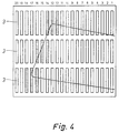
- Figs. 2 - 5
- illustrate various selections for switched-on resistance patterns with a varying surface are, number and direction (stagger) for individual heating lines.
- All figures illustrate
individual resistance elements 3 located on the left-hand side of thecentre line 6 of a resistance element field. In the present cases, the number of resistance elements on one half-field is 3 x 20, i.e. 60 elements. In the longitudinal direction ofresistance elements 3 there are three separate resistance elements that can be independently switched on and off. These build up three successive resistance element fields, whoseindividual resistance elements 3 can be switched on at such a stagger that the resistances switched on in successive fields provide a heating line having a direction different from that ofresistance elements 3. The direction of a heating line, i.e. the degree of stagger of resistance elements, can be programmably controlled by employing the staggering of one or more adjacent resistances in successive fields. In addition to this possibility, it is naturally possible to use other types of switching configurations for resistances; e.g. all resistances can be switched on; resistances of the top and bottom fields can be switched on and the mid-field resistances off or vice versa; and solely the top or bottom field resistances are switched on and the rest off. The various switching configurations or patterns of resistances can be used at various stages of a heating and bending cycle. However, towards the final stage of bending, as a glass sheet begins to bend, it is particularly important that the heating be focused on the bending lines. On the other hand, in order to develop an edge stress in a glass sheet, it is necessary to apply a uniform heating effect to the edges of a bent glass sheet prior to the rapid cooling thereof. The staggering of resistance elements according to the invention also facilitates heating the edge of glass sheets of varying sizes and shapes for developing an edge stress. - The resistance element field is typically located on the ceiling of a bending station and a
glass sheet 4 to be bent is brought underneath the resistance field supported on a ring mould. Naturally, the bending mould may also comprise a whole-surface mould or a combination of a ring mould and a partial-surface mould. - Switching said
resistance elements 3 on and off is effected by means of a control mechanism, comprising aPC computer 1 and ablock 2 which includes a switch or a contactor in a power supply circuit leading to eachresistance 3 as well as logic circuits, controlling the switches or contactors and reading the ON/OFF states ofindividual resistances 3 and informing the process-controllingcomputer 1 of any given switching pattern of the resistance field. - In a glass bending operation, the temperature of
glass 4 is being measured by means of one ormore pyrometers 5. During a bending operation, the measuring pyrometer will be selected to be the one closest to the major bending point of glass. The obtained measurement reading is supplied tocomputer 1, wherein it is used as a reference reading for controlling allresistance elements 3. As temperature rises, the only switched-onresistance elements 3 will be those whose respective column extends on the display ofcomputer 1 to above the corresponding temperature limit. Each successive field ofresistance elements 3 is provided with its own set of columns (not necessarily shown on the screen), the staggering of the invention being achieved by shifting the position of the tallest columns within the set of columns of successive resistance fields. - A bending program for a certain type of glass can be set up in two ways.
- 1. A first glass can be bent manually by using a
control panel 7, including aswitch 8 separately numbered for each resistance for switchingindividual resistance elements 3 on and off. The completed operations are stored as the bending is finished (teach-in). - 2. A bending program is set up by means of the CRT display and keyboard of
computer 1 by making use of a graphical parameters input program. - In both cases, the finished programs are recorded in the hard-disc memory of
computer 1 for reading them therefrom for operation, if necessary. The programs can be corrected if necessary either by means of a graphical set-up program or by re-effecting the bending under a manual control. - The control of resistance elements is accelerated and facilitated as they can be controlled as combined in various arrays. Such grouping or arraying lines include:
- 1. The left- or right-hand side of a bending station
- 2. The forward, middle or rear section of a bending station
- 3. The staggering of heating resistance elements in 0, 1, 2 or 3 steps
- 4. The switching of heating resistance elements in groups or arrays.
- These selections of groups or arrays are studied in more detail hereinafter.
- 1. Normally, when bending symmetrical glasses, a glass to be bent is placed in the middle of a bending station. In this case, the left- and right-hand
side heating resistances 3 of a bending station can be controlled simultaneously. Thus, the group selection "left and right" is set active. - 2. Depending on a type of glass to be bent, the group selection "forward, middle or rear section" can be used to provide more bending in the middle, top or bottom edge of a glass.
- 3. Fig. 2 shows an example, wherein the first array of resistance elements counted from the middle has a direct stepped selection, the fourth and fifth arrays of resistance elements have a direct stepped selection and a
fixed selection 2, the eighth, ninth and tenth arrays of resistance elements have a direct stepped selection and afixed selection 3 and the thirteenth array of resistance elements has astepped selection 1 and afixed selection 1. Fig. 3 shows astepped selection 0, fig. 4 astepped selection 2 and fig. 5 astepped selection 3. - 4. If
heating resistance elements 3 are to be switched on or off in the lateral direction of a furnace in larger groups, a group or array can be selected to include two or three adjacent heating resistance elements instead of just one element. - Thus, when applying the invention, each type of glass to be bent is provided with its own resistance-control program which, on the basis of a temperature measured at the bending point, switches on, or more correctly, neglects to switch on a certain number of resistances, the heating lines formed thereby being in the right place and at a suitable stagger for this particular type of glass.
Claims (6)
- Heating apparatus for a glass-sheet bending station, said apparatus comprising an array of elongated heating resistance elements (3), positioned side by side to develop a resistance field covering the area of a glass sheet (4) to be bent, as well as a control mechanism (1, 2) for switching resistance elements (3) on and off, characterized in that separate, independently controlled resistance elements (3) are positioned in resistance element fields successive in the longitudinal direction of said resistance elements and a control mechanism (1, 2) is adapted in accordance with a selected program to switch on resistances (3) of the successive resistance element fields in such a stagger that the resistances switched on in successive fields produce at least one heating line extending in a direction other than that of the resistance elements.
- An apparatus as set forth in claim 1, characterized in that the degree of stagger, i.e. the angle between said heating line and the longitudinal direction of resistances (3), is programmably adjustable by using in successive fields a shift of one or more adjacent resistances (3).
- An apparatus as set forth in claim 1 or 2, characterized in that adjacent heating lines have a different degree of stagger.
- An apparatus as set forth in any of claims 1 - 3, characterized in that adjacent heating lines include varying numbers of adjacent resistance elements (3).
- An apparatus as set forth in any of claims 1 - 4, characterized in that the heating lines on the left- and right-hand side of the centre line of resistance element fields are located symmetrically and extend symmetrically relative to said centre line.
- An apparatus as set forth in any of claims 1 - 5, characterized in that a pyrometer (5) is adapted to measure the temperature of glass (4) within the area of vigorous bending and the measured temperature serves in control mechanism (1, 2) as a reference reading for switching on a predetermined resistance pattern or for maintaining it switched-on depending on the measured temperature.
Applications Claiming Priority (3)
| Application Number | Priority Date | Filing Date | Title |
|---|---|---|---|
| FI905695 | 1990-11-19 | ||
| FI905695A FI86404C (en) | 1990-11-19 | 1990-11-19 | Heating device for bending section of glass panels |
| US07/795,735 US5470367A (en) | 1990-11-19 | 1991-11-21 | Heating apparatus for a glass-sheet bending station |
Publications (3)
| Publication Number | Publication Date |
|---|---|
| EP0486952A2 true EP0486952A2 (en) | 1992-05-27 |
| EP0486952A3 EP0486952A3 (en) | 1992-07-01 |
| EP0486952B1 EP0486952B1 (en) | 1995-10-18 |
Family
ID=26158852
Family Applications (1)
| Application Number | Title | Priority Date | Filing Date |
|---|---|---|---|
| EP91119477A Expired - Lifetime EP0486952B1 (en) | 1990-11-19 | 1991-11-14 | Method for heating and bending a glass sheet |
Country Status (3)
| Country | Link |
|---|---|
| US (1) | US5470367A (en) |
| EP (1) | EP0486952B1 (en) |
| JP (1) | JPH04275928A (en) |
Cited By (7)
| Publication number | Priority date | Publication date | Assignee | Title |
|---|---|---|---|---|
| EP0592862A1 (en) * | 1992-10-15 | 1994-04-20 | Tamglass Engineering Oy | Method and furnace for bending glass sheets |
| EP0659697A2 (en) * | 1993-12-23 | 1995-06-28 | Pilkington Glass Limited | Glass bending furnace |
| US5472469A (en) * | 1992-10-15 | 1995-12-05 | Tamglass Engineering Oy | Method of bending glass sheets |
| WO2001023310A1 (en) * | 1999-09-27 | 2001-04-05 | Asahi Glass Company, Limited | Bending apparatus for glass sheet and method of bending glass sheet |
| WO2006095006A1 (en) * | 2005-03-10 | 2006-09-14 | Glaverbel | Method and device for bending glass sheets |
| WO2006095007A1 (en) * | 2005-03-10 | 2006-09-14 | Glaverbel | Method of bending glass sheets |
| CN109673070A (en) * | 2018-12-31 | 2019-04-23 | 桂林电子科技大学 | A kind of programmable alternating temperature heating device of thermo parameters method |
Families Citing this family (11)
| Publication number | Priority date | Publication date | Assignee | Title |
|---|---|---|---|---|
| FR2658499B1 (en) * | 1990-02-21 | 1993-05-14 | Saint Gobain Vitrage Int | GLASS SHEET HEATING OVEN. |
| US6240746B1 (en) | 1997-04-04 | 2001-06-05 | Asahi Glass Company Ltd. | Glass plate bending method and apparatus |
| FI109199B (en) * | 2001-02-28 | 2002-06-14 | Tamglass Ltd Oy | Arrangement for bending glass plates |
| US6452135B1 (en) * | 2001-05-01 | 2002-09-17 | Johnson, Iii Joe P. | Heating unit with selectively energized heating modules |
| FI116726B (en) * | 2002-06-12 | 2006-02-15 | Tamglass Ltd Oy | Device for bending glass sheets |
| FI118178B (en) * | 2003-06-25 | 2007-08-15 | Tamglass Ltd Oy | Device for bending glass sheets |
| DE102006024484B3 (en) * | 2006-05-26 | 2007-07-19 | Saint-Gobain Sekurit Deutschland Gmbh & Co. Kg | Device for heating or bending glass panes has furnace section with controllable heating elements to form heating zones matching dimensions of glass panes passing through in transport moulds on transport carriage |
| DE102011050628A1 (en) | 2011-05-24 | 2012-11-29 | Get Glass Engineering Gmbh | Bending flat glass sheets by gravitational force, comprises arranging and fixing fastening devices on the glass sheet, guiding and tensioning the fastening devices on a support frame via connecting elements, and heating the support frame |
| FI127228B2 (en) * | 2013-05-23 | 2022-11-15 | Taifin Glass Machinery Oy | Method for heating glass sheets, and glass tempering furnace |
| DE102013105654A1 (en) | 2013-06-02 | 2014-12-04 | Interieur & Design Manufaktur Pfaltz GmbH | Method and apparatus for glass bending of flat glass with very tight bending radii according to the gravity bending method |
| JP2022163758A (en) * | 2021-04-15 | 2022-10-27 | 株式会社武内製作所 | Apparatus and method for molding glass into curved surface shape |
Citations (10)
| Publication number | Priority date | Publication date | Assignee | Title |
|---|---|---|---|---|
| US3744985A (en) * | 1971-06-08 | 1973-07-10 | Ppg Industries Inc | Method and apparatus for controlling temperature of conveyed glass sheets |
| EP0078135A1 (en) * | 1981-10-23 | 1983-05-04 | McMaster, Harold Ashley | Method of controlling the heating of sheet material in a conveyor furnace |
| US4528016A (en) * | 1983-09-12 | 1985-07-09 | Canfield Douglas M | Glass sheet treating furnace with a roller conveyor |
| EP0241356A1 (en) * | 1986-04-09 | 1987-10-14 | Saint-Gobain Vitrage International | Heating techniques for glass sheets |
| US4807144A (en) * | 1986-12-02 | 1989-02-21 | Glasstech International L.P. | Temperature control system for glass sheet furnace |
| EP0376509A1 (en) * | 1988-12-27 | 1990-07-04 | Ford Motor Company Limited | Method and apparatus for directed energy glass heating |
| US4952227A (en) * | 1989-05-22 | 1990-08-28 | Libbey-Owens-Ford Co. | Apparatus for processing glass |
| US4957532A (en) * | 1989-06-20 | 1990-09-18 | Casso-Solar Corporation | Glass-treating furnace with roller conveyor |
| EP0443948A1 (en) * | 1990-02-21 | 1991-08-28 | Saint-Gobain Vitrage International | Bending of glass-sheets by gravity on a bending mould |
| EP0443947A1 (en) * | 1990-02-21 | 1991-08-28 | Saint-Gobain Vitrage International | Furnace for reheating sheets of glass |
Family Cites Families (3)
| Publication number | Priority date | Publication date | Assignee | Title |
|---|---|---|---|---|
| US3001328A (en) * | 1958-07-25 | 1961-09-26 | Pittsburgh Plate Glass Co | Glass bending lehrs and conveyors therefor |
| US4601743A (en) * | 1983-09-12 | 1986-07-22 | Casso Solar Corporation | Glass furnace with heat sensing means |
| FR2621406B1 (en) * | 1987-10-02 | 1990-01-05 | Saint Gobain Vitrage | INDUSTRIAL ELECTRIC OVEN CONTROL |
-
1991
- 1991-11-14 EP EP91119477A patent/EP0486952B1/en not_active Expired - Lifetime
- 1991-11-19 JP JP3330013A patent/JPH04275928A/en active Pending
- 1991-11-21 US US07/795,735 patent/US5470367A/en not_active Expired - Lifetime
Patent Citations (10)
| Publication number | Priority date | Publication date | Assignee | Title |
|---|---|---|---|---|
| US3744985A (en) * | 1971-06-08 | 1973-07-10 | Ppg Industries Inc | Method and apparatus for controlling temperature of conveyed glass sheets |
| EP0078135A1 (en) * | 1981-10-23 | 1983-05-04 | McMaster, Harold Ashley | Method of controlling the heating of sheet material in a conveyor furnace |
| US4528016A (en) * | 1983-09-12 | 1985-07-09 | Canfield Douglas M | Glass sheet treating furnace with a roller conveyor |
| EP0241356A1 (en) * | 1986-04-09 | 1987-10-14 | Saint-Gobain Vitrage International | Heating techniques for glass sheets |
| US4807144A (en) * | 1986-12-02 | 1989-02-21 | Glasstech International L.P. | Temperature control system for glass sheet furnace |
| EP0376509A1 (en) * | 1988-12-27 | 1990-07-04 | Ford Motor Company Limited | Method and apparatus for directed energy glass heating |
| US4952227A (en) * | 1989-05-22 | 1990-08-28 | Libbey-Owens-Ford Co. | Apparatus for processing glass |
| US4957532A (en) * | 1989-06-20 | 1990-09-18 | Casso-Solar Corporation | Glass-treating furnace with roller conveyor |
| EP0443948A1 (en) * | 1990-02-21 | 1991-08-28 | Saint-Gobain Vitrage International | Bending of glass-sheets by gravity on a bending mould |
| EP0443947A1 (en) * | 1990-02-21 | 1991-08-28 | Saint-Gobain Vitrage International | Furnace for reheating sheets of glass |
Cited By (13)
| Publication number | Priority date | Publication date | Assignee | Title |
|---|---|---|---|---|
| EP0592862A1 (en) * | 1992-10-15 | 1994-04-20 | Tamglass Engineering Oy | Method and furnace for bending glass sheets |
| US5437704A (en) * | 1992-10-15 | 1995-08-01 | Tamglass Engineering Oy | Method and furnace for bending glass sheets |
| US5472469A (en) * | 1992-10-15 | 1995-12-05 | Tamglass Engineering Oy | Method of bending glass sheets |
| EP0659697A2 (en) * | 1993-12-23 | 1995-06-28 | Pilkington Glass Limited | Glass bending furnace |
| EP0659697A3 (en) * | 1993-12-23 | 1996-01-10 | Pilkington Glass Ltd | Glass bending furnace. |
| US5656052A (en) * | 1993-12-23 | 1997-08-12 | Pilkington Glass Limited | Apparatus for and method of heating and bending glass sheet |
| WO2001023310A1 (en) * | 1999-09-27 | 2001-04-05 | Asahi Glass Company, Limited | Bending apparatus for glass sheet and method of bending glass sheet |
| US7331198B1 (en) | 1999-09-27 | 2008-02-19 | Asahi Glass Company, Limited | Bending apparatus for a glass sheet |
| WO2006095006A1 (en) * | 2005-03-10 | 2006-09-14 | Glaverbel | Method and device for bending glass sheets |
| WO2006095007A1 (en) * | 2005-03-10 | 2006-09-14 | Glaverbel | Method of bending glass sheets |
| BE1016542A3 (en) * | 2005-03-10 | 2007-01-09 | Glaverbel | Method and device for bending glass sheets. |
| BE1016541A3 (en) * | 2005-03-10 | 2007-01-09 | Glaverbel | Method and device for bending glass sheets. |
| CN109673070A (en) * | 2018-12-31 | 2019-04-23 | 桂林电子科技大学 | A kind of programmable alternating temperature heating device of thermo parameters method |
Also Published As
| Publication number | Publication date |
|---|---|
| EP0486952B1 (en) | 1995-10-18 |
| US5470367A (en) | 1995-11-28 |
| EP0486952A3 (en) | 1992-07-01 |
| JPH04275928A (en) | 1992-10-01 |
Similar Documents
| Publication | Publication Date | Title |
|---|---|---|
| EP0486952A2 (en) | Method for heating and bending a glass sheet | |
| AU739552B2 (en) | Method and apparatus for the localization of heating in a tempering furnace for glass panels | |
| US4688180A (en) | Pattern-switching temperature control apparatus | |
| DE112008000413B4 (en) | Hob with a movable heating element | |
| DE4007680A1 (en) | Glass-ceramic cooking hob - has field of sensor-driven elements each a preset different power outputs | |
| EP0476693B1 (en) | Method and apparatus for bending a glass sheet | |
| CN103621177B (en) | Induction heating apparatus, induction heating equipment, induction heating method and heat treatment method | |
| EP0596263B1 (en) | Cooking oven | |
| DE10133135A1 (en) | Actuator for cooking devices | |
| AU780337B2 (en) | Apparatus for bending glass panels | |
| KR20060123085A (en) | Control for a cooking device and method for controlling a cooking device | |
| EP0568053A1 (en) | Method and apparatus for bending and tempering a glass sheet | |
| DE10033361A1 (en) | Matrix cooking unit has matrices of heating zones and sensor points for locating cooking vessels and measuring cooking temperatures | |
| DE19836174C2 (en) | Heater for heating thermoplastic sheets and method for adjusting the temperature of this heater | |
| KR101386907B1 (en) | Roller cooling oven | |
| FI86404C (en) | Heating device for bending section of glass panels | |
| CN112747603A (en) | Wire winding structure and thermal field temperature control method | |
| CN113578982B (en) | Slab induction heating adjustment method and induction heating system | |
| US2999338A (en) | Glass bending mould | |
| EP0388604B1 (en) | Electric baking oven | |
| JPH11199254A (en) | Heating temperature controller for glass plate bending device | |
| KR100467134B1 (en) | Control system for heating in glass bending oven | |
| US3510285A (en) | Fusing glass sheets by electric heat | |
| EP2133012B1 (en) | A cooking device with a hot plate and heating element | |
| EP0016329B1 (en) | Switching unit for stepwise selection of the switched-on time of the heating of an electrical apparatus |
Legal Events
| Date | Code | Title | Description |
|---|---|---|---|
| PUAI | Public reference made under article 153(3) epc to a published international application that has entered the european phase |
Free format text: ORIGINAL CODE: 0009012 |
|
| PUAL | Search report despatched |
Free format text: ORIGINAL CODE: 0009013 |
|
| AK | Designated contracting states |
Kind code of ref document: A2 Designated state(s): CH DE FR GB IT LI |
|
| AK | Designated contracting states |
Kind code of ref document: A3 Designated state(s): CH DE FR GB IT LI |
|
| 17P | Request for examination filed |
Effective date: 19921204 |
|
| RAP1 | Party data changed (applicant data changed or rights of an application transferred) |
Owner name: TAMGLASS ENGINEERING OY |
|
| 17Q | First examination report despatched |
Effective date: 19931208 |
|
| GRAA | (expected) grant |
Free format text: ORIGINAL CODE: 0009210 |
|
| AK | Designated contracting states |
Kind code of ref document: B1 Designated state(s): CH DE FR GB IT LI |
|
| ITF | It: translation for a ep patent filed | ||
| REF | Corresponds to: |
Ref document number: 69113953 Country of ref document: DE Date of ref document: 19951123 |
|
| PGFP | Annual fee paid to national office [announced via postgrant information from national office to epo] |
Ref country code: CH Payment date: 19951227 Year of fee payment: 5 |
|
| ET | Fr: translation filed | ||
| PLBE | No opposition filed within time limit |
Free format text: ORIGINAL CODE: 0009261 |
|
| STAA | Information on the status of an ep patent application or granted ep patent |
Free format text: STATUS: NO OPPOSITION FILED WITHIN TIME LIMIT |
|
| 26N | No opposition filed | ||
| PG25 | Lapsed in a contracting state [announced via postgrant information from national office to epo] |
Ref country code: CH Effective date: 19961130 Ref country code: LI Effective date: 19961130 |
|
| REG | Reference to a national code |
Ref country code: CH Ref legal event code: PL |
|
| REG | Reference to a national code |
Ref country code: GB Ref legal event code: IF02 |
|
| REG | Reference to a national code |
Ref country code: FR Ref legal event code: CD |
|
| PGFP | Annual fee paid to national office [announced via postgrant information from national office to epo] |
Ref country code: DE Payment date: 20071029 Year of fee payment: 17 |
|
| PGFP | Annual fee paid to national office [announced via postgrant information from national office to epo] |
Ref country code: IT Payment date: 20071023 Year of fee payment: 17 |
|
| PGFP | Annual fee paid to national office [announced via postgrant information from national office to epo] |
Ref country code: FR Payment date: 20071011 Year of fee payment: 17 Ref country code: GB Payment date: 20071018 Year of fee payment: 17 |
|
| GBPC | Gb: european patent ceased through non-payment of renewal fee |
Effective date: 20081114 |
|
| PG25 | Lapsed in a contracting state [announced via postgrant information from national office to epo] |
Ref country code: IT Free format text: LAPSE BECAUSE OF NON-PAYMENT OF DUE FEES Effective date: 20081114 |
|
| REG | Reference to a national code |
Ref country code: FR Ref legal event code: ST Effective date: 20090731 |
|
| PG25 | Lapsed in a contracting state [announced via postgrant information from national office to epo] |
Ref country code: DE Free format text: LAPSE BECAUSE OF NON-PAYMENT OF DUE FEES Effective date: 20090603 |
|
| PG25 | Lapsed in a contracting state [announced via postgrant information from national office to epo] |
Ref country code: GB Free format text: LAPSE BECAUSE OF NON-PAYMENT OF DUE FEES Effective date: 20081114 |
|
| PG25 | Lapsed in a contracting state [announced via postgrant information from national office to epo] |
Ref country code: FR Free format text: LAPSE BECAUSE OF NON-PAYMENT OF DUE FEES Effective date: 20081130 |