EP0486919A2 - Method and circuit for block synchronisation of redundantly encoded data - Google Patents
Method and circuit for block synchronisation of redundantly encoded data Download PDFInfo
- Publication number
- EP0486919A2 EP0486919A2 EP91119216A EP91119216A EP0486919A2 EP 0486919 A2 EP0486919 A2 EP 0486919A2 EP 91119216 A EP91119216 A EP 91119216A EP 91119216 A EP91119216 A EP 91119216A EP 0486919 A2 EP0486919 A2 EP 0486919A2
- Authority
- EP
- European Patent Office
- Prior art keywords
- characters
- block
- test
- received
- points
- Prior art date
- Legal status (The legal status is an assumption and is not a legal conclusion. Google has not performed a legal analysis and makes no representation as to the accuracy of the status listed.)
- Withdrawn
Links
Images


Classifications
-
- H—ELECTRICITY
- H04—ELECTRIC COMMUNICATION TECHNIQUE
- H04L—TRANSMISSION OF DIGITAL INFORMATION, e.g. TELEGRAPHIC COMMUNICATION
- H04L7/00—Arrangements for synchronising receiver with transmitter
- H04L7/04—Speed or phase control by synchronisation signals
- H04L7/048—Speed or phase control by synchronisation signals using the properties of error detecting or error correcting codes, e.g. parity as synchronisation signal
Definitions
- the invention relates to a method for block synchronization of redundantly encoded data, wherein a data block has n characters, which are composed of k information characters at k fixed information points in the block and nk test characters at the remaining nk points, the test points, the nk test characters from the k Information characters are derived in accordance with a coding, the characters received at the k information points being separated from any block of n characters on the receiving side and nk test characters being generated in accordance with the coding on the transmission side, which are compared with the nk characters of the arbitrary block received at the testing points and a comparison value, which is a measure of the degree of correspondence between the nk test characters generated at the receiving end and the nk characters of the block received at the test locations, is generated.
- the invention also relates to a circuit arrangement for block synchronization of data encoded with redundancy, wherein a data block has n characters, which are composed of k information characters at k fixed information points in the block and nk test characters at the remaining nk locations, the test locations, the nk test characters from the k information characters are derived in accordance with a coding, an encoder being provided at the receiving end in which n-k test characters are generated from the k characters of any block of n characters received at the information points in accordance with the coding at the transmitting end, a comparator being provided which nk test mark with the an compares the nk characters of any block received to the test centers and generates a comparison value.
- Forward error correction techniques are used to reduce the likelihood of character errors when transmitting data over disturbed channels.
- the data are divided into blocks of k characters, transcoded into blocks (code words) of n characters (n> k) according to a suitable coding rule and then transmitted serially over the channel.
- the encryption is done with a systematic code, i.e. a block (code word) has k digits of message and n-k digits of redundant check characters.
- the coded messages must be recognized, corrected and decoded on the receiving side.
- the serially supplied data must be processed in blocks of n characters synchronized with the transmission side for error correction.
- frame identifier words are usually transmitted which mark the beginning of a data block at fixed intervals.
- a disadvantage of this method is that an increased channel capacity must be made available for the transmission of the synchronous word.
- a method for the synchronous transmission of frame-structured data is known from EP 100820-A2, the frame having a synchronization component and an error protection component in addition to the data component.
- the error protection component or the synchronization component is advantageously used twice, so that channel capacity can be saved.
- the error protection component can therefore be used at the receiving end for synchronization as well as for error correction.
- the process works on the principle of trial and error. It starts from any position of the Data blocks and shifts them by one position each time the number of characters derived from the k characters received at the information points and the nk characters received at the test points do not match in more than s places.
- This method has the disadvantage that the synchronization process can take a very long time, since even with error-free transmission an average of n: 2 and, in the worst case, n attempts are necessary to establish the synchronicity.
- the method according to the invention has good channel utilization, the synchronization capability being in no way restricted.
- the method according to the invention makes it possible to achieve synchronization after M block cycles.
- the synchronization time has been significantly reduced compared to previous methods.
- a high degree of reliability, even with high channel error rates, can be achieved with the method according to the invention. It can be used advantageously in all systems in which data is protected by so-called systematic error-detecting or error-correcting codes and the code words that are generated are transmitted serially.
- the block diagram of a transmitter is shown in Figure 1.
- the data sequence m d (t) to be processed is continuously divided into blocks of k characters in a serial-parallel converter S / P with the clock T d .
- the k-character data sequence and the p-character sequence of the parity characters are fed to a parallel-serial converter P / S.
- the characters are structured into blocks of a total of n characters.
- the information signs are located at any fixed information points and the test marks at any fixed test points in the block.
- the resulting data sequence m c (t) is transmitted serially over a transmission channel.
- the received data sequence r (t) superimposed by interference is fed to a receiver.
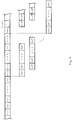
- a resulting block structure can be seen in FIG. 2.
- the data sequence m d (t) to be processed is initially shown above. It is divided into blocks of k characters (m i, 1 , m i, 2 , ..., m i, k ).
- a block clock interval T B corresponds to k character clock intervals T m of the data sequence m d (t) to be processed. From the k Information characters are formed from p parity characters (c i, 1 , c i, 2 , ...
- FIG. 4 A circuit arrangement for block synchronization on the receiving side is shown in FIG. The principle is based on the parallel - i.e. simultaneous - checking of all n possible block assignments.
- the received data signal r (t) runs through a chain of runtime elements with a delay of one character clock interval T C each.
- Each of the total of n signals is fed to a serial-parallel converter S / P1, S / P2, .., S / Pn, which continuously divides the input signal into blocks comprising n characters.
- the received data signal r (t) is shown in FIG. 4.
- test characters c i, 1 (j) c i, 2 (j) , .. c i, p (j) are generated from a block shifted by 1 character.
- the generated test characters are compared in a comparator K1, K2,... Kn with the last p characters of the block in question, which are at the test points of the block.
- the temporal last p characters are also shifted by one character in the different branches (FIG. 4).
- the comparators K1, K2, ..., Kn are each assigned the last p characters of the relevant block by the associated serial parallel converters S / P1, S / P2, ..., S / Pn and by the encoder E1, E2, ... , E3 fed the p test marks.
- This signal SY (j) is fed to one of the summers SUM1, SUM2, ..., SUMn, which sums up the p output signals of the comparators in question over the duration of M block clocks in each case.
- the n sum signals generated are then evaluated in a function block A for evaluating and determining an estimated value for the block clock T ⁇ b for the block clock synchronous with the transmission side.
- Threshold procedure Each of the n sum signals is compared with a suitably defined threshold value.
- the block assignment corresponding to this sum signal is selected as the one synchronous to the transmission side and the synchronization process is ended. If several sum signals fall below this threshold value at the same time, no clear decision can be made. In this case reset the n sum signals to the value 0 and repeat the described synchronization process.
- Minimum method From the n possible block assignments, the one that is synchronous to the transmission side is selected, which delivers the minimum sum signal as described above. If several minimum sum signals occur at the same time, all n sums must be reset to the value 0 and the described synchronization process must be repeated.
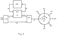
- FIG. 5 shows an arrangement with which a serial check of all n possible block assignments can be carried out during a block clock interval. Compared to the parallel processing of all possible n block assignments, the circuitry required for serial processing is considerably less. There is no need for a runtime chain, furthermore only an encoder ES and a comparator KS needed. This work in the drawing cycle T C.
- the received data r (t) are divided in a serial-parallel converter S / PS into blocks of n characters. With each character ri arriving at the serial-parallel converter S / PS, the block at the output of the serial-parallel converter S / PS is shifted by one character. The first k characters of the respective block are fed to the encoder ES, the state Z (j) of which is stored cyclically in a register ZR or loaded from this register into the encoder.
- the evaluation takes place, as has already been described for FIG. 3.
Abstract
Description
Die Erfindung betrifft ein Verfahren zur Blocksynchronisation redundanzhaltig encodierter Daten, wobei ein Datenblock n Zeichen aufweist, die sich aus k Informationszeichen an k festen Informationsstellen im Block und n-k Prüfzeichen an den restlichen n-k Stellen, den Prüfstellen, zusammensetzen, wobei die n-k Prüfzeichen aus den k Informationszeichen gemäß einer Codierung abgeleitet werden, wobei auf der Empfangsseite die an den k Informationsstellen empfangenen Zeichen von einem beliebigen Block mit n Zeichen abgetrennt werden und gemäß der sendeseitigen Codierung n-k Prüfzeichen erzeugt werden, die mit den an den Prüfstellen empfangenen n-k Zeichen des beliebigen Blocks verglichen werden und ein Vergleichswert, der ein Maß für den Grad der Übereinstimmung von den empfangsseitig erzeugten n-k Prüfzeichen und den an den Prüfstellen empfangenen n-k Zeichen des Blocks ist, erzeugt wird. Die Erfindung betrifft außerdem eine Schaltungsanordnung Zur Blocksynchronisation redundanzhaltig encodierter Daten, wobei ein Datenblock n Zeichen aufweist, die sich aus k Informationszeichen an k festen Informationsstellen im Block und n-k Prüfzeichen an den restlichen n-k Stellen, den Prüfstellen, zusammensetzen, wobei die n-k Prüfzeichen aus den k Informationszeichen gemäß einer Codierung abgeleitet werden, wobei empfangsseitig ein Encoder vorgesehen ist, in dem aus den an den Informationsstellen empfangenen k Zeichen eines beliebigen Blockes von n Zeichen gemäß der sendeseitigen Codierung n- k Prüfzeichen erzeugt werden, wobei ein Komparator vorgesehen ist, der die n-k Prüfzeichen mit den an den Prüfstellen empfangenen n-k Zeichen des beliebigen Blocks vergleicht und einen Vergleichswert erzeugt.The invention relates to a method for block synchronization of redundantly encoded data, wherein a data block has n characters, which are composed of k information characters at k fixed information points in the block and nk test characters at the remaining nk points, the test points, the nk test characters from the k Information characters are derived in accordance with a coding, the characters received at the k information points being separated from any block of n characters on the receiving side and nk test characters being generated in accordance with the coding on the transmission side, which are compared with the nk characters of the arbitrary block received at the testing points and a comparison value, which is a measure of the degree of correspondence between the nk test characters generated at the receiving end and the nk characters of the block received at the test locations, is generated. The invention also relates to a circuit arrangement for block synchronization of data encoded with redundancy, wherein a data block has n characters, which are composed of k information characters at k fixed information points in the block and nk test characters at the remaining nk locations, the test locations, the nk test characters from the k information characters are derived in accordance with a coding, an encoder being provided at the receiving end in which n-k test characters are generated from the k characters of any block of n characters received at the information points in accordance with the coding at the transmitting end, a comparator being provided which nk test mark with the an compares the nk characters of any block received to the test centers and generates a comparison value.
Ein gattungsgemäßes Verfahren und eine gattungsgemäße Anordnung sind aus Swoboda, J., Codierung zur Fehlerkorrektur und Fehlererkennung, München, Wien, 1973 bekannt.A generic method and a generic arrangement are known from Swoboda, J., Coding for Error Correction and Error Detection, Munich, Vienna, 1973.
Bei der Übertragung von Daten über gestörte Kanäle werden Vorwärtsfehlerkorrekturverfahren zur Minderung der Zeichenfehlerwahrscheinlichkeit verwendet. Auf der Sendeseite werden die Daten in Blöcke zu je k Zeichen unterteilt, nach einer geeigneten Codiervorschrift in Blöcke (Codeworte) zu je n Zeichen (n>k) umcodiert und anschließend seriell über den Kanal übertragen. Die Verschlüsselung erfolgt mit einem systematischen Code, d.h. ein Block (Codewort) weist k Stellen Nachricht und n-k Stellen redundante Prüfzeichen auf. Auf der Empfangsseite müssen die codierten Nachrichten erkannt, korrigiert und decodiert werden. Bei der Decodierung müssen zur Fehlerkorrektur die seriell angelieferten Daten synchron zur Sendeseite in Blöcke zu je n Zeichen verarbeitet werden.Forward error correction techniques are used to reduce the likelihood of character errors when transmitting data over disturbed channels. On the transmission side, the data are divided into blocks of k characters, transcoded into blocks (code words) of n characters (n> k) according to a suitable coding rule and then transmitted serially over the channel. The encryption is done with a systematic code, i.e. a block (code word) has k digits of message and n-k digits of redundant check characters. The coded messages must be recognized, corrected and decoded on the receiving side. When decoding, the serially supplied data must be processed in blocks of n characters synchronized with the transmission side for error correction.
Aus Swoboda, a.a.O., ist ein Korrekturverfahren, die "Korrektur durch Listenvergleich" bekannt, bei dem ein empfangener Block mit allen möglichen Codeworten verglichen wird und das Codewort, das dem empfangenen Block am ähnlichsten ist, als Ergebnis der Korrektur betrachtet wird. Dabei wird davon ausgegangen, daß die empfangenen Daten synchron zur Sendeseite in Blöcke unterteilt wurden.From Swoboda, op. Cit., A correction method, the "correction by list comparison" is known, in which a received block is compared with all possible code words and the code word that is most similar to the received block is considered as the result of the correction. It is assumed that the received data have been divided into blocks synchronously with the transmission side.
Zum Zweck der Synchronisation werden üblicherweise Rahmenkennungsworte übertragen, die in festen Abständen den Beginn eines Datenblocks markieren. Nachteilig an diesem Verfahren ist, daß zur Übertragung des Synchronwortes eine erhöhte Kanalkanazität zur Verfügung gestellt werden muß.For the purpose of synchronization, frame identifier words are usually transmitted which mark the beginning of a data block at fixed intervals. A disadvantage of this method is that an increased channel capacity must be made available for the transmission of the synchronous word.
In der US-PS 359811 ist die Synchronisation mittels Paritätsbits bei Puls-Code-Systemen beschrieben, und es ist auch ein Blockschaltbild für ein selbstsynchronisierendes Decodersystem mit einem Paritätsbit pro Codewort zu entnehmen.In US Pat. No. 3,59811, synchronization by means of parity bits in pulse code systems is described, and a block diagram for a self-synchronizing decoder system with one parity bit per code word can also be found.
Aus der EP 100820-A2 ist ein Verfahren zur Synchronübertragung rahmenstrukturierter Daten bekannt, wobei der Rahmen neben dem Datenanteil einen Synchronisationsanteil und zusätzlich einen Fehlerschutzanteil aufweist. Vorteilhafterweise wird der Fehlerschutzanteil oder der Synchronisationsanteil doppelt ausgenutzt, so daß Kanalkapazität eingespart werden kann. Der Fehlerschutzanteil kann also empfangsseitig sowohl zur Synchronisation als auch zur Fehlerkorrektur herangezogen werden. Das Verfahren arbeitet nach dem Prinzip von Versuch und Irrtum. Es geht zunächst von einer beliebigen Lage des Datenblocks aus und verschiebt diese um jeweils eine Stelle, sobald die Anzahl der aus den an den Informationsstellen empfangenen k Zeichen abgeleiteten Zeichen und der n-k an den Prüfstellen empfangenen Zeichen in mehr als s Stellen nicht miteinander übereinstimmen. Dieses Verfahren hat den Nachteil, daS der Synchronisationsvorgang unter Umständen sehr lange Zeit in Anspruch nimmt, da selbst bei fehlerfreier Übertragung im Mittel n:2 und im ungünstigsten Fall n Versuche bis zur Herstellung der Synchronität notwendig sind.A method for the synchronous transmission of frame-structured data is known from EP 100820-A2, the frame having a synchronization component and an error protection component in addition to the data component. The error protection component or the synchronization component is advantageously used twice, so that channel capacity can be saved. The error protection component can therefore be used at the receiving end for synchronization as well as for error correction. The process works on the principle of trial and error. It starts from any position of the Data blocks and shifts them by one position each time the number of characters derived from the k characters received at the information points and the nk characters received at the test points do not match in more than s places. This method has the disadvantage that the synchronization process can take a very long time, since even with error-free transmission an average of n: 2 and, in the worst case, n attempts are necessary to establish the synchronicity.
Es ist Aufgabe der Erfindung, ein Verfahren und eine Schaltungsanordnung anzugeben, die unter Beibehaltung der Synchronisationsmöglichkeit eine geringe Kanalkapazität benötigt und mit einer geringen Synchronistionszeit auskommt.It is an object of the invention to provide a method and a circuit arrangement which, while maintaining the possibility of synchronization, requires a small channel capacity and manages with a short synchronization time.
Die Lösung der Aufgabe erfolgt bezüglich des Verfahrens mit den im Patentanspruch 1 angegebenen Verfahrensschritten und bezüglich der Schaltungsanordnung mit den in den Patentansprüchen 4 und 5 angegebenen Mitteln. Vorteilhafte Weiterbildungen des Verfahrens sind in den Patentansprüchen 2 und 3 angegeben.The problem is solved with respect to the method with the method steps specified in
Das erfindungsgemäße Verfahren weist eine gute Kanalausnutzung auf, wobei die Synchronisationsfähigkeit in keiner Weise eingeschränkt wird. Zudem ist es mit dem erfindungsgemäßen Verfahren möglich, eine Synchronisation nach M Blocktakten zu erreichen. Die Synchronisationszeit ist gegenüber bisherigen Verfahren wesentlich verkürzt worden. Eine hohe Zuverlässigkeit auch bei hohen Kanalfehlerraten ist mit dem erfindungsgemäßen Verfahren erreichbar. Es kann in vorteilhafter Weise in allen Systemen angewendet werden, in denen Daten durch sogenannte systematische fehlererkennende oder fehlerkorrigierende Codes geschützt und die entstehenden Codeworte seriell übertragen werden.The method according to the invention has good channel utilization, the synchronization capability being in no way restricted. In addition, the method according to the invention makes it possible to achieve synchronization after M block cycles. The synchronization time has been significantly reduced compared to previous methods. A high degree of reliability, even with high channel error rates, can be achieved with the method according to the invention. It can be used advantageously in all systems in which data is protected by so-called systematic error-detecting or error-correcting codes and the code words that are generated are transmitted serially.
Anhand der Zeichnungen werden Ausführungsbeispiele der Erfindung erläutert. Es zeigen:
Figur 1 ein Blockschaltbild einer sendeseitigen Struktur,Figur 2 die Datenstruktur der übertragenen Daten,Figur 3 eine empfangsseitige Synchronisationschaltung mit paralleler Überprüfung aller n möglichen Blockzuordnungen,Figur 4 die Datenstruktur für eine Synchronisationsschaltung undFigur 5 eine empfangsseitige Synchronisationschaltung mit serieller Verarbeitung aller n möglichen Blockzuordnungen.
- FIG. 1 shows a block diagram of a structure on the transmission side,
- FIG. 2 the data structure of the transmitted data,
- FIG. 3 shows a synchronization circuit at the receiving end with parallel checking of all n possible block assignments,
- Figure 4 shows the data structure for a synchronization circuit and
- Figure 5 shows a reception-side synchronization circuit with serial processing of all n possible block assignments.
Das Blockschaltbild eines Senders ist in Figur 1 dargestellt. Die zu verarbeitende Datenfolge md(t) wird in einem Seriell-Parallel-Wandler S/P mit dem Takt Td fortlaufend in Blöcke von jeweils k Zeichen unterteilt. Ein Encoder E leitet aus diesen aktuellen Daten und einem durch µ Zeichen gekennzeichneten Zustand (Zi,1,Zi,2,...Zi,µ) p=n-k redundante Prüf- oder Paritätszeichen ab. Einem Parallel-Seriell-Wandler P/S werden die k Zeichen umfassende Datenfolge und die p Zeichen umfassende Folge der Paritätszeichen zugeführt. Die Zeichen werden in Blöcke zu insgesamt n Zeichen stukturiert. Dabei stehen die Informationszeichen an beliebigen aber festen Informationsstellen und die Prüfzeichen an beliebigen aber festen Prüfstellen im Block. Die entstandene Datenfolge mc(t) wird seriell über einen Übertragungskanal übertragen. Die von Störungen überlagerte empfangene Datenfolge r(t) wird einem Empfänger zugeleitet. Man spricht in diesem Fall von systematischen Codes. Eine resultierende Blockstruktur ist Figur 2 zu entnehmen. Oben ist zunächst die zu verarbeitende Datenfolge md(t) dargestellt. Sie wird in Blöcke zu je k Zeichen unterteilt (mi,1, mi,2,...,mi,k). Ein Blocktaktintervall TB entspricht k Zeichentaktintervallen Tm der zu verarbeitenden Datenfolge md(t). Aus den k Informationszeichen werden p Paritätszeichen gebildet (ci,1, ci,2,...ci,p), die an den Block mit den k Informationszeichen angehängt werden und einen neuen Block aus n Zeichen bilden. Zur Übertragung bleibt der Blocktakt TB konstant der Zeichentakt TC ändert sich jedoch gegenüber dem Zeichentakt Tm der zu verarbeitenden Datenfolge derart, daß TB=nxTc.The block diagram of a transmitter is shown in Figure 1. The data sequence m d (t) to be processed is continuously divided into blocks of k characters in a serial-parallel converter S / P with the clock T d . An encoder E derives redundant test or parity characters from this current data and a state identified by µ characters (Z i, 1 , Z i, 2 , ... Z i, µ ) p = nk. The k-character data sequence and the p-character sequence of the parity characters are fed to a parallel-serial converter P / S. The characters are structured into blocks of a total of n characters. The information signs are located at any fixed information points and the test marks at any fixed test points in the block. The resulting data sequence m c (t) is transmitted serially over a transmission channel. The received data sequence r (t) superimposed by interference is fed to a receiver. In this case we speak of systematic codes. A resulting block structure can be seen in FIG. 2. The data sequence m d (t) to be processed is initially shown above. It is divided into blocks of k characters (m i, 1 , m i, 2 , ..., m i, k ). A block clock interval T B corresponds to k character clock intervals T m of the data sequence m d (t) to be processed. From the k Information characters are formed from p parity characters (c i, 1 , c i, 2 , ... c i, p ), which are appended to the block with the k information characters and form a new block of n characters. For transmission, the block clock T B remains constant, but the character clock T C changes in relation to the character clock T m of the data sequence to be processed such that T B = nxT c .
Eine Schaltungsanordnung zur empfangsseitigen Blocksynchronisation ist in Figur 3 dargestellt. Das Prinzip beruht auf der parallelen - also zeitgleichen - Überprüfung aller n möglichen Blockzuordnungen. Das empfangene Datensignal r(t) durchläuft eine Kette von Laufzeitelementen mit einer Verzögerung von jeweils einem Zeichentaktintervall TC. Es entstehen n Signale, nämlich r(t-jxTC), j=0,1,..n-1. Jedes der insgesamt n Signale wird jeweils einem Seriell-Parallel-Wandler S/P1, S/P2,..,S/Pn zugeführt, der das Eingangssignal fortlaufend in je n Zeichen umfassende Blöcke unterteilt. Das empfangene Datensignal r(t) ist in Figur 4 dargestellt. Liegt beispielsweise im Zweig mit der Verzögerung OxTC der Block ri+n, ri+n+1,...,ri+2n vor, so liegt im Zweig mit der Verzögerung jxTC der Block ri+n-j, ri+n+1-j,...,ri+2n-j vor. In jedem Zweig der Schaltungsanordnung wird nun in gleicher Weise verfahren: Die k zeitlich ersten Zeichen des vorliegenden Blocks, die also an den Informationsstellen des Blockes stehen, werden je einem der Encoder E1,E2,...,En zugeführt, der aus den zeitlich ersten k Zeichen und dem aktuellen, durch µ Zeichen gekennzeichneten Zustand p Prüfzeichen ci,1 (j) ci,2 (j),..ci,p (j) ableitet. Aus Figur 4 ist ersichtlich, daß in jedem Zweig der Schaltungsanordnung gemäß Figur 3 die Prüfzeichen aus einem um 1 Zeichen verschobenen Block erzeugt werden. In einem Komparator K1, K2,..Kn werden die erzeugten Prüfzeichen mit den zeitlich letzten p Zeichen des betreffenden Blocks, die also an den Prüfstellen des Blockes stehen, verglichen. Die zeitlich letzten p Zeichen sind in den verschiedenen Zweigen ebenfalls um ein Zeichen gegeneinander verschoben (Figur 4). Den Komparatoren K1, K2, ...,Kn werden jeweils von den zugehörigen Seriellparallelwandlern S/P1, S/P2,..., S/Pn die zeitlich letzten p Zeichen des betreffenden Blocks und vom Encoder E1,E2,...,E3 die p Prüfzeichen zugeführt. Am Ausgang jedes Komparators liegt ein Signal SYi,σ (j),σ=1,2,...,(n-k) an, der die Übereinstimmung in der σ - ten Stellen der beiden zu vergleichenden Blöcke angibt. Vorteilhafterweise wählt man:
![]()
![]()
A circuit arrangement for block synchronization on the receiving side is shown in FIG. The principle is based on the parallel - i.e. simultaneous - checking of all n possible block assignments. The received data signal r (t) runs through a chain of runtime elements with a delay of one character clock interval T C each. There are n signals, namely r (t-jxT C ), j = 0.1, .. n-1. Each of the total of n signals is fed to a serial-parallel converter S / P1, S / P2, .., S / Pn, which continuously divides the input signal into blocks comprising n characters. The received data signal r (t) is shown in FIG. 4. For example, if in the branch with the delay OXT C of the block, r i + n, r i + n + 1, ..., r i + 2 n is present, is located in the branch with the delay jxt C of the block i + nj r, r i + n + 1-j , ..., r i + 2n-j . The procedure in each branch of the circuit arrangement is now the same: the k first characters of the block in question, that is to say at the information points of the block, are each fed to one of the encoders E1, E2,.. first k characters and the current state identified by µ characters p test characters c i, 1 (j) c i, 2 (j) , .. c i, p (j) . It can be seen from FIG. 4 that in each branch of the circuit arrangement according to FIG. 3 the test characters are generated from a block shifted by 1 character. The generated test characters are compared in a comparator K1, K2,... Kn with the last p characters of the block in question, which are at the test points of the block. The temporal last p characters are also shifted by one character in the different branches (FIG. 4). The comparators K1, K2, ..., Kn are each assigned the last p characters of the relevant block by the associated serial parallel converters S / P1, S / P2, ..., S / Pn and by the encoder E1, E2, ... , E3 fed the p test marks. At the output of each comparator there is a signal SY i, σ (j) , σ = 1,2, ..., (nk), which indicates the agreement in the σth position of the two blocks to be compared. It is advantageous to choose:
![]()
![]()
Dieses Signal SY(j) wird jeweils einem der Summierer SUM1, SUM2,...,SUMn zugeführt, der die p Ausgangssignale der betreffenden Komparatoren über die Dauer von jeweils M Blocktakten aufsummiert. Die erzeugten n Summensignale werden anschließend in einem Funktionsblock A zur Auswertung und zur Bestimmung eines Schätzwertes für den Blocktakt T̂b für den zur Sendeseite synchronen Blocktakt ausgewertet. Für diese Auswertung der insgesamt n über jeweils M Blocktakte gewonnen Summensignale werden zwei mögliche Varianten für die Realisierung als vorteilhaft erachtet:
Schwellenverfahren: Jedes der n Summensignale wird mit einem geeignet definierten Schwellwert verglichen. Unterschreitet das Summensignal des j-ten Zweiges diesen Schwellwert, während alle anderen größer oder gleich dem Schwellwert sind, so wird die diesem Summensignal entsprechende Blockzuordnung als die zur Sendeseite synchrone ausgewählt und der Synchronisationsvorgang beendet. Unterschreiten mehrere Summensignale gleichzeitig diesen Schwellwert, so kann keine eindeutige Entscheidung getroffen werden. In diesem Fall sind die n Summensignale auf den Wert 0 zurückzusetzen und der beschriebene Synchronisationsvorgang ist zu wiederholen.This signal SY (j) is fed to one of the summers SUM1, SUM2, ..., SUMn, which sums up the p output signals of the comparators in question over the duration of M block clocks in each case. The n sum signals generated are then evaluated in a function block A for evaluating and determining an estimated value for the block clock T̂ b for the block clock synchronous with the transmission side. For this evaluation of the total of n sum signals obtained over M block clocks in each case, two possible variants are considered to be advantageous for the implementation:
Threshold procedure: Each of the n sum signals is compared with a suitably defined threshold value. If the sum signal of the jth branch falls below this threshold value while all others are greater than or equal to the threshold value, the block assignment corresponding to this sum signal is selected as the one synchronous to the transmission side and the synchronization process is ended. If several sum signals fall below this threshold value at the same time, no clear decision can be made. In this case reset the n sum signals to the value 0 and repeat the described synchronization process.
Minimumverfahren: Aus den n möglichen Blockzuordnungen wird diejenige als die zur Sendeseite synchrone gewählt, die das entsprechend obiger Beschreibung minimale Summensignal liefert. Treten gleichzeitig mehrere minimale Summensignale auf, so sind alle n Summen auf den Wert 0 zurückzusetzen und der beschriebene Synchronisationsvorgang ist zu wiederholen.Minimum method: From the n possible block assignments, the one that is synchronous to the transmission side is selected, which delivers the minimum sum signal as described above. If several minimum sum signals occur at the same time, all n sums must be reset to the value 0 and the described synchronization process must be repeated.
Wählt man das Ausgangssignal der Komparatoren nicht derart, daß bei Übereinstimmung eine 0 und bei Nichtübereinstimmung eine 1 anliegt, sondern beispielsweise umgekehrt, so muß auch die Auswertung in anderer Weise erfolgen. Im angegebenen Beispiel wurde dies bedeuten, daß man ein Maximumverfahren hat, d.h., bei maximaler Summe würde maximale Übereinstimmung vorliegen oder man müßte die Überschreitung einer Schwelle kontrollieren.If one does not choose the output signal of the comparators in such a way that there is a 0 in the case of a match and a 1 in the case of a disagreement, but vice versa, for example, the evaluation must also take place in a different way. In the example given, this would mean that one has a maximum method, i.e., with a maximum sum there would be maximum agreement or one would have to check whether a threshold was exceeded.
Bisher wurde davon ausgegangen, daß für die n möglichen Blockzuordnungen jeweils ein Zweig mit Encoder und Komparator vorgesehen wird, wobei Encoder und Komparator und auch der Seriell-Parallel-Wandler im Blocktakt TB arbeiten. Es ist aber auch möglich, die Eingangsdaten nicht im Blocktakt TB sondern im Zeichentakt TC zu verarbeiten. Auch dadurch kann man erreichen, daS während eines Blocktaktintervalls für alle n möglichen Blockzuordnungen eine Auswertung und Überprüfung durchgeführt wird. Figur 5 zeigt eine Anordnung, mit der eine serielle Überprüfung aller n möglichen Blockzuordnungen während eines Blocktaktintervalls durchgeführt werden kann. Gegenüber der parallelen Bearbeitung aller möglichen n Blockzuordnungen ist der Schaltungsaufwand für eine serielle Bearbeitung wesentlich geringer. Es ist keine Laufzeitkette notwendig, außerdem wird nur ein Encoder ES und ein Komparator KS benötigt. Diese Arbeiten im Zeichentakt TC. Die empfangenen Daten r(t) werden in einem Seriell- Parallel-Wandler S/PS in Blöcke von n Zeichen unterteilt. Mit jedem zum Seriell-Parallel-Wandler S/PS gelangenden Zeichen ri wird der Block am Ausgang des Seriell- Parallel-Wandlers S/PS um ein Zeichen verschoben. Die ersten k Zeichen des jeweiligen Blockes werden dem Encoder ES zugeführt, dessen Zustand Z(j) zyklisch in einem Register ZR abgelegt bzw. aus diesem Register in den Encoder geladen wird. Am Ausgang des Encoders ES entstehen die Prüfzeichen Ci,1 (j), Ci,2 (j),.., Ci,p (j) und am Ausgang des Komparators die Signale SYi,1 (j) SYi,2 (j),...,SYi,p (j) für j = 1,2,..,n im Zeitmultiplex. Durch einen zyklisch über n Positionen umlaufenden Schalter S der mit dem Zeichentakt TC schaltet, also eine Frequenz f = 1:TB aufweist, werden die Signale aus dem Komparator KS auf die n Summierer, wie sie in Figur 3 vorgesehen sind, aufgeteilt. Die Auswertung erfolgt, wie dies auch bereits zu Figur 3 beschrieben wurde.So far, it has been assumed that a branch with encoder and comparator is provided for each of the n possible block assignments, encoder and comparator and also the serial-parallel converter operating in block cycle T B. However, it is also possible to process the input data not in the block cycle T B but in the character cycle T C. This also makes it possible to evaluate and check for all n possible block assignments during a block cycle interval. FIG. 5 shows an arrangement with which a serial check of all n possible block assignments can be carried out during a block clock interval. Compared to the parallel processing of all possible n block assignments, the circuitry required for serial processing is considerably less. There is no need for a runtime chain, furthermore only an encoder ES and a comparator KS needed. This work in the drawing cycle T C. The received data r (t) are divided in a serial-parallel converter S / PS into blocks of n characters. With each character ri arriving at the serial-parallel converter S / PS, the block at the output of the serial-parallel converter S / PS is shifted by one character. The first k characters of the respective block are fed to the encoder ES, the state Z (j) of which is stored cyclically in a register ZR or loaded from this register into the encoder. The test characters C i, 1 (j) , C i, 2 (j) , .., C i, p (j) are generated at the output of the encoder ES and the signals SY i, 1 (j) SY i at the output of the comparator , 2 (j) , ..., SY i, p (j) for j = 1,2, .., n in time division. The signals from the comparator KS are divided into the n summers, as provided in FIG. 3, by a switch S which rotates cyclically over n positions and which switches with the character clock T C , that is to say has a frequency f = 1: T B. The evaluation takes place, as has already been described for FIG. 3.
Claims (5)
Applications Claiming Priority (2)
| Application Number | Priority Date | Filing Date | Title |
|---|---|---|---|
| DE4036818 | 1990-11-19 | ||
| DE19904036818 DE4036818C1 (en) | 1990-11-19 | 1990-11-19 |
Publications (2)
| Publication Number | Publication Date |
|---|---|
| EP0486919A2 true EP0486919A2 (en) | 1992-05-27 |
| EP0486919A3 EP0486919A3 (en) | 1993-03-03 |
Family
ID=6418539
Family Applications (1)
| Application Number | Title | Priority Date | Filing Date |
|---|---|---|---|
| EP19910119216 Withdrawn EP0486919A3 (en) | 1990-11-19 | 1991-11-12 | Method and circuit for block synchronisation of redundantly encoded data |
Country Status (2)
| Country | Link |
|---|---|
| EP (1) | EP0486919A3 (en) |
| DE (1) | DE4036818C1 (en) |
Cited By (3)
| Publication number | Priority date | Publication date | Assignee | Title |
|---|---|---|---|---|
| EP0898395A2 (en) * | 1997-08-21 | 1999-02-24 | Nokia Mobile Phones Ltd. | Method and system for locating datapackets in a serial data stream |
| FR2898446A1 (en) * | 2006-03-13 | 2007-09-14 | Thomson Licensing Sas | METHOD, MODULE AND APPARATUS FOR RECEIVING DATA PACKET FRAMES |
| CN112291039A (en) * | 2020-10-15 | 2021-01-29 | 天津大学 | Data coding transmission method based on channel signal period |
Families Citing this family (2)
| Publication number | Priority date | Publication date | Assignee | Title |
|---|---|---|---|---|
| DE19519946A1 (en) * | 1995-06-02 | 1996-12-05 | Thomson Brandt Gmbh | Method for synchronizing a received data block consisting of information data and a subsequent checksum field, and device for carrying out the method |
| EP1077562A1 (en) * | 1999-08-17 | 2001-02-21 | Siemens Aktiengesellschaft | Method for synchronising variable length data packets in a bit-oriented channel |
Citations (5)
| Publication number | Priority date | Publication date | Assignee | Title |
|---|---|---|---|---|
| EP0100820A2 (en) * | 1982-08-10 | 1984-02-22 | ANT Nachrichtentechnik GmbH | Method for the synchronous transmission of frame-structured data |
| US4611336A (en) * | 1984-02-21 | 1986-09-09 | Calculagraph Company | Frame synchronization for distributed framing pattern in electronic communication systems |
| WO1987006086A1 (en) * | 1986-03-28 | 1987-10-08 | Ampex Corporation | Digital data block synchronizer |
| EP0285158A2 (en) * | 1987-03-31 | 1988-10-05 | Fujitsu Limited | Frame synchronizing apparatus |
| US4807230A (en) * | 1987-05-29 | 1989-02-21 | Racal Data Communications Inc. | Frame synchronization |
-
1990
- 1990-11-19 DE DE19904036818 patent/DE4036818C1/de not_active Expired - Lifetime
-
1991
- 1991-11-12 EP EP19910119216 patent/EP0486919A3/en not_active Withdrawn
Patent Citations (5)
| Publication number | Priority date | Publication date | Assignee | Title |
|---|---|---|---|---|
| EP0100820A2 (en) * | 1982-08-10 | 1984-02-22 | ANT Nachrichtentechnik GmbH | Method for the synchronous transmission of frame-structured data |
| US4611336A (en) * | 1984-02-21 | 1986-09-09 | Calculagraph Company | Frame synchronization for distributed framing pattern in electronic communication systems |
| WO1987006086A1 (en) * | 1986-03-28 | 1987-10-08 | Ampex Corporation | Digital data block synchronizer |
| EP0285158A2 (en) * | 1987-03-31 | 1988-10-05 | Fujitsu Limited | Frame synchronizing apparatus |
| US4807230A (en) * | 1987-05-29 | 1989-02-21 | Racal Data Communications Inc. | Frame synchronization |
Cited By (6)
| Publication number | Priority date | Publication date | Assignee | Title |
|---|---|---|---|---|
| EP0898395A2 (en) * | 1997-08-21 | 1999-02-24 | Nokia Mobile Phones Ltd. | Method and system for locating datapackets in a serial data stream |
| EP0898395A3 (en) * | 1997-08-21 | 2004-01-07 | Nokia Corporation | Method and system for locating datapackets in a serial data stream |
| FR2898446A1 (en) * | 2006-03-13 | 2007-09-14 | Thomson Licensing Sas | METHOD, MODULE AND APPARATUS FOR RECEIVING DATA PACKET FRAMES |
| WO2007104686A1 (en) * | 2006-03-13 | 2007-09-20 | Thomson Licensing | Method, module and apparatus for receiving data packet frames |
| US8539316B2 (en) | 2006-03-13 | 2013-09-17 | Thomson Licensing | Method and device for synchronizing reception of data packets |
| CN112291039A (en) * | 2020-10-15 | 2021-01-29 | 天津大学 | Data coding transmission method based on channel signal period |
Also Published As
| Publication number | Publication date |
|---|---|
| DE4036818C1 (en) | 1992-01-09 |
| EP0486919A3 (en) | 1993-03-03 |
Similar Documents
| Publication | Publication Date | Title |
|---|---|---|
| EP0078903B1 (en) | Method and arrangement for assuring the initial synchronization of a telegram within a receiver, the telegram consisting of bit impulse sequences | |
| AT395794B (en) | ARRANGEMENT FOR TRANSMITTING DATA WITH ERROR CORRECTION, DATA CARRIER THEREFORE GENERATED AND DECODING DEVICE FOR USE IN SUCH AN ARRANGEMENT | |
| DE2704627C3 (en) | Arrangement for error correction of binary information | |
| DE69333635T2 (en) | 5B6B coding for distributed channel transmission | |
| EP0325318B1 (en) | Switching exchange | |
| EP0003480B1 (en) | Circuit for converting binary information by means of check bits | |
| DE4036818C1 (en) | ||
| EP0464910A2 (en) | Transmission device with a block-coded main channel and an additional channel | |
| EP0128624A2 (en) | Synchronisation method and arrangement in a data transmission system | |
| DE3500115A1 (en) | METHOD FOR CODING A DATA BIT PATTERN, ARRANGEMENT FOR CARRYING OUT THE METHOD AND ARRANGEMENT FOR DECODING THE CHANNEL BIT FLOW OBTAINED BY THE METHOD | |
| EP0422560B1 (en) | Method for coding and decoding of binary datas and arrangement for the realization of this method | |
| DE1944963A1 (en) | Failure-proof transmission system | |
| EP0254140B1 (en) | Method for producing information in data blocks with protection for serial data bit streams using cyclic binary codes | |
| DE3608357A1 (en) | Multiplexing and nB/mB coding arrangement | |
| DE2352108C3 (en) | Procedure for the secure transmission of messages | |
| EP0293728A2 (en) | Method of data-decoding | |
| DE2741760A1 (en) | Synchronisation of cyclical codewords of given length - involves key word added to code word, added again at receiver and tested for belonging to set of codewords | |
| DE4020910C2 (en) | Transmission device with transparent recoding | |
| DE3836500C2 (en) | Circuit arrangement for error detection in the transmission of data between a transmitting and a receiving device | |
| DE2624101C3 (en) | Decoding method for an HDB decoder | |
| DE1449906C (en) | Decoder for processing redundant digital sequences of a systematic Ko | |
| DE2206968A1 (en) | PROCEDURE FOR DISPLAYING SLIP DURING DATA TRANSFER | |
| DE4230643A1 (en) | Wyner-Ash convolutional encoding of digital data stream - by characterising position of erroneous bit within subdivision of input word combined with original data word | |
| DE2430760A1 (en) | Coding device with transmitter coder and receiver decoder - has two shift registers, one with five and other with four d-flip-flops | |
| DE2020089C (en) | Circuit arrangement for coding binary information |
Legal Events
| Date | Code | Title | Description |
|---|---|---|---|
| PUAI | Public reference made under article 153(3) epc to a published international application that has entered the european phase |
Free format text: ORIGINAL CODE: 0009012 |
|
| AK | Designated contracting states |
Kind code of ref document: A2 Designated state(s): AT CH FR IT LI NL SE |
|
| PUAL | Search report despatched |
Free format text: ORIGINAL CODE: 0009013 |
|
| AK | Designated contracting states |
Kind code of ref document: A3 Designated state(s): AT CH FR IT LI NL SE |
|
| STAA | Information on the status of an ep patent application or granted ep patent |
Free format text: STATUS: THE APPLICATION IS DEEMED TO BE WITHDRAWN |
|
| 18D | Application deemed to be withdrawn |
Effective date: 19930906 |