EP0486864A1 - Hauptendstelle für ein dienstintegrierendes Digitalnetz - Google Patents
Hauptendstelle für ein dienstintegrierendes Digitalnetz Download PDFInfo
- Publication number
- EP0486864A1 EP0486864A1 EP91118764A EP91118764A EP0486864A1 EP 0486864 A1 EP0486864 A1 EP 0486864A1 EP 91118764 A EP91118764 A EP 91118764A EP 91118764 A EP91118764 A EP 91118764A EP 0486864 A1 EP0486864 A1 EP 0486864A1
- Authority
- EP
- European Patent Office
- Prior art keywords
- terminal
- circuit
- reference point
- digital
- main terminal
- Prior art date
- Legal status (The legal status is an assumption and is not a legal conclusion. Google has not performed a legal analysis and makes no representation as to the accuracy of the status listed.)
- Granted
Links
- 239000011159 matrix material Substances 0.000 claims abstract description 17
- 230000001419 dependent effect Effects 0.000 claims abstract description 3
- 230000005540 biological transmission Effects 0.000 description 11
- 238000009434 installation Methods 0.000 description 7
- 230000002457 bidirectional effect Effects 0.000 description 4
- 230000011664 signaling Effects 0.000 description 4
- 238000004804 winding Methods 0.000 description 4
- 230000010354 integration Effects 0.000 description 3
- 230000001360 synchronised effect Effects 0.000 description 3
- 238000006243 chemical reaction Methods 0.000 description 2
- 238000010586 diagram Methods 0.000 description 2
- 230000006870 function Effects 0.000 description 2
- 238000002955 isolation Methods 0.000 description 2
- 230000006978 adaptation Effects 0.000 description 1
- 230000003321 amplification Effects 0.000 description 1
- 238000004458 analytical method Methods 0.000 description 1
- 239000004020 conductor Substances 0.000 description 1
- 238000010348 incorporation Methods 0.000 description 1
- 239000004973 liquid crystal related substance Substances 0.000 description 1
- 230000015654 memory Effects 0.000 description 1
- 238000003199 nucleic acid amplification method Methods 0.000 description 1
- 230000005236 sound signal Effects 0.000 description 1
Images
Classifications
-
- H—ELECTRICITY
- H04—ELECTRIC COMMUNICATION TECHNIQUE
- H04Q—SELECTING
- H04Q11/00—Selecting arrangements for multiplex systems
- H04Q11/04—Selecting arrangements for multiplex systems for time-division multiplexing
- H04Q11/0428—Integrated services digital network, i.e. systems for transmission of different types of digitised signals, e.g. speech, data, telecentral, television signals
- H04Q11/0435—Details
- H04Q11/0464—Primary rate access circuits
Definitions
- the invention relates to a so-called main user terminal for a service integration digital network.
- ISDN integrated services digital networks
- the structure connecting a user installation to a connecting switch in the ISDN network is likely to include a series of one to four groupings interfacing at the level of the reference points respectively called R, S, T, U and V.
- the latter corresponds to the border between the attachment switch of an installation and the transmission end equipment referenced TL, which is associated with this switch and which terminates the transmission link serving the installation .
- the reference point U corresponds to the transmission interface between an end piece of equipment TL and a piece of equipment called digital network termination TNR which is located at the level of the user installation.
- the reference point T corresponds to the interface, known as the basic access interface, between a digital termination of a TNR network and a piece of equipment called digital subscriber termination TNA or NT2 which in practice corresponds to a private switch, an installation d intercommunication, a local business network ...
- the reference point S corresponds to the interface between a digital TNA subscriber termination and an ISDN-type TE user terminal or between a digital TNA subscriber termination and an adapter referenced AT, when the user terminal served is a terminal which has not been designed to be connected to an ISDN network, for example an existing analog telephone set.
- the useful bit rate at the level of a basic access corresponds to 144 kbit / s, one or more accesses being capable of serving a user installation.
- the basic access corresponds to a multiplex structure associating two channels designated by B each having a useful bit rate of 64 kbit / s with a channel designated by D having a bit rate of 16 kbit / s.
- B whose bit rate corresponds to that which is necessary for the transmission of MIC coded speech signals also allows the transmission of digital data for users, while the D channel essentially transmits user-network signaling and incidentally data to low flow or sporadic onset for users.
- bus S a bus type link
- subscriber control a piece of equipment, called subscriber control, which is inserted between the reference points S and T and which is connected for this purpose to a digital termination of the TNR network, as mentioned above.
- TE terminals of users connected in parallel to the same S bus link have the possibility of establishing either a communication, or two simultaneous communications via the ISDN network or even a single local communication between two terminals connected to the bus link S, this latter possibility then prohibiting any other outgoing and especially incoming communication, via the ISDN network, which is particularly disadvantageous.
- the invention therefore proposes a user terminal, known as the main terminal, which, of the ISDN type, can replace all the equipment placed downstream from a reference point U with respect to the ISDN network and which allows the setting in simultaneous communication of a plurality of other user terminals capable of being connected to this main terminal at various levels.
- the main terminal which is provided with an interface equipment between the levels of reference points U and S which comprises a data transceiver circuit at the level of the reference point U, intended for be connected to a digital subscriber line, a communications controller circuit which ensures the transfer of information passing through the D channel on the digital subscriber line and a subscriber access circuit for connection of at least one dependent terminal , of the ISDN type, at the reference point S level, also comprises a time switching matrix inserted between the transceiver circuit, to which it is connected in parallel with the communications controller circuit, and the subscriber access circuit, said matrix also being connected to digital post equipment which comprises the main terminal considered and being controlled by a management processor which comprises this main terminal in particular for supervising the digital station equipment, the communications controller circuit and the subscriber access circuit.
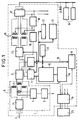
- Figure 1 shows a diagram of a main terminal according to the invention.
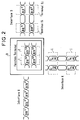
- Figure 2 shows a block diagram of the B channel connections through a main terminal.
- the user terminal 0, known as the main terminal, schematically presented in FIG. 1, corresponds for example to a multifunction telephone set with for example a fax and / or an image display screen and possibly in this case a device for taking view, it is intended to be connected at the level of the reference point U of a digital network with ISDN service integration, it is of course likely to be connected at the level of a corresponding reference point of a digital network private with integration of RPIS services.
- this main terminal 0 comprises an interface 1, of type U, intended to be connected to a remote line terminal, not shown, to which it is connected via a digital subscriber line 2, via a connector 3.
- This subscriber line 2 is provided in a manner known per se to allow a useful speed of 144 kbit / s corresponding to a transmission structure composed of two B channels and a D channel, as mentioned above, in each of the two opposite directions of transmission.
- the connector 3 is connected to the primary of an isolation transformer 4 so as to allow a bidirectional transmission of digital data via this primary and the secondary of the transformer 4, between the main terminal 0 and the line terminal, remote, via subscriber line 2.
- the primary of the transformer 4 has two separate windings to allow power to the main terminal 0 by the wires of the subscriber line 2, via a conventional circuit 5 for protection against overvoltages and overcurrents and a continuous-continuous step-down converter 6.
- the primary of the transformer 4 is connected to a transceiver circuit 7 with echo canceller designed to interface a subscriber line at the basic access level, such as for example a PEB 2091 circuit marketed by the company SIEMENS AKTIENGESELLSCHAFT, which allows a bidirectional transmission of digital data at a reference point U, according to the standards for physical layer 1 of the American National Standards Institute (ANSI).
- ANSI American National Standards Institute
- the transceiver 7 is connected, on the one hand, to a communications controller circuit 8 which performs the functions linked to the link layer 2, that is to say those relating to the transfer of information passing through the channel D, on the other hand to a time switching matrix 11.
- the communications controller 8 comprises an access port making it possible to connect it to a management processor 9 of the main terminal 0, via an operating bus 10 for the exchange of signaling information transmitted on channel D and an access port, of the serial type, by which it is connected on the one hand to the transceiver 7.
- the processor 9 is conventionally accompanied by a set 20 of read-only and / or random-access memories some of the latter being saved in a manner known per se.
- the communications controller 8 is for example a PEB 2070 model marketed by the company already mentioned above.
- the matrix 11 is for example of the gate network type and makes it possible to switch the information transmitted by channels B between the transceiver 7 and a digital station arrangement 12 or a subscriber access circuit 13, under the control of the processor. management 9 to which the matrix 11 is connected by the bus 10.
- the arrangement 12 and the access circuit are each connected by a synchronous serial link to the matrix 11.
- the arrangement 12 is for example of a conventional type where a cofidec circuit, not shown, ensures the conversion of the digital signals coming from a channel B into analog signals reproducible by the audio equipment of the station, such as telephone handset or loudspeaker.
- loudspeaker comprised by the main terminal 0, as well as the reverse conversion of the analog signals picked up by a microphone of the main terminal 0 into coded signals MIC capable of being transmitted, via a B channel.
- the arrangement 12 also comprises in a known manner in this case the various circuits and devices necessary, such as a ringing circuit, a call dialing circuit and the like, it is likely to include optional auxiliary circuits, such as a sound amplification circuit, a hands-free operating circuit or a circuit for a cordless handset, which, customary in this field, are not shown here.
- auxiliary circuits such as a sound amplification circuit, a hands-free operating circuit or a circuit for a cordless handset, which, customary in this field, are not shown here.
- the arrangement 12 may also include circuits and devices allowing the display on screen of images possibly transmitted with corresponding sounds by means of one or two B channels, or even for the analysis and reproduction of documents, it may also include circuits and devices for shooting if the terminal offers videophone possibilities, the image data and its correspondent being provided transmitted in a similar manner to that provided above for the images to be displayed.
- the arrangement 12 is supervised by the processor 9 of the main terminal 0, via the bus 10 to which it is connected by a port; the bus 10 also serves other conventional devices commonly included by the terminals and which are present here in the main terminal 0, such as a keyboard 21, in particular for dialing and a keyboard. display 22 for example with liquid crystal, these devices not directly related to the invention being recalled only for the record.
- An adapter 14 is connected to the matrix port 10 serving the equipment 12, in parallel with the latter, it is intended to allow the connection of an external telephone terminal 23 at a reference point R, as defined above. - above in connection with the ISDN structure.
- This adapter 14 is for example an adapter for videotex terminal capable of transmitting and receiving alphanumeric data in the form of multifrequency signals via an analog type telephone line.
- the adapter 14 includes a not shown cofidec which is connected to the matrix port 10 in parallel with the cofidec that the arrangement 12 includes, the connection produced remaining of the synchronous serial type, the data being simultaneously transmitted by the common port of the matrix 10 towards the equipment 12 and towards the adapter 14 or alternatively emitted by one or the other of these, towards this common port.
- the adapter 14 also comprises, in this case, a two-wire / four-wire circuit connected by the latter to the cofidec it contains and by the two wires to a connector 15 allowing the connection of the external terminal 23, here videotex.
- the latter receives and transmits analog audio signals, which differ from those transmitted by a conventional analog telephone line insofar as they are not combined with a direct supply current and which correspond to the alphanumeric data transmitted in multifrequency code in the application example mentioned above.
- the adapter 14 is connected to the equipment 12 by a link which is used to transmit the tones modem for translating the latter into sound form intended for the user by means of or one of the sound transducers which the main terminal 0 includes.
- the connector 15 is connected to the processor 9 by a serial type link to allow signaling exchanges between the external terminal 23 and this processor 9.
- the connector 15 also includes terminals making it possible to supply the external terminal 23 at least partially and depending on the case from the main terminal 0 or, conversely, to provide partial supply in the opposite direction to the main terminal by the external terminal, the usual circuits necessary are not shown here insofar as they are well known to those skilled in the art.
- the subscriber access circuit 13 ensures an electrical adaptation of four-wire transmission to allow the connection of voice-data terminals, preferably of ISDN type, such as 24, to the main terminal 0, as well as the functions of communications controller for these terminals, it is for example a PEB 2085 circuit marketed by the same company as the two PEB 2070 and PEB 2091 circuits mentioned above.
- a transformer 16 is connected to the four wires of the two-wire / four-wire circuit of the subscriber access circuit 13, it therefore has two separate windings for both the primary and the secondary.
- the four ends of the two windings, here called secondary, not connected to the subscriber circuit 13 are connected to four terminals of a connector 17 by a four-wire connection, this connector corresponding to the reference point level S and being capable of constituting an access port for a so-called type S bus to which one to several external terminals 24, of the ISDN type, are capable of being connected in parallel.
- the connector 17 also includes terminals making it possible to supply at least partially the external terminal or terminals 24 connected by means of a phantom circuit connected to the midpoint of each of the two so-called secondary windings of the transformer 16, via a conventional circuit of regulation and protection 18, as well as a possible external terminal 23 connected to the connector 15 whose supply terminals are then connected by conductors here referenced A to terminals of the connector 17.
- terminals of the connector 17 which supply the circuit 18 and the connector 15, via the wires A are themselves connected to a DC power supply which is not shown and which is connected with the bus link S to the connector 17 .
- a circuit 19 for detecting the presence of supply is connected to the output wires of circuit 18 which supplies the phantom circuit to signal to the transceiver circuit 7 for signaling purposes any supply faults affecting the bus S.
- the use of the main terminal 0 taken in isolation is practically identical to that of an ISDN terminal station which would be connected at the level of a reference point S of the ISDN structure, the main terminal 0 then exploiting one or two voice-data channels.
- B bidirectional link 2 and the corresponding D channel, the different channels unidirectional concerned being referenced B1E U B2E U in Figure 2 for the data transmitted from the main terminal 0 and B1R U, B2R U for data to be received, via link 2.
- the unidirectional channels operated by the main terminal 0 for its own needs are referenced here B1E Tx, B2E Tx, Tx B1R, B2R Tx.
- the unidirectional channels which can be used by the external terminals 24, of the ISDN type, are referenced BiE S , BjE S , BiR S , BjR S , while those which can be used by the external terminal 23 connected at the interface level R are referenced BiE C , BjE C , BiR C , BjR C.
- bidirectional data channel B1E U -B1R U and B2E U -B2R U of the digital subscriber link 2 to establish communication by two B channels, with either the main terminal 0 or the one of the terminals 24 or two communications on a B channel involving two of the interconnected terminals 0, 23, 24.
- the operation of the data-channel channels B, available on the digital subscriber link 2, by the main terminal 0 has no influence on any local communications between external terminals 24 or 23 and 24.
- the main terminal 0 thus produced also makes it possible to deport the terminals 24, if necessary, by allowing the remote deportment of the bus S, the usual range of which is limited to a distance of the order of 150 meters for a bus without connection restriction one kilometer for a single terminal 24.
Landscapes
- Engineering & Computer Science (AREA)
- Computer Networks & Wireless Communication (AREA)
- Exchange Systems With Centralized Control (AREA)
- Microcomputers (AREA)
- Communication Control (AREA)
- Telephonic Communication Services (AREA)
- Data Exchanges In Wide-Area Networks (AREA)
- Mobile Radio Communication Systems (AREA)
- Interface Circuits In Exchanges (AREA)
- Use Of Switch Circuits For Exchanges And Methods Of Control Of Multiplex Exchanges (AREA)
- Circuits Of Receivers In General (AREA)
- Credit Cards Or The Like (AREA)
Applications Claiming Priority (2)
| Application Number | Priority Date | Filing Date | Title |
|---|---|---|---|
| FR9013804 | 1990-11-07 | ||
| FR909013804A FR2668871B1 (fr) | 1990-11-07 | 1990-11-07 | Terminal principal, pour reseau numerique a integration de services. |
Publications (2)
| Publication Number | Publication Date |
|---|---|
| EP0486864A1 true EP0486864A1 (de) | 1992-05-27 |
| EP0486864B1 EP0486864B1 (de) | 1997-03-19 |
Family
ID=9401938
Family Applications (1)
| Application Number | Title | Priority Date | Filing Date |
|---|---|---|---|
| EP91118764A Expired - Lifetime EP0486864B1 (de) | 1990-11-07 | 1991-11-04 | Hauptendstelle für ein dienstintegrierendes Digitalnetz |
Country Status (5)
| Country | Link |
|---|---|
| EP (1) | EP0486864B1 (de) |
| AT (1) | ATE150607T1 (de) |
| DE (1) | DE69125246T2 (de) |
| ES (1) | ES2100192T3 (de) |
| FR (1) | FR2668871B1 (de) |
Citations (2)
| Publication number | Priority date | Publication date | Assignee | Title |
|---|---|---|---|---|
| US4792800A (en) * | 1985-08-01 | 1988-12-20 | Kobusai Denshin Denwa Co., Ltd. | Local communication system among ISDN terminal equipments |
| GB2220325A (en) * | 1988-06-07 | 1990-01-04 | Nec Corp | ISDN network termination unit |
-
1990
- 1990-11-07 FR FR909013804A patent/FR2668871B1/fr not_active Expired - Fee Related
-
1991
- 1991-11-04 DE DE69125246T patent/DE69125246T2/de not_active Expired - Fee Related
- 1991-11-04 EP EP91118764A patent/EP0486864B1/de not_active Expired - Lifetime
- 1991-11-04 AT AT91118764T patent/ATE150607T1/de not_active IP Right Cessation
- 1991-11-04 ES ES91118764T patent/ES2100192T3/es not_active Expired - Lifetime
Patent Citations (2)
| Publication number | Priority date | Publication date | Assignee | Title |
|---|---|---|---|---|
| US4792800A (en) * | 1985-08-01 | 1988-12-20 | Kobusai Denshin Denwa Co., Ltd. | Local communication system among ISDN terminal equipments |
| GB2220325A (en) * | 1988-06-07 | 1990-01-04 | Nec Corp | ISDN network termination unit |
Non-Patent Citations (1)
| Title |
|---|
| PROCEEDINGS OF THE INTERNATIONAL SYMPOSIUM ON SUBSCRIBER LOOPS AND SERVICES, Tokyo, 29 septembre - 3 octobre 1986, pages 150-155; M. FUJIOKA et al.: "Integrated call control and ISDN basic access interface system for advanced services" * |
Also Published As
| Publication number | Publication date |
|---|---|
| FR2668871A1 (fr) | 1992-05-07 |
| EP0486864B1 (de) | 1997-03-19 |
| DE69125246T2 (de) | 1997-06-26 |
| ATE150607T1 (de) | 1997-04-15 |
| FR2668871B1 (fr) | 1994-09-16 |
| ES2100192T3 (es) | 1997-06-16 |
| DE69125246D1 (de) | 1997-04-24 |
Similar Documents
| Publication | Publication Date | Title |
|---|---|---|
| US6167043A (en) | Method and system for small office and home office telephone private branch exchange allowing simultaneous data and voice communications | |
| US5862134A (en) | Single-wiring network for integrated voice and data communications | |
| US5774526A (en) | Reconfigurable on-demand telephone and data line system | |
| US5142571A (en) | Digital telephone set having an emergency switching function and communication system having the same | |
| MXPA01000781A (es) | Sistema de telecomunicaciones metodo y unidad de abonado para ser utilizada en el mismo. | |
| US6868081B1 (en) | Method and apparatus for simultaneous multiline phone and data services over a single access facility | |
| EP1385320B1 (de) | Merfach-Netzzugangs IP-Telefon | |
| EP0684722B1 (de) | Umlenkschnittstelle zwischen zwei Fernsprechleitungen und einer Fernsprechstelle | |
| JPH0818692A (ja) | 呼出し処理方法及び識別方法 | |
| US20050073995A1 (en) | Voice-over-internet protocol device | |
| KR100474912B1 (ko) | 듀얼 ip 폰 및 이를 이용한 통화 방법 | |
| EP0542705A2 (de) | Anordnung zur Anpassung einer Schnittstelle zu einem digitalen Netz | |
| US20010010716A1 (en) | Premises gateway and premises network interfaces for accessing subscriber premises equipment and communication networks using ring suppression | |
| EP0254920B1 (de) | System zum Anschluss von Telefonteilnehmern, rund um eine digitale Zeitmultiplexvermittlungsanlage gestaltet | |
| EP0486864B1 (de) | Hauptendstelle für ein dienstintegrierendes Digitalnetz | |
| EP0487416B1 (de) | Verbindungsanordnung eines analogen Endgerätes für ein Dienstintegrierendes Digitalnetz und Adapter für eine solche Anordnung | |
| RU2133557C1 (ru) | Телефонная сеть структурированного объекта и система телефонной связи между удаленными структурированными объектами, использующими указанную сеть | |
| JPH0548573A (ja) | Isdn用電話装置 | |
| JPH11285037A (ja) | 端末アダプタ装置 | |
| JP4280532B2 (ja) | VoIP用ISDNアダプタおよびVoIP通話システム | |
| WO2004049655A1 (en) | System and method for voice over ip communication | |
| KR100283759B1 (ko) | 아날로그 팩시밀리 시스템의 전화/팩시밀리 공용 인터페이스 | |
| AU618852B2 (en) | Digital telephone set having an emergency switching function and communication system having the same | |
| CA2227267C (en) | Reconfigurable on-demand telephone and data line system | |
| JPH0332257B2 (de) |
Legal Events
| Date | Code | Title | Description |
|---|---|---|---|
| PUAI | Public reference made under article 153(3) epc to a published international application that has entered the european phase |
Free format text: ORIGINAL CODE: 0009012 |
|
| AK | Designated contracting states |
Kind code of ref document: A1 Designated state(s): AT BE CH DE DK ES FR GB IT LI NL SE |
|
| 17P | Request for examination filed |
Effective date: 19921124 |
|
| 17Q | First examination report despatched |
Effective date: 19950221 |
|
| GRAG | Despatch of communication of intention to grant |
Free format text: ORIGINAL CODE: EPIDOS AGRA |
|
| GRAH | Despatch of communication of intention to grant a patent |
Free format text: ORIGINAL CODE: EPIDOS IGRA |
|
| GRAH | Despatch of communication of intention to grant a patent |
Free format text: ORIGINAL CODE: EPIDOS IGRA |
|
| GRAA | (expected) grant |
Free format text: ORIGINAL CODE: 0009210 |
|
| AK | Designated contracting states |
Kind code of ref document: B1 Designated state(s): AT BE CH DE DK ES FR GB IT LI NL SE |
|
| PG25 | Lapsed in a contracting state [announced via postgrant information from national office to epo] |
Ref country code: DK Effective date: 19970319 |
|
| REF | Corresponds to: |
Ref document number: 150607 Country of ref document: AT Date of ref document: 19970415 Kind code of ref document: T |
|
| REG | Reference to a national code |
Ref country code: CH Ref legal event code: EP |
|
| REG | Reference to a national code |
Ref country code: CH Ref legal event code: NV Representative=s name: GEC ALSTHOM (SUISSE) S.A. DEPARTEMENT DES BREVETS |
|
| REF | Corresponds to: |
Ref document number: 69125246 Country of ref document: DE Date of ref document: 19970424 |
|
| ITF | It: translation for a ep patent filed | ||
| REG | Reference to a national code |
Ref country code: ES Ref legal event code: FG2A Ref document number: 2100192 Country of ref document: ES Kind code of ref document: T3 |
|
| GBT | Gb: translation of ep patent filed (gb section 77(6)(a)/1977) |
Effective date: 19970613 |
|
| PLBE | No opposition filed within time limit |
Free format text: ORIGINAL CODE: 0009261 |
|
| STAA | Information on the status of an ep patent application or granted ep patent |
Free format text: STATUS: NO OPPOSITION FILED WITHIN TIME LIMIT |
|
| 26N | No opposition filed | ||
| PGFP | Annual fee paid to national office [announced via postgrant information from national office to epo] |
Ref country code: GB Payment date: 20011012 Year of fee payment: 11 |
|
| PGFP | Annual fee paid to national office [announced via postgrant information from national office to epo] |
Ref country code: CH Payment date: 20011016 Year of fee payment: 11 |
|
| PGFP | Annual fee paid to national office [announced via postgrant information from national office to epo] |
Ref country code: AT Payment date: 20011026 Year of fee payment: 11 |
|
| PGFP | Annual fee paid to national office [announced via postgrant information from national office to epo] |
Ref country code: NL Payment date: 20011031 Year of fee payment: 11 Ref country code: DE Payment date: 20011031 Year of fee payment: 11 |
|
| PGFP | Annual fee paid to national office [announced via postgrant information from national office to epo] |
Ref country code: SE Payment date: 20011105 Year of fee payment: 11 |
|
| PGFP | Annual fee paid to national office [announced via postgrant information from national office to epo] |
Ref country code: FR Payment date: 20011106 Year of fee payment: 11 |
|
| PGFP | Annual fee paid to national office [announced via postgrant information from national office to epo] |
Ref country code: BE Payment date: 20011114 Year of fee payment: 11 |
|
| PGFP | Annual fee paid to national office [announced via postgrant information from national office to epo] |
Ref country code: ES Payment date: 20011119 Year of fee payment: 11 |
|
| REG | Reference to a national code |
Ref country code: GB Ref legal event code: IF02 |
|
| PG25 | Lapsed in a contracting state [announced via postgrant information from national office to epo] |
Ref country code: GB Free format text: LAPSE BECAUSE OF NON-PAYMENT OF DUE FEES Effective date: 20021104 Ref country code: AT Free format text: LAPSE BECAUSE OF NON-PAYMENT OF DUE FEES Effective date: 20021104 |
|
| PG25 | Lapsed in a contracting state [announced via postgrant information from national office to epo] |
Ref country code: SE Free format text: LAPSE BECAUSE OF NON-PAYMENT OF DUE FEES Effective date: 20021105 Ref country code: ES Free format text: LAPSE BECAUSE OF NON-PAYMENT OF DUE FEES Effective date: 20021105 |
|
| PG25 | Lapsed in a contracting state [announced via postgrant information from national office to epo] |
Ref country code: LI Free format text: LAPSE BECAUSE OF NON-PAYMENT OF DUE FEES Effective date: 20021130 Ref country code: CH Free format text: LAPSE BECAUSE OF NON-PAYMENT OF DUE FEES Effective date: 20021130 Ref country code: BE Free format text: LAPSE BECAUSE OF NON-PAYMENT OF DUE FEES Effective date: 20021130 |
|
| BERE | Be: lapsed |
Owner name: *ALCATEL BUSINESS SYSTEMS Effective date: 20021130 |
|
| PG25 | Lapsed in a contracting state [announced via postgrant information from national office to epo] |
Ref country code: NL Free format text: LAPSE BECAUSE OF NON-PAYMENT OF DUE FEES Effective date: 20030601 |
|
| PG25 | Lapsed in a contracting state [announced via postgrant information from national office to epo] |
Ref country code: DE Free format text: LAPSE BECAUSE OF NON-PAYMENT OF DUE FEES Effective date: 20030603 |
|
| GBPC | Gb: european patent ceased through non-payment of renewal fee | ||
| EUG | Se: european patent has lapsed | ||
| REG | Reference to a national code |
Ref country code: CH Ref legal event code: PL |
|
| PG25 | Lapsed in a contracting state [announced via postgrant information from national office to epo] |
Ref country code: FR Free format text: LAPSE BECAUSE OF NON-PAYMENT OF DUE FEES Effective date: 20030731 |
|
| NLV4 | Nl: lapsed or anulled due to non-payment of the annual fee |
Effective date: 20030601 |
|
| REG | Reference to a national code |
Ref country code: FR Ref legal event code: ST |
|
| REG | Reference to a national code |
Ref country code: ES Ref legal event code: FD2A Effective date: 20031213 |
|
| PG25 | Lapsed in a contracting state [announced via postgrant information from national office to epo] |
Ref country code: IT Free format text: LAPSE BECAUSE OF NON-PAYMENT OF DUE FEES;WARNING: LAPSES OF ITALIAN PATENTS WITH EFFECTIVE DATE BEFORE 2007 MAY HAVE OCCURRED AT ANY TIME BEFORE 2007. THE CORRECT EFFECTIVE DATE MAY BE DIFFERENT FROM THE ONE RECORDED. Effective date: 20051104 |