EP0486789B1 - A modular system for obtaining equipped walls and work-benches, in particular for use in laboratories - Google Patents
A modular system for obtaining equipped walls and work-benches, in particular for use in laboratories Download PDFInfo
- Publication number
- EP0486789B1 EP0486789B1 EP91116296A EP91116296A EP0486789B1 EP 0486789 B1 EP0486789 B1 EP 0486789B1 EP 91116296 A EP91116296 A EP 91116296A EP 91116296 A EP91116296 A EP 91116296A EP 0486789 B1 EP0486789 B1 EP 0486789B1
- Authority
- EP
- European Patent Office
- Prior art keywords
- wall
- beams
- holders
- furniture
- shaped
- Prior art date
- Legal status (The legal status is an assumption and is not a legal conclusion. Google has not performed a legal analysis and makes no representation as to the accuracy of the status listed.)
- Expired - Lifetime
Links
Images


Classifications
-
- B—PERFORMING OPERATIONS; TRANSPORTING
- B25—HAND TOOLS; PORTABLE POWER-DRIVEN TOOLS; MANIPULATORS
- B25H—WORKSHOP EQUIPMENT, e.g. FOR MARKING-OUT WORK; STORAGE MEANS FOR WORKSHOPS
- B25H1/00—Work benches; Portable stands or supports for positioning portable tools or work to be operated on thereby
- B25H1/12—Work benches; Portable stands or supports for positioning portable tools or work to be operated on thereby with storage compartments
-
- A—HUMAN NECESSITIES
- A47—FURNITURE; DOMESTIC ARTICLES OR APPLIANCES; COFFEE MILLS; SPICE MILLS; SUCTION CLEANERS IN GENERAL
- A47B—TABLES; DESKS; OFFICE FURNITURE; CABINETS; DRAWERS; GENERAL DETAILS OF FURNITURE
- A47B47/00—Cabinets, racks or shelf units, characterised by features related to dismountability or building-up from elements
- A47B47/0091—Modular arrangements of similar assemblies of elements
-
- A—HUMAN NECESSITIES
- A47—FURNITURE; DOMESTIC ARTICLES OR APPLIANCES; COFFEE MILLS; SPICE MILLS; SUCTION CLEANERS IN GENERAL
- A47B—TABLES; DESKS; OFFICE FURNITURE; CABINETS; DRAWERS; GENERAL DETAILS OF FURNITURE
- A47B57/00—Cabinets, racks or shelf units, characterised by features for adjusting shelves or partitions
- A47B57/30—Cabinets, racks or shelf units, characterised by features for adjusting shelves or partitions with means for adjusting the height of detachable shelf supports
- A47B57/40—Cabinets, racks or shelf units, characterised by features for adjusting shelves or partitions with means for adjusting the height of detachable shelf supports consisting of hooks coacting with openings
- A47B57/42—Cabinets, racks or shelf units, characterised by features for adjusting shelves or partitions with means for adjusting the height of detachable shelf supports consisting of hooks coacting with openings the shelf supports being cantilever brackets
-
- A—HUMAN NECESSITIES
- A47—FURNITURE; DOMESTIC ARTICLES OR APPLIANCES; COFFEE MILLS; SPICE MILLS; SUCTION CLEANERS IN GENERAL
- A47B—TABLES; DESKS; OFFICE FURNITURE; CABINETS; DRAWERS; GENERAL DETAILS OF FURNITURE
- A47B96/00—Details of cabinets, racks or shelf units not covered by a single one of groups A47B43/00 - A47B95/00; General details of furniture
- A47B96/06—Brackets or similar supporting means for cabinets, racks or shelves
- A47B96/067—Horizontal rails as suspension means in a cantilever arrangement
-
- A—HUMAN NECESSITIES
- A47—FURNITURE; DOMESTIC ARTICLES OR APPLIANCES; COFFEE MILLS; SPICE MILLS; SUCTION CLEANERS IN GENERAL
- A47F—SPECIAL FURNITURE, FITTINGS, OR ACCESSORIES FOR SHOPS, STOREHOUSES, BARS, RESTAURANTS OR THE LIKE; PAYING COUNTERS
- A47F5/00—Show stands, hangers, or shelves characterised by their constructional features
- A47F5/08—Show stands, hangers, or shelves characterised by their constructional features secured to the wall, ceiling, or the like; Wall-bracket display devices
- A47F5/0807—Display panels, grids or rods used for suspending merchandise or cards supporting articles; Movable brackets therefor
- A47F5/0846—Display panels or rails with elongated channels; Sliders, brackets, shelves, or the like, slidably attached therein
-
- B—PERFORMING OPERATIONS; TRANSPORTING
- B01—PHYSICAL OR CHEMICAL PROCESSES OR APPARATUS IN GENERAL
- B01L—CHEMICAL OR PHYSICAL LABORATORY APPARATUS FOR GENERAL USE
- B01L9/00—Supporting devices; Holding devices
- B01L9/02—Laboratory benches or tables; Fittings therefor
Definitions
- This invention is relating to a modular system for obtaining benches and equipped walls designed for use in laboratories or the like.
- a system comprising a modular structure constructed of uprights and crosspieces to which beams are fixed permitting supports for pieces of furniture, working tables, shelves, etc., to be fitted in a slidable manner thereto.
- the equipped wall can also have utility panels mounted to it which include connection means for water, gas, electricity, as well as the associated discharge means, all of which are entirely received inside the wall in a flush-relationship with it.
- Equipped walls and associated workbenches are already known and are, for example, used in laboratories or the like in order to obtain work stations each provided with the required utilities.
- These equipped walls are constructed of structure units that are mounted in proper locations and to which the shelves and the pieces of furniture forming the workbenches are fitted.
- the structure of said equipped walls includes ducts and passages for water and gas inlet pipes, for electricity supply means, and all what is necessary for the employed equipment to operate.
- the fluid supply devices in particular cocks, etc.., are fitted to the wall so as to slightly project therefrom.
- the discharge means are, therefore, generally built in the workbenches which are fixed and connected to discharge pipes in the wall.
- US-A- 4.320.935 discloses a modular system for constructing equipped walls and workbenches comprising a plurality of modular uprights imbedded in a wall to provide the bearing structure of an equipped wall, said modular system including beams fastened to said structure, which permit pieces of furniture and fittings to be mounted in whatever position to it.
- the invention relates to a modular system for obtaining equipped walls according to the appended claims.
- a set of section members are used to provide a corresponding set of modular uprights and crosspieces and these are assembled together to obtain the bearing structure for an equipped wall in the inside of which there are arranged ducts for the different utilities, while working tables and associated pieces of furniture - which are also of modular type and make a part of the invention - are mounted to the same equipped wall.
- Figures 1 and 2 show, by way of example, some solutions that can be conceived in accordance with the system of the invention.
- a partly open wall broadly designated by reference number 1, in the inside of which fluid inlet pipes 2, discharge pipes 3, electrical cables, etc... can run.
- the bearing structure of the wall is constructed of a plurality of uprights 4 interconnected by crosspieces 5.
- section members have a plurality of slots 6 centrally formed along the length thereof and two memori of slots 7 are provided on the sides. Slots 6 receive the fastenings for both the crosspieces and the beams supporting the workroom furnishings, while slots 7 are for fitting panels carrying the various utilities to the equipped wall.
- crosspieces and the uprights are provided on part of their height with greater size openings, designated by reference number 8 figure 2b, to permit pipes to pass therethrough.
- Figures 4a and 4b show a system for connecting the crosspieces and uprights to each other.
- a C-shaped member as indicated by reference number 9, is fixed in a known manner to the ends of each crosspiece, and the legs of this C-shaped member, which are jutting out with respect to the end-most portion of crosspiece, have slits formed adjacent their ends to define a hook-like element for fitting into upright slots 7.
- a sliding block 10 is mounted inside the legs of member 9 and has a threading therein for engaging a screw 11 or the like.
- This beam 100 is substantially quadrangular in cross-section and is provided on each side with a longitudinal downwardly widening groove 14. As a result, the sidewalls of grooves 14 each define an in-turned rim 15.
- the beams are attached to the structure of the equipped wall or to a framework intended to form a vertical wall of a bench.
- the devices permitting connection to the structure of an equipped wall are shown figure 14 and include a support 16 which has a pair of hook-shaped extensions 17 for fitting into central upright slots 6, and to which a plate 18 is attached for mounting a beam thereto.
- This latter is inserted at its end in a head member or support 19 which is properly shaped so as to enable it to be introduced, in part, into a central opening in plate 18 while the other side thereof receives a cover 20, whereupon the entire assembly can be locked in position by the aid of a screw 21 (these devices are best seen figure 5 where an angle member 22 has been substituted for plate 10 and will be described in more details below).
- plates 23 or the like are fitted into grooves 14 and are then locked in place by the aid of screws or a similar fastening system which also engages the support 19.
- the angle member 22 serves as the connecting member for the components of a bench-wall structure which is best seen figure 7.
- the bench walls are each constructed of a set of sections 24 connected together by means of angle members 22 two of which (figure 8) are in turn fixed to hooking devices 16 similar to that described in connection with figure 12.
- Each carriage 32 comprises a suitably shaped section member which is provided with a handle 34 and on which a pair of wheels 35 are mounted, these wheels being able to run in upper groove 14 of the associated beam.
- the lower support carriage is provided with wheels which can run in the corresponding beam.
- the wall can then, in addition to receive shelves, supports etc.., be fitted with utility panels which may include devices for supplying electricity and admitting utility fluids.
- the water supply panel has a wall, again designated by reference number 36, which defines a variable depth cavity where cocks 39 are installed, the bottom of the cavity forming a basin 40 leading to a discharge pipe.
- Such a fluid control panel is shown figure 13a in a perspective view.
- an electrical panel a rear part of which is seen figure 11 and is shaped so as to have, for example in a middle portion thereof, a reduced-depth region 41 providing a given space for passage of any cables leading to further panels placed in an upper area.
- bracket means 42 that are shaped so as to define a pair of arms capable of engaging around an associated beam through a catch means 43 which enters one beam groove 14 to lock the bracket against rotation while permitting it to be slidingly moved along the beam to fix the bracket in a most convenient position thereon.
- these fixed brackets may be used for securing in place reagent tables (figure 13d), book shelves (figure 13e), computer supports (figure 13f), bottle trays (figure 13g).
- multipurpose lamps (figure 13h) or other fixtures as currently used in laboratories, can be fitted in place.
- the peculiar mounting system used for the pieces of furniture which are at any time kept in spaced relationship with both the floor and the wall, permits efficient constant cleaning to be maintained in a room: an imperative requisite, for example, in case of aseptic rooms.
- the utility panels all of which are the same in size and, thus, interchangeable, can be easily moved to, and relocated in other wall areas, thereby to vary as necessary the distribution of the utilities.
- the peculiar shape of the beams enables rapid and easy mounting not only of pieces of furniture and workbenches, but also of a wide variety of fittings and accessories which can be fitted in place directly by an user in a fast and simple manner, without having to accurately plan each working station at the time when designing an equipped wall, that is when it is not yet possible to precisely know what about the definitive, very requirements of an user in connection with that equipped wall.
Landscapes
- Engineering & Computer Science (AREA)
- Mechanical Engineering (AREA)
- Health & Medical Sciences (AREA)
- Clinical Laboratory Science (AREA)
- Chemical & Material Sciences (AREA)
- Chemical Kinetics & Catalysis (AREA)
- Devices For Use In Laboratory Experiments (AREA)
- Cultivation Receptacles Or Flower-Pots, Or Pots For Seedlings (AREA)
- Assembled Shelves (AREA)
- Hydroponics (AREA)
- Details Of Rigid Or Semi-Rigid Containers (AREA)
- Spectrometry And Color Measurement (AREA)
- Apparatus Associated With Microorganisms And Enzymes (AREA)
- Preparation Of Compounds By Using Micro-Organisms (AREA)
Abstract
Description
- This invention is relating to a modular system for obtaining benches and equipped walls designed for use in laboratories or the like.
- More particularly, it deals with a system comprising a modular structure constructed of uprights and crosspieces to which beams are fixed permitting supports for pieces of furniture, working tables, shelves, etc., to be fitted in a slidable manner thereto.
- The equipped wall can also have utility panels mounted to it which include connection means for water, gas, electricity, as well as the associated discharge means, all of which are entirely received inside the wall in a flush-relationship with it.
- The above features ensure considerable flexibility in arrangement to give an user possibility of developing personalized furnishings with the utilities being positioned where they are of effective service, thereby permitting, for example, suitable supply and discharge means to be properly located adjacent each associated apparatus and benches or any other components to be varied in arrangement as a function of changes in instant requirements, without any expensive operation having to be resorted to.
- Equipped walls and associated workbenches are already known and are, for example, used in laboratories or the like in order to obtain work stations each provided with the required utilities.
- These equipped walls are constructed of structure units that are mounted in proper locations and to which the shelves and the pieces of furniture forming the workbenches are fitted.
- The structure of said equipped walls includes ducts and passages for water and gas inlet pipes, for electricity supply means, and all what is necessary for the employed equipment to operate.
- The fluid supply devices, in particular cocks, etc.., are fitted to the wall so as to slightly project therefrom. The discharge means are, therefore, generally built in the workbenches which are fixed and connected to discharge pipes in the wall.
- This solution,which has been long known and used has, however, limitations particularly in that an assembly, when mounted, is poor in flexibility and cannot be modified unless expensive operations are performed.
- This requires that a planning is made in advance about what the distribution of structure units inside a room and the arrangement of instruments on workbenches will have to be.
- Also, once the structure units are mounted, it is not possible to change their arrangement in order, for example,to adapt them to new rooms or to make them fit to different conditions of work which would have occurred meanwhile.
- For these reasons, a need is felt in this field for means permitting the above difficulties to be overcome by the obtention of modular structures which are easy to assemble and/ or to alter without expensive operations or skilled hands being necessary.
- Once a bench or wall is constructed, no alterations can be performed thereto, unless works of substantial importance are undertaken. Thus, by way of example, should it be decided that a water inlet is to be displaced, this would mean that the entire bench with the relative water outlet is to be displaced and a proper connection to pipes in the wall created, which is certainly a very complicated operation.
- The same holds when a working surface is to be displaced, such an operation requiring at present that change to the installation system should be made by skilled hands.
- US-A- 4.320.935 discloses a modular system for constructing equipped walls and workbenches comprising a plurality of modular uprights imbedded in a wall to provide the bearing structure of an equipped wall, said modular system including beams fastened to said structure, which permit pieces of furniture and fittings to be mounted in whatever position to it.
- It is an object of this invention to provide a modular system for obtaining benches and equipped walls, comprising a structure which includes uprights and crossmembers forming a wall framework to which beams are fitted for enabling benches or working surfaces with associated pieces of furniture to be mounted in a slidable manner thereto.
- The invention relates to a modular system for obtaining equipped walls according to the appended claims.
- These and other features and advantages of the present invention will be more clearly understood when reading the following detailed description,given by way of example only,with particular reference to the accompanying drawings, in which:-
- Figures 1 and 2 are perspective views of equipped walls provided with workbenches obtained by using components according to this invention;
- Figures 2a to 2c show, in sectional views, a section member used to form the support structure for an equipped wall;
- Figure 3 is a sectional view of a beam as used in equipped-wall structures according to the invention;
- Figure 4a is an exploded view showing devices for connecting and locking in place section members forming a structure;
- Figure 4b is a sectional view of the devices in figure 4a when mounted;
- Figure 5 is an exploded view of a joint in a structure according to the invention;
- Figure 6 is a detail view of a joint in a structre of the invention as shown sectionally;
- Figure 7 is an exploded view of a bench structure in a system according to the invention;
- Figure 8 is a detail sectional view of an equipped wall of the invention showing the region of the attaching devices for a bench in a vertical direction;
- Figures 9a and 9b are front and sectional view, respectively, showing devices for supporting a piece of furniture in a bench according to the invention;
- Figures 10a and 10b are sectional horizontal views showing two utility panels with associated fluid supply devices in an equipped wall of the invention;
- Figure 11 is a perspective view as seen from behind an utility panel to be fitted to an equipped wall according to the invention;
- Figure 12 is a detail view of a support for a shelf;
- Figures 13a to 13h schematically show various utility panels or accessory elements to be mounted to an equipped wall in accordance with the invention;
- Figure 14 is an exploded view of devices for connecting the bench-supporting beams to the wall.
- According to the system of the invention, a set of section members are used to provide a corresponding set of modular uprights and crosspieces and these are assembled together to obtain the bearing structure for an equipped wall in the inside of which there are arranged ducts for the different utilities, while working tables and associated pieces of furniture - which are also of modular type and make a part of the invention - are mounted to the same equipped wall.
- Figures 1 and 2 show, by way of example, some solutions that can be conceived in accordance with the system of the invention. In particular, shown to the right of figure 2, is a partly open wall, broadly designated by
reference number 1, in the inside of whichfluid inlet pipes 2, discharge pipes 3, electrical cables, etc... can run. - Still referring to figure 2, the bearing structure of the wall is constructed of a plurality of
uprights 4 interconnected bycrosspieces 5. - These uprights and crosspieces consist of a corresponding plurality of section members shown in figures 2a to 2c.
- More particularly, the section members have a plurality of
slots 6 centrally formed along the length thereof and two serie ofslots 7 are provided on the sides.Slots 6 receive the fastenings for both the crosspieces and the beams supporting the workroom furnishings, whileslots 7 are for fitting panels carrying the various utilities to the equipped wall. - Some of the crosspieces and the uprights are provided on part of their height with greater size openings, designated by reference number 8 figure 2b, to permit pipes to pass therethrough.
- Figures 4a and 4b show a system for connecting the crosspieces and uprights to each other.
- In particular, a C-shaped member, as indicated by
reference number 9, is fixed in a known manner to the ends of each crosspiece, and the legs of this C-shaped member, which are jutting out with respect to the end-most portion of crosspiece, have slits formed adjacent their ends to define a hook-like element for fitting intoupright slots 7. Asliding block 10 is mounted inside the legs ofmember 9 and has a threading therein for engaging ascrew 11 or the like. - On assembly (figure 4b), the ends of
legs 4 are inserted inslots 7 of an upright, whereupon tightening ofscrew 11 will urge theblock 10 to press it against the upright wall thereby to lock in position both the C-shaped member and the crosspiece attached thereto. - When the bearing structure for the equipped wall has been thus formed, a series of beams having the cross-section as shown figure 3 are attached to the structure.
- This
beam 100 is substantially quadrangular in cross-section and is provided on each side with a longitudinal downwardly wideninggroove 14. As a result, the sidewalls ofgrooves 14 each define an in-turnedrim 15. - It is to these beams that are then mounted the pieces of furniture, working tables and any fittings and accessories that are necessary to equip a workbench.
- For the sake of clarity, reference will be made in the following to "bench" to mean a working surface fixed to the wall, and to "piece of furniture" to mean any receptacle which may, or not, be closed and which is itself fixed to the associated wall, preferably beneath a working surface.
- The beams, one of which is broadly designated by 15, figure 5, are attached to the structure of the equipped wall or to a framework intended to form a vertical wall of a bench.
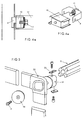
- The devices permitting connection to the structure of an equipped wall are shown figure 14 and include a
support 16 which has a pair of hook-shaped extensions 17 for fitting into centralupright slots 6, and to which aplate 18 is attached for mounting a beam thereto. This latter is inserted at its end in a head member orsupport 19 which is properly shaped so as to enable it to be introduced, in part, into a central opening inplate 18 while the other side thereof receives acover 20, whereupon the entire assembly can be locked in position by the aid of a screw 21 (these devices are best seen figure 5 where anangle member 22 has been substituted forplate 10 and will be described in more details below). - In order to prevent a
beam 100 from being drawn off asupport 19,plates 23 or the like are fitted intogrooves 14 and are then locked in place by the aid of screws or a similar fastening system which also engages thesupport 19. - As mentioned above, the
angle member 22 serves as the connecting member for the components of a bench-wall structure which is best seen figure 7. - The bench walls are each constructed of a set of
sections 24 connected together by means ofangle members 22 two of which (figure 8) are in turn fixed to hookingdevices 16 similar to that described in connection with figure 12. - Thus, a structure is obtained which is fixed, on one side, to the equipped wall and which can bear, on the other side,on the floor through
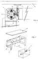
adjustable feet 25. - This structure permits a bench or support table 26 to be fixed thereto as well as a piece of furniture, such as that broadly indicated by 27, figure 7, to be mounted to same structure.
- In order to mount a bench (see figure 6), this is obtained by
fitting supports 28 tobeams 100. These supports 28 each comprise a section member or the like, which is of a shape to fit the profile of the associated beam, and which is locked in place on this latter by the aid ofscreews 29 engaging with corresponding clamping means 30 inserted inbeam grooves 14. - Then, adjustable feet or bearing means 31 for the working table 26, corresponding in number to supports 28, are screewed on these supports.
- The piece of
furniture 27 is, on the other hand, mounted tobeams 100 in a slidable manner as particularly shown figures 8, 9a and 9b. - More specifically, fitted to the structure of the piece of furniture are upper and
lower support carriages 32 and 33 (figures 9a and 8, respectively). Eachcarriage 32 comprises a suitably shaped section member which is provided with ahandle 34 and on which a pair ofwheels 35 are mounted, these wheels being able to run inupper groove 14 of the associated beam. Likewise, the lower support carriage is provided with wheels which can run in the corresponding beam. - This enables an operator to displace the piece of furniture to either sides of the workbench according to his particular requirements.
- The wall can then, in addition to receive shelves, supports etc.., be fitted with utility panels which may include devices for supplying electricity and admitting utility fluids.
- These panels are so constructed as to have said supply devices entirely received inside the wall in flush-relationship therewith.
- In figures 10a and 10b the panels with the devices for gas and water supply, respectively, are shown in sectional horizontal views.
- The panel in figure 10a has a
front wall 36 defining a recess within which thefluid supply cocks 37 are located, the fluid coming from aconduit 38 in the wall. - In a like manner, the water supply panel has a wall, again designated by
reference number 36, which defines a variable depth cavity wherecocks 39 are installed, the bottom of the cavity forming abasin 40 leading to a discharge pipe. - Such a fluid control panel is shown figure 13a in a perspective view.
- Also, shown in figure 13b is an electrical panel, a rear part of which is seen figure 11 and is shaped so as to have, for example in a middle portion thereof, a reduced-
depth region 41 providing a given space for passage of any cables leading to further panels placed in an upper area. - Finally, various other devices, as shown figures 13d to 13h, can be fitted to a concerned wall, particularly to
beams 100 thereof. - In order to mount these devices use may be made of bracket means 42 that are shaped so as to define a pair of arms capable of engaging around an associated beam through a catch means 43 which enters one
beam groove 14 to lock the bracket against rotation while permitting it to be slidingly moved along the beam to fix the bracket in a most convenient position thereon. - Then, these fixed brackets may be used for securing in place reagent tables (figure 13d), book shelves (figure 13e), computer supports (figure 13f), bottle trays (figure 13g).
- In a like manner, multipurpose lamps (figure 13h) or other fixtures as currently used in laboratories, can be fitted in place.
- It should be apparent from the above description that many advantages are offered by the system of the invention which has eliminated the net separation - inherent in prior art systems - between an equipped wall and a bench, thereby providing great flexibility in combining and arranging preassembled and presized structure units.
- The peculiar mounting system used for the pieces of furniture, which are at any time kept in spaced relationship with both the floor and the wall, permits efficient constant cleaning to be maintained in a room: an imperative requisite, for example, in case of aseptic rooms.
- The utility panels, all of which are the same in size and, thus, interchangeable, can be easily moved to, and relocated in other wall areas, thereby to vary as necessary the distribution of the utilities.
- The peculiar shape of the beams enables rapid and easy mounting not only of pieces of furniture and workbenches, but also of a wide variety of fittings and accessories which can be fitted in place directly by an user in a fast and simple manner, without having to accurately plan each working station at the time when designing an equipped wall, that is when it is not yet possible to precisely know what about the definitive, very requirements of an user in connection with that equipped wall.
- It is possible, when necessary, to operate a rearrangement of interior spaces without having recourse to any substantial masonry work , which is to entire benefit of an economical system.
- Obviously, many changes and modifications as well as many different embodiments based on the same principle as described above, may be thought by one skilled in the art, without departing from the spirit and scope of this invention, as defined in the appended claims.
Claims (14)
- A modular system for constructing equipped walls and workbenches, of the type comprising a plurality of modular uprights (4) and crosspieces (5), having openings for passage of cables and pipes therethrough to provide the bearing structure of an equipped wall, and beams (15,100) fastened to said structure which permit pieces of furniture and fittings to be mounted in whatever position to it, charactherized in that said beams are susbtantially quadrangular in cross-section and have a longitudinal groove (14) provided on each side thereof, the walls of said groove having an inturned portion at their outer edge providing a restriction at the surface of said groove so that the supports for pieces of furniture and fittings to be fitted to the associated wall, can be hooked up.
- The modular system for constructing walls equipped with workbenches according to claim 1, wherein said beams (15,100) are fixed to the bearing structure of the wall.
- The system of claims 1 and 2, wherein for connecting said crosspieces (5) and sait uprights (4) together, the system includes C-shaped holders (9) secured to the ends of the crosspieces with the legs of said C-shaped holders slightly projecting therefrom, said C-shaped holders having catch means at their ends for entering corresponding slots in the uprights and said C-shaped holders having each a screw (11) mounted thereon with possibility of rotation only , said screw engaging with a block (10) capable of sliding movement along the legs of said C-shaped holder.
- The system according to claim 1, wherein said beams (15,100) are mounted on supports comprising a plate (18) provided with catch means (17) that are capable of insertion in corresponding slots (7) in the uprights, said plate having an opening (18) for receiving a terminal fastener (19) into which an end of an associated beam can be fitted.
- The system according to claim 4, wherein in order to lock a beam in place in said terminal support element (19), the system includes metal plates (13) designed to enter the grooves (14) in the beam, said plates having a threaded hole for receiving a clamping screw, said clamping screw engaging into a hole in said terminal element.
- The system according to claims 1 and 2, wherein pieces of furniture are mounted to the structure by means of supports (32) that are each provided with wheels (35) capable of running in the grooves (14) of a corresponding beam to permit the piece of furniture to be translated along said beam.
- The system according to claim 6, wherein said supports are respectively attached to a piece of furniture at its upper corner adjacent the associated equipped wall, and at the opposite lower corner thereof.
- The system according to any preceding claim, wherein each workbench has a pair of sidewalls constructed of tubolar members (24) secured to connecting angle elements (22), said walls being attached to the equipped wall and being connected together by means of beams according to claim 3.
- The system according to claims 1 or 2, wherein the system includes support elements for the benches (26) which comprise holder means that are each provided with a bench-bearing foot (31) adjustable in height, said holders being shaped so as to fit around said beams arid being provided with locking means (29,30).
- The system according to claims 1 or 2, wherein the system includes holders (42) for enabling fittings to be mounted to the wall, said holders having a shaped formation at an attachment region thereof by which the holders can be fitted on said beams, said holders also being provided with catch means (43) that enter the grooves in said beams to lock the associated holder against rotation.
- The modular system for constructing equipped walls according to claims 1 to 3, wherein connection means for utilities are mounted to panels and the panels fitted to the wall structure, said connection means being entirely accommodated inside the wall thickness.
- The system according to claim 11, wherein said panels have a recessed wall so as to define a cavity in which fluid pipe connections and electrical connections can be arranged.
- The system according to claim 11, wherein the system includes panels having a built-in basin (40) for water discharge, said basin being contained within the overall dimension of the wall.
- The system according to claim 11 wherein the panel for electrical connections is shaped so as to define a reduced depth region (41) providing passage behind the panel for any cables leading to upper areas of the wall.
Applications Claiming Priority (2)
| Application Number | Priority Date | Filing Date | Title |
|---|---|---|---|
| IT2213290 | 1990-11-21 | ||
| IT02213290A IT1244081B (en) | 1990-11-21 | 1990-11-21 | MODULAR SYSTEM FOR THE REALIZATION OF EQUIPPED WALLS AND WORKBENCHES IN PARTICULAR FOR LABORATORIES. |
Publications (3)
| Publication Number | Publication Date |
|---|---|
| EP0486789A2 EP0486789A2 (en) | 1992-05-27 |
| EP0486789A3 EP0486789A3 (en) | 1992-12-30 |
| EP0486789B1 true EP0486789B1 (en) | 1996-08-21 |
Family
ID=11191972
Family Applications (1)
| Application Number | Title | Priority Date | Filing Date |
|---|---|---|---|
| EP91116296A Expired - Lifetime EP0486789B1 (en) | 1990-11-21 | 1991-09-25 | A modular system for obtaining equipped walls and work-benches, in particular for use in laboratories |
Country Status (8)
| Country | Link |
|---|---|
| US (2) | US5212915A (en) |
| EP (1) | EP0486789B1 (en) |
| AT (1) | ATE141471T1 (en) |
| DE (1) | DE69121522T2 (en) |
| DK (1) | DK0486789T3 (en) |
| ES (1) | ES2090197T3 (en) |
| GR (1) | GR3020837T3 (en) |
| IT (1) | IT1244081B (en) |
Families Citing this family (31)
| Publication number | Priority date | Publication date | Assignee | Title |
|---|---|---|---|---|
| IT1244081B (en) * | 1990-11-21 | 1994-07-05 | Arredi Tecnici Villa Spa | MODULAR SYSTEM FOR THE REALIZATION OF EQUIPPED WALLS AND WORKBENCHES IN PARTICULAR FOR LABORATORIES. |
| ES2088349B1 (en) * | 1993-08-12 | 1997-06-16 | Campillo Proyectos E Instalaci | PERFECTED FURNITURE CONSTRUCTION SYSTEM FOR LABORATORIES |
| US5429252A (en) * | 1993-11-02 | 1995-07-04 | Liu; Hung-Yang | Versatile rail for supporting objects in kitchen |
| US5622010A (en) * | 1995-08-18 | 1997-04-22 | Weber; Karl F. | Modular pharmacy |
| US6076308A (en) * | 1995-12-26 | 2000-06-20 | Steelcase Development Inc. | Partition panel system with adjustable overhead storage |
| DE19614370C1 (en) * | 1996-04-11 | 1997-12-18 | Waldner Laboreinrichtungen | Laboratory workplace |
| GB2315405A (en) * | 1996-07-24 | 1998-02-04 | Stephen John Wood | Pc workstation |
| BE1010811A5 (en) * | 1996-12-17 | 1999-02-02 | Barco Nv | LIGHT GUARD FOR ADDITION AND / OR superimposed DISPLAY DEVICES. |
| US5918432A (en) * | 1997-01-23 | 1999-07-06 | Mahone; Mark D | Shelving system and components thereof |
| US5918422A (en) * | 1997-05-14 | 1999-07-06 | Bucher, Jr.; Robert Joseph | Open office panel system |
| ES2163944B1 (en) * | 1998-05-21 | 2005-02-16 | Campillo Proyectos E Instalaciones, S.A. | PERFECTED MODULAR CONSTRUCTION SYSTEM OF FURNITURE FOR LABORATORIES. |
| EP1029480A1 (en) * | 1999-02-18 | 2000-08-23 | Fehlbaum & Co. | Sectional wall rail for mounting devices for display or goods |
| US7174678B2 (en) * | 1999-04-22 | 2007-02-13 | Hill-Rom Services, Inc. | Modular patient room |
| US6405491B1 (en) | 1999-04-22 | 2002-06-18 | Hill-Rom Services, Inc. | Modular patient room |
| DE10154128B4 (en) | 2001-10-25 | 2009-09-03 | Hermann Schaffitzel | Media cell for a laboratory or the like |
| US6851226B2 (en) * | 2002-02-15 | 2005-02-08 | Steelcase Development Corporation | Partition panel with modular appliance mounting arrangement |
| US6857712B1 (en) * | 2002-04-04 | 2005-02-22 | Forecast Consoles, Inc. | Multi-media workstation having a master rail system |
| EP1405673A1 (en) * | 2002-10-04 | 2004-04-07 | S+B International B.V. | Support plate having a service unit |
| EP1419822B1 (en) * | 2002-11-12 | 2007-08-15 | Mobilab Proyectos, S.L. | Laboratory furniture building system |
| ES2234374B1 (en) * | 2002-11-12 | 2006-05-16 | Julian Romero Muñoz | CONSTRUCTION SYSTEM FOR LABORATORY FURNITURE-SHELF. |
| US8091312B2 (en) * | 2003-12-31 | 2012-01-10 | Harold Simpson, Inc. | Standing seam panel clips |
| US20050193644A1 (en) * | 2003-12-31 | 2005-09-08 | Simpson Harold G. | Standing seam panel clips |
| US7628563B2 (en) * | 2007-03-16 | 2009-12-08 | Winkler John M | Fitting for a T-slot structure |
| DE102009002454A1 (en) | 2009-04-17 | 2010-10-28 | Waldner Laboreinrichtungen Gmbh & Co. Kg | Media channel for a laboratory device |
| USD736407S1 (en) * | 2013-10-14 | 2015-08-11 | Wells Fargo Bank, N.A. | Financial services store |
| US9774134B2 (en) | 2015-05-22 | 2017-09-26 | Sunrise R&D Holdings, Llc | Modular shelving systems, magnetic electrical connectors, conductor assemblies, and mounting inserts |
| DE102015109449A1 (en) * | 2015-06-12 | 2016-12-15 | Wesemann Gmbh | Holding device for holding a fastener and a holding system with such a holding device |
| ITUB20169963A1 (en) | 2016-01-13 | 2017-07-13 | Federico Lestini | Modular building structure with integrated systems |
| US10487499B1 (en) | 2019-03-07 | 2019-11-26 | Jay A. Berkowitz | System and method for an easily-erectable modular business cubicle |
| US20220001374A1 (en) * | 2020-06-03 | 2022-01-06 | Reza Agahian | Containment Hybrid Partitioned Casework |
| CN111744569A (en) * | 2020-07-08 | 2020-10-09 | 崔维称 | Medical science inspection is with checkout stand convenient to adjust |
Family Cites Families (15)
| Publication number | Priority date | Publication date | Assignee | Title |
|---|---|---|---|---|
| US3513606A (en) * | 1968-02-21 | 1970-05-26 | Vernon H Jones | Structural framework and connector joint therefor |
| US3921347A (en) * | 1974-05-31 | 1975-11-25 | Gray Mfg Co | Partition construction |
| GB1481569A (en) * | 1974-10-22 | 1977-08-03 | Aluminium Syst Ltd | Connection members |
| US4180298A (en) * | 1978-04-10 | 1979-12-25 | Borgerson Newton H Jr | Relocatable furniture system |
| US4320935A (en) * | 1979-10-22 | 1982-03-23 | Herman Miller, Inc. | Structural support system with load control |
| US4685255A (en) * | 1984-09-10 | 1987-08-11 | Herman Miller, Inc. | Work space management system |
| US4876835A (en) * | 1984-09-10 | 1989-10-31 | Herman Miller, Inc. | Work space management system |
| US4914873A (en) * | 1987-03-05 | 1990-04-10 | Herman Miller, Inc. | Work environment system |
| SE8803165L (en) * | 1988-09-08 | 1990-03-09 | Electrolux Ab | INTERIOR SYSTEM FOR COOKING |
| FR2641586B1 (en) * | 1989-01-12 | 1991-04-26 | Marot Jacques | SUPPORT DEVICE ASSOCIATED WITH A PROFILE, IN PARTICULAR FOR SUPPORTING A SHELF OR SPACER OF A MODULAR OR REMOVABLE ELEMENT |
| DE4026750C2 (en) * | 1990-08-24 | 1994-08-11 | Koenig & Neurath Kg | Brackets for office work tables |
| US5116007A (en) * | 1990-09-13 | 1992-05-26 | E.Z. Shelf Company | Eccentric disc lock bracket |
| IT1244081B (en) * | 1990-11-21 | 1994-07-05 | Arredi Tecnici Villa Spa | MODULAR SYSTEM FOR THE REALIZATION OF EQUIPPED WALLS AND WORKBENCHES IN PARTICULAR FOR LABORATORIES. |
| US5291700A (en) * | 1991-11-06 | 1994-03-08 | Keith Chew | Activities module |
| US5297368A (en) * | 1992-05-11 | 1994-03-29 | Okada Paul M | Movable wall system |
-
1990
- 1990-11-21 IT IT02213290A patent/IT1244081B/en active IP Right Grant
-
1991
- 1991-09-25 DE DE69121522T patent/DE69121522T2/en not_active Expired - Fee Related
- 1991-09-25 DK DK91116296.4T patent/DK0486789T3/en active
- 1991-09-25 ES ES91116296T patent/ES2090197T3/en not_active Expired - Lifetime
- 1991-09-25 EP EP91116296A patent/EP0486789B1/en not_active Expired - Lifetime
- 1991-09-25 AT AT91116296T patent/ATE141471T1/en not_active IP Right Cessation
- 1991-10-03 US US07/770,629 patent/US5212915A/en not_active Ceased
-
1995
- 1995-05-24 US US08/448,695 patent/USRE36226E/en not_active Expired - Lifetime
-
1996
- 1996-08-22 GR GR960401620T patent/GR3020837T3/en unknown
Also Published As
| Publication number | Publication date |
|---|---|
| DE69121522T2 (en) | 1997-03-20 |
| IT9022132A0 (en) | 1990-11-21 |
| DE69121522D1 (en) | 1996-09-26 |
| IT9022132A1 (en) | 1992-05-22 |
| USRE36226E (en) | 1999-06-08 |
| US5212915A (en) | 1993-05-25 |
| ES2090197T3 (en) | 1996-10-16 |
| EP0486789A3 (en) | 1992-12-30 |
| EP0486789A2 (en) | 1992-05-27 |
| GR3020837T3 (en) | 1996-11-30 |
| IT1244081B (en) | 1994-07-05 |
| ATE141471T1 (en) | 1996-09-15 |
| DK0486789T3 (en) | 1996-09-16 |
Similar Documents
| Publication | Publication Date | Title |
|---|---|---|
| EP0486789B1 (en) | A modular system for obtaining equipped walls and work-benches, in particular for use in laboratories | |
| US4544214A (en) | Laboratory furniture system | |
| US7712847B1 (en) | Laboratory workstation utility management configuration | |
| US4586759A (en) | Modular framing and support system for laboratory furniture | |
| US6220186B1 (en) | Modular interior furnishing system | |
| US6267064B1 (en) | Laboratory furniture unit | |
| JP2569281Y2 (en) | Modular office furniture | |
| AU737123B2 (en) | Knock-down portable partition system | |
| US6301846B1 (en) | Knock-down portable partition system | |
| US8234983B2 (en) | Post and beam furniture construction | |
| US4433884A (en) | Work surface support system | |
| JPH08507703A (en) | Work table | |
| EP2166170A1 (en) | A modular furniture system | |
| US4516509A (en) | Office furniture with an adjustable tabletop in modular design for setup at the work place | |
| US20070262685A1 (en) | Post and beam furniture construction | |
| KR100657796B1 (en) | A worktable for laboratory | |
| GB2277256A (en) | Building system for modular furniture | |
| JP3469453B2 (en) | Work desk | |
| DK2674069T3 (en) | workplace System | |
| IE20060752A1 (en) | A modular furniture system | |
| JP6799816B2 (en) | Manufacturing method of structure, drainage and drainage | |
| WO2003096843A2 (en) | Support frame for furniture | |
| GB2416672A (en) | Modular support apparatus | |
| CA2573104A1 (en) | Post and beam furniture construction | |
| JPH11123112A (en) | Assembling-type shelf |
Legal Events
| Date | Code | Title | Description |
|---|---|---|---|
| PUAI | Public reference made under article 153(3) epc to a published international application that has entered the european phase |
Free format text: ORIGINAL CODE: 0009012 |
|
| AK | Designated contracting states |
Kind code of ref document: A2 Designated state(s): AT BE CH DE DK ES FR GB GR LI LU NL SE |
|
| PUAL | Search report despatched |
Free format text: ORIGINAL CODE: 0009013 |
|
| AK | Designated contracting states |
Kind code of ref document: A3 Designated state(s): AT BE CH DE DK ES FR GB GR LI LU NL SE |
|
| 17P | Request for examination filed |
Effective date: 19930308 |
|
| 17Q | First examination report despatched |
Effective date: 19950905 |
|
| GRAG | Despatch of communication of intention to grant |
Free format text: ORIGINAL CODE: EPIDOS AGRA |
|
| GRAH | Despatch of communication of intention to grant a patent |
Free format text: ORIGINAL CODE: EPIDOS IGRA |
|
| GRAH | Despatch of communication of intention to grant a patent |
Free format text: ORIGINAL CODE: EPIDOS IGRA |
|
| GRAA | (expected) grant |
Free format text: ORIGINAL CODE: 0009210 |
|
| AK | Designated contracting states |
Kind code of ref document: B1 Designated state(s): AT BE CH DE DK ES FR GB GR LI LU NL SE |
|
| PG25 | Lapsed in a contracting state [announced via postgrant information from national office to epo] |
Ref country code: LI Free format text: LAPSE BECAUSE OF FAILURE TO SUBMIT A TRANSLATION OF THE DESCRIPTION OR TO PAY THE FEE WITHIN THE PRESCRIBED TIME-LIMIT Effective date: 19960821 Ref country code: CH Free format text: LAPSE BECAUSE OF FAILURE TO SUBMIT A TRANSLATION OF THE DESCRIPTION OR TO PAY THE FEE WITHIN THE PRESCRIBED TIME-LIMIT Effective date: 19960821 |
|
| REF | Corresponds to: |
Ref document number: 141471 Country of ref document: AT Date of ref document: 19960915 Kind code of ref document: T |
|
| ET | Fr: translation filed | ||
| REG | Reference to a national code |
Ref country code: DK Ref legal event code: T3 |
|
| REF | Corresponds to: |
Ref document number: 69121522 Country of ref document: DE Date of ref document: 19960926 |
|
| REG | Reference to a national code |
Ref country code: ES Ref legal event code: FG2A Ref document number: 2090197 Country of ref document: ES Kind code of ref document: T3 |
|
| REG | Reference to a national code |
Ref country code: GR Ref legal event code: FG4A Free format text: 3020837 |
|
| REG | Reference to a national code |
Ref country code: ES Ref legal event code: FG2A Ref document number: 2090197 Country of ref document: ES Kind code of ref document: T3 |
|
| PG25 | Lapsed in a contracting state [announced via postgrant information from national office to epo] |
Ref country code: SE Effective date: 19961121 |
|
| REG | Reference to a national code |
Ref country code: CH Ref legal event code: PL |
|
| PLBE | No opposition filed within time limit |
Free format text: ORIGINAL CODE: 0009261 |
|
| STAA | Information on the status of an ep patent application or granted ep patent |
Free format text: STATUS: NO OPPOSITION FILED WITHIN TIME LIMIT |
|
| 26N | No opposition filed | ||
| PGFP | Annual fee paid to national office [announced via postgrant information from national office to epo] |
Ref country code: GR Payment date: 19980602 Year of fee payment: 8 |
|
| PGFP | Annual fee paid to national office [announced via postgrant information from national office to epo] |
Ref country code: BE Payment date: 19980612 Year of fee payment: 8 |
|
| PGFP | Annual fee paid to national office [announced via postgrant information from national office to epo] |
Ref country code: DE Payment date: 19980724 Year of fee payment: 8 |
|
| PGFP | Annual fee paid to national office [announced via postgrant information from national office to epo] |
Ref country code: LU Payment date: 19980825 Year of fee payment: 8 |
|
| PGFP | Annual fee paid to national office [announced via postgrant information from national office to epo] |
Ref country code: FR Payment date: 19980828 Year of fee payment: 8 |
|
| PGFP | Annual fee paid to national office [announced via postgrant information from national office to epo] |
Ref country code: ES Payment date: 19980901 Year of fee payment: 8 |
|
| PGFP | Annual fee paid to national office [announced via postgrant information from national office to epo] |
Ref country code: AT Payment date: 19980916 Year of fee payment: 8 |
|
| PGFP | Annual fee paid to national office [announced via postgrant information from national office to epo] |
Ref country code: DK Payment date: 19980923 Year of fee payment: 8 |
|
| PGFP | Annual fee paid to national office [announced via postgrant information from national office to epo] |
Ref country code: NL Payment date: 19980930 Year of fee payment: 8 |
|
| PGFP | Annual fee paid to national office [announced via postgrant information from national office to epo] |
Ref country code: GB Payment date: 19981015 Year of fee payment: 8 |
|
| PG25 | Lapsed in a contracting state [announced via postgrant information from national office to epo] |
Ref country code: LU Free format text: LAPSE BECAUSE OF NON-PAYMENT OF DUE FEES Effective date: 19990925 Ref country code: GB Free format text: LAPSE BECAUSE OF NON-PAYMENT OF DUE FEES Effective date: 19990925 Ref country code: DK Free format text: LAPSE BECAUSE OF NON-PAYMENT OF DUE FEES Effective date: 19990925 Ref country code: AT Free format text: LAPSE BECAUSE OF NON-PAYMENT OF DUE FEES Effective date: 19990925 |
|
| PG25 | Lapsed in a contracting state [announced via postgrant information from national office to epo] |
Ref country code: ES Free format text: LAPSE BECAUSE OF NON-PAYMENT OF DUE FEES Effective date: 19990926 |
|
| PG25 | Lapsed in a contracting state [announced via postgrant information from national office to epo] |
Ref country code: GR Free format text: LAPSE BECAUSE OF NON-PAYMENT OF DUE FEES Effective date: 19990930 Ref country code: BE Free format text: LAPSE BECAUSE OF NON-PAYMENT OF DUE FEES Effective date: 19990930 |
|
| BERE | Be: lapsed |
Owner name: ARREDI TECNICI VILLA S.P.A. Effective date: 19990930 |
|
| PG25 | Lapsed in a contracting state [announced via postgrant information from national office to epo] |
Ref country code: NL Free format text: LAPSE BECAUSE OF NON-PAYMENT OF DUE FEES Effective date: 20000401 |
|
| GBPC | Gb: european patent ceased through non-payment of renewal fee |
Effective date: 19990925 |
|
| PG25 | Lapsed in a contracting state [announced via postgrant information from national office to epo] |
Ref country code: FR Free format text: LAPSE BECAUSE OF NON-PAYMENT OF DUE FEES Effective date: 20000531 |
|
| NLV4 | Nl: lapsed or anulled due to non-payment of the annual fee |
Effective date: 20000401 |
|
| PG25 | Lapsed in a contracting state [announced via postgrant information from national office to epo] |
Ref country code: DE Free format text: LAPSE BECAUSE OF NON-PAYMENT OF DUE FEES Effective date: 20000701 |
|
| REG | Reference to a national code |
Ref country code: DK Ref legal event code: EBP |
|
| REG | Reference to a national code |
Ref country code: FR Ref legal event code: ST |
|
| REG | Reference to a national code |
Ref country code: ES Ref legal event code: FD2A Effective date: 20001013 |