EP0486623B1 - Recirculation, vapor and humidity control in a sealable enclosure - Google Patents
Recirculation, vapor and humidity control in a sealable enclosure Download PDFInfo
- Publication number
- EP0486623B1 EP0486623B1 EP90915666A EP90915666A EP0486623B1 EP 0486623 B1 EP0486623 B1 EP 0486623B1 EP 90915666 A EP90915666 A EP 90915666A EP 90915666 A EP90915666 A EP 90915666A EP 0486623 B1 EP0486623 B1 EP 0486623B1
- Authority
- EP
- European Patent Office
- Prior art keywords
- enclosure
- gas
- vapor
- decontaminant
- flow
- Prior art date
- Legal status (The legal status is an assumption and is not a legal conclusion. Google has not performed a legal analysis and makes no representation as to the accuracy of the status listed.)
- Expired - Lifetime
Links
Images
Classifications
-
- A—HUMAN NECESSITIES
- A61—MEDICAL OR VETERINARY SCIENCE; HYGIENE
- A61L—METHODS OR APPARATUS FOR STERILISING MATERIALS OR OBJECTS IN GENERAL; DISINFECTION, STERILISATION OR DEODORISATION OF AIR; CHEMICAL ASPECTS OF BANDAGES, DRESSINGS, ABSORBENT PADS OR SURGICAL ARTICLES; MATERIALS FOR BANDAGES, DRESSINGS, ABSORBENT PADS OR SURGICAL ARTICLES
- A61L2/00—Methods or apparatus for disinfecting or sterilising materials or objects other than foodstuffs or contact lenses; Accessories therefor
- A61L2/24—Apparatus using programmed or automatic operation
-
- A—HUMAN NECESSITIES
- A61—MEDICAL OR VETERINARY SCIENCE; HYGIENE
- A61L—METHODS OR APPARATUS FOR STERILISING MATERIALS OR OBJECTS IN GENERAL; DISINFECTION, STERILISATION OR DEODORISATION OF AIR; CHEMICAL ASPECTS OF BANDAGES, DRESSINGS, ABSORBENT PADS OR SURGICAL ARTICLES; MATERIALS FOR BANDAGES, DRESSINGS, ABSORBENT PADS OR SURGICAL ARTICLES
- A61L2/00—Methods or apparatus for disinfecting or sterilising materials or objects other than foodstuffs or contact lenses; Accessories therefor
- A61L2/16—Methods or apparatus for disinfecting or sterilising materials or objects other than foodstuffs or contact lenses; Accessories therefor using chemical substances
- A61L2/20—Gaseous substances, e.g. vapours
Definitions
- the processing means includes a circuit proceeding from the inlet of the processing means through a first filter and through a pump for withdrawing the gaseous medium from the enclosure and for pushing the gaseous medium flowing down stream of the pump through a drying agent.
- the circuit also includes, downstream of the drying agent, at least one and preferably two, means for converting a selected decontaminant into a form suitable for disposal.
- the circuit proceeds from the converting means to a vaporizer and from the vaporizer to at least one outlet of the processing means. When the outlet port of the processing means is connected to the inlet of the enclosure, the circuit is extended to the enclosure and returns via the outlet of the enclosure to the inlet port of the processing means, when connected, to define the closed circuit.
- the unit 10 uses air or some other nonhazardous gaseous medium, such as nitrogen, to circulate the decontaminant through the enclosure 12.
- gaseous medium such as nitrogen
- the gaseous medium discussed will be air and the decontaminant discussed will be vapor phase hydrogen peroxide.
- the process discussed will assume that the objective is to sterilize the enclosure 12 and its contents.
- a three-way by-pass valve 110 is provided in the line between pump 20 and drier 40. Path A ⁇ C of valve 110 directs flow into drier 40 as described above. Path A ⁇ B of valve 110 directs the flow of air around drier 40 along path 112 to join paths 44 and 46 at points 116 and 118, respectively.
- valve 100 When humidification is desired, valve 100 is energized C ⁇ A but injection pump 90 is not activated. Path B ⁇ A of valve 102 is opened and injection pump 64 is activated. Path A ⁇ B of valve 110 is opened. Water is drawn from reservoir 62 through injection pump 64 and filter 66, along path B A of valve 102 to port 98 of the vaporizer portion of vaporizer/converter 82 as well as along path C ⁇ A valve 100 to port 96 of vaporizer/converter 80. The water is vaporized in the vaporizer and passed into enclosure 12 through ports 91 and 93, outlet ports 24 and 26, lines 21 and 23 and inlets 14 and 16 along with the flow of air entering the vaporizer from the converter portion of vaporizer/converters 81 and 82.
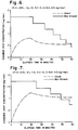
- Figure 5 illustrates the theoretical concentration of vapor phase hydrogen peroxide in a 145 cubic foot flexible film enclosure. A high injection rate for the first four minutes quickly brings the enclosure up to a concentration of 1 mg/liter. A lower injection rate for the next 26 minutes maintains the sterilant concentration in spite of degradation of the hydrogen peroxide vapor into water and oxygen at the assumed half life of five minutes.
- the cycle illustrated in Figure 5 was successfully run under the conditions shown. Biological indicators present in the enclosure demonstrated that sterilization was complete. No condensation of vapors occurred.
Abstract
Description
- The present invention relates to sterilization systems, and more particularly, to a circuit for recirculating, filtering and controlling the vapor content of the gaseous medium in a sealable enclosure.
- Conventional gaseous sterilization systems typically flow sterilant into the sterilization chamber and exhaust the sterilant to a drain. An open system is described in Picard et al. U.S. Patent No. 4,435,194. A problem often associated with such open systems is the safe disposal of residual gases. An open flow-through sterilization system that eliminates the problem of residual vapors is described in European patent application publication No, 0 298 694. One means of providing a closed system is taught in that European patent application, but that means does not address the problem of moisture build up in the system to be described below.
- Several closed systems for steam sterilizers have been developed which recirculate the steam rather than exhausting it. Arrangements for steam autoclaves are disclosed in Linder U.S. Patents Nos. 3,443,884 and 3,773,466. Another closed steam sterilization system is described in Childers U.S. Patent No. 4,808,377. In the closed steam sterilization systems, the steam is passed from the sterilization chamber, condensed, passed to a liquid storage compartment and eventually directed to a heater for conversion to steam and reuse in the sterilization chamber.
- When the sterilant is steam, moisture in the closed system is not a problem. It is simply recycled for further use in the sterilization process. If other gases were to be used as the sterilant in a closed system, e.g., ethylene oxide, vapor phase hydrogen peroxide or ozone, the buildup of moisture would be highly detrimental to the sterilization process.
- When the sterilant of choice is vapor phase hydrogen peroxide, which is typically generated from an aqueous solution of liquid hydrogen peroxide, the natural tendency of hydrogen peroxide vapor to degrade to oxygen and water would exacerbate the problem of moisture buildup in a closed system. The elimination of the need to dispose of residual sterilant vapors, however, commends a closed system for vapor phase hydrogen peroxide sterilization.
- An object of the present invention is to provide a closed gaseous sterilization system in which the moisture content of the gases can be controlled. A further object of the present invention is to provide such a system which can be used to sterilize a variety of existing enclosures. Finally, it is an object of the present invention to eliminate problems associated with the disposal of residual sterilant vapors.
- According to the present invention there is provided a method of conditioning and decontaminating the interior of a sealable enclosure and the contents thereof comprising:
- providing a sealable enclosure and processing means associated therewith;
- sealing said enclosure from fluid communication with unfiltered atmospheric air;
- filtering a gas and establishing a continuous recirculating flow of said filtered gas through said enclosure and through said means for processing said flow of filtered gas as fluidly connected to said enclosure and selectively sealed from fluid communication with unfiltered atmospheric air, wherein said processing means comprises a means for drying said flow of filtered gas, a means for heating said flow of filtered gas and conduit means fluidly connecting said drying means to said heating means;
- reducing the relative humidity of said gas within said recirculating flow of gas to a predetermined level by directing said flow of filtered gas through said drying means;
- selectively introducing a vapor decontaminant at a predetermined concentration into said flow of recirculating gas after said flow of filtered gas exits said drying means and before said flow of filtered gas enters said enclosure so that said flow of recirculating filtered gas carries said vapor decontaminant into and through said enclosure, wherein said vapor is a multicompound vapor and one component is water vapor;
- maintaining said continuous recirculating flow of filtered gas and vapor decontaminant through said enclosure for a first predetermined period of time sufficient for decontaminating said enclosure and any contents therein;
- continuously reducing the relative humidity of said recirculating flow of filtered gas to maintain the relative humidity at about said predetermined level for at least during said first period of time; and
- following said first period of time, discontinuing introduction of vapor decontaminant and continuing said flow of filtered gas into and through said enclosure for a second period of time sufficient for removing vapor decontaminant from said enclosure.
- The objects of the present invention are satisfied by the method of decontaminating a sealable enclosure and the contents thereof which includes the steps of sealing the enclosure from fluid communication with atmospheric air and establishing a continuous recirculating flow of a filtered gas, preferably air or nitrogen, through the enclosure and through a means fluidly connected to the enclosure for processing the flow of gas. The processing means is selectively sealed from fluid communication with atmospheric air. The method also includes the steps of reducing the relative humidity of the gas within the flow of recirculating gas to a predetermined level, selectively introducing a vapor decontaminant, preferably vapor phase hydrogen peroxide, into the flow of recirculating gas at a predetermined concentration so that the flow of recirculating gas carries the vapor decontaminant into and through the enclosure and maintaining the continuous flow of recirculating gas and vapor decontaminant through the enclosure for a first predetermined period of time. The first period of time may be that sufficient for sterilizing the enclosure and its contents or may be a period of time sufficient for disinfecting or sanitizing the enclosure and its contents. The relative humidity of the recirculating flow of gas is continuously reduced to about the predetermined level for at least during the first period of time. Following the first period of time, the method further includes the steps of continuing the flow of recirculating gas into and through the enclosure for a second period of time sufficient for removing residual vapor decontaminant from the enclosure. The vapor may be removed by converting the residual vapor decontaminant to a form suitable for disposal. Alternatively, or in addition, the vapor may be removed by physically removing it from the flow of gas.
- The method may also include the step of pressurizing the enclosure to a selected elevated level by selectively admitting filtered gas to the processing means or the step of evacuating the enclosure to a selected reduced level by selectively exhausting filtered gas from the processing means.
- The relative humidity of the gas is reduced preferably by circulating the flow of gas, or the flow of gas and vapor decontaminant, through a drying agent.
- The step of introducing vapor decontaminant into the recirculating flow of gas preferably comprises the steps of passing a liquid decontaminant to a vaporization chamber or some other means for heating the liquid decontaminant to a temperature sufficient for transforming the liquid into vapor and passing the flow of recirculating gas through the vaporization chamber, or heating means, to carry the vapor decontaminant into and through the enclosure. The vapor decontaminant may be introduced into the recirculating flow of gas in continuous increments or in intermittent increments.
- Following the second period of time, when the residual vapor decontaminant is removed from the enclosure, water vapor may be optionally introduced into the recirculating flow of gas to humidify the enclosure. When the water vapor is introduced, the circulating flow of gas bypasses the drying agent so that the relative humidity of the gas is not reduced. The step of introducing water vapor into the recirculating flow of gas comprises the steps of passing liquid water to a vaporization chamber or some other means of heating the liquid water to a temperature sufficient for transforming the liquid water to water vapor and passing the recirculating flow of gas through the vaporization chamber, or heating means, to carry the water vapor into and through the enclosure.
- The method of the present invention can be practiced in a sealable enclosure which is connected in a sealed relationship to a means for processing a gaseous medium. The processing means is preferably a unit for generating vapor decontaminant and recirculating and controlling the vapor and the humidity of the gaseous medium. The enclosure and the processing means establish a closed circuit for recirculating, decontaminating and controlling the vapor content of a gaseous medium in the enclosure. The means for processing the gaseous medium includes an inlet port connected to an outlet of the enclosure and at least one outlet port connected to corresponding inlets of the enclosure. The processing means includes a circuit proceeding from the inlet of the processing means through a first filter and through a pump for withdrawing the gaseous medium from the enclosure and for pushing the gaseous medium flowing down stream of the pump through a drying agent. The circuit also includes, downstream of the drying agent, at least one and preferably two, means for converting a selected decontaminant into a form suitable for disposal. The circuit proceeds from the converting means to a vaporizer and from the vaporizer to at least one outlet of the processing means. When the outlet port of the processing means is connected to the inlet of the enclosure, the circuit is extended to the enclosure and returns via the outlet of the enclosure to the inlet port of the processing means, when connected, to define the closed circuit.
- The processing means also includes at least one liquid reservoir fluidly connected to the vaporizer. An injection pump may be provided to aid in directing the liquid in the reservoir to the vaporizer. At least one liquid reservoir contains a liquid decontaminant, such as an aqueous solution of hydrogen peroxide. A second liquid reservoir, if present, may contain water to humidify the enclosure. First valve means are provided for selectively delivering liquid from the reservoir to at least one heating means.
- A second valve means is provided to selectively admit gas through the first filter to the closed circuit to increase the pressure therein. A third valve means and a second filter are provided to selectively exhaust gas through the second filter from the closed circuit to decrease the pressure therein. A fourth valve means and a bypass line are provided to permit the circuit to bypass the drying agent and proceed directly from the pump to the converting means when humidification is desired.
- The present invention can be better understood by reference to the drawings in which:
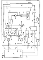
- Figure 1 is a schematic diagram of a preferred embodiment of the recirculation/drying unit of the present invention;
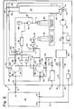
- Figure 2 is a schematic diagram of an alternative embodiment of the recirculation/drying unit of the present invention;
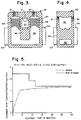
- Figure 3 is a section view of the vaporizer/converter used in the preferred embodiment of the recirculation/sterilization unit of the present invention;
- Figure 4 is a section view of the vaporizer/converter of Figure 3 along the line III-III;
- Figure 5 is a graph showing the theoretical concentration of vapor phase hydrogen peroxide in a 145 cubic foot flexible chamber for a recirculating airflow of 10.5 SCFM; and
- Figures 6 and 7 are graphs showing the theoretical concentration of vapor phase hydrogen peroxide having a half-life of ten and five minutes, respectively, in a 728 cubic foot rigid walled room for a recirculating air flow of 11 SCFM.
- Figures 1 and 2 illustrate the preferred embodiments of the recirculation/drying
unit 10 of the present invention. Theunit 10 is designed for use with almost anysealable enclosure 12. Theunit 10 provides a means and a method fordecontaminanting enclosure 12 and for recirculating, filtering and controlling the water and decontaminant vapor content of the gaseous medium within theenclosure 12 andunit 10. Theunit 10 can humidify or dehumidify, introduce decontaminant vapor into or remove it from the gaseous medium ofenclosure 12 as the gaseous medium moves through the closed circuit created whenunit 10 andenclosure 12 are connected. - The term "decontamination" and variations thereof as used herein shall mean the physical/chemical process (or product) by which an object, contaminated with harmful microbial life, is made safe for handling. The levels of decontamination are sterilization, disinfection and sanitization.
- The
unit 10 may be a self-contained, detachable unit which can be moved from enclosure to enclosure. Alternatively, theunit 10 may be integrally connected to a singlesealable enclosure 12. Thesealable enclosure 12 can be an enclosure having rigid walls, such as a clean room, a glove box, fume hood, biological safety cabinet, incubator or refrigerator, or an enclosure having flexible walls, such as a flexible film isolator. Theunit 10 can be used regardless of the internal pressure requirements of the enclosure.Unit 10 can be used to decontaminate the interiors and contents of negative pressure enclosures such as those used in virology, positive pressure enclosures, such as clean rooms and enclosures wherein there is no differential in pressure between the interior and the exterior of the enclosure. - Recirculation/drying
unit 10 includes generally anair pump 20, a drier 40, a reservoir ofliquid decontaminant 60, at least one, but preferably two vaporizer/converters fluid injection pump 90 and filters 30, 50 and 70. Valves, sensors and fluid flow lines are also provided. - The decontaminant is preferably vapor phase hydrogen peroxide. Other low temperature chemical decontaminants may be used. For reasons to be explained hereinbelow, steam is not recommended as the decontaminant in the
unit 10 of the present invention. - The
unit 10 uses air or some other nonhazardous gaseous medium, such as nitrogen, to circulate the decontaminant through theenclosure 12. For purposes of describing the preferred embodiments of the invention and without limiting the invention, the gaseous medium discussed will be air and the decontaminant discussed will be vapor phase hydrogen peroxide. The process discussed will assume that the objective is to sterilize theenclosure 12 and its contents. - Referring to Figure 1, the
enclosure 12 has two inlets, 14 and 16, and anoutlet 18. At least one inlet, 14 or 16 is required. Any suitable know means (not shown), such as a fan, may be provided to create turbulence in theenclosure 12 to mix the vapor sterilant throughout the enclosure. The recirculation/dryingunit 10 includes oneinlet port 22 and two outlet ports, 24 and 26. At least one outlet port, 24 or 26 is required.Inlets enclosure 12 are connected tooutlet ports unit 10 byfluid flow lines 21 and 23.Outlet 18 ofenclosure 12 is connected toinlet port 22 ofunit 10 byfluid flow line 25. By suitable known connections,inlets outlet 18 may be releasably or integrally connected in a sealed relationship to their respectivefluid flow lines outlet ports inlet port 22. Apressure sensor 28 located withinunit 10 is operatively connected vialine 27 to port 29 ofenclosure 12 to detect the level of pressure withinenclosure 12. - The fluid flow path through
unit 10 proceeds throughinlet port 22 alongreturn line 32 to anabsolute air filter 30, through aflow restricter 34, to pump 20 and to drier 40. Asensor 36 monitors the rate of flow through theflow restricter 34.Pump 20 pulls the air and the vapors withinenclosure 12 intounit 10, then pushes the air and vapors through drier 40. - Drier 40 may be any suitable known dessicant column. Molecular sieves known for their selective absortion characteristics may be used in the column. Anhydrous calcium sulfate sold by W. A. Hammand Drierite Company under the name DRIERITE, for example, is a neutral, chemically stable noncorrosive, nondisintegrating, nonpoisonous, regenerative drying agent which is inert to everything except water. The best drying agents are those that react rapidly and irreversibly with water. Some drying agents are soluble in solvents and can be explosive if mishandled. Care should be taken, therefore, to carefully choose a drying agent suitable for the circumstances in which it will be used.
- The drier 40 removes water from the gaseous medium as it passes through. Drier 40 is provided with an
electric heater 42. The drying agent is regenerated by passing a stream of heated air through it in a suitable known manner, between runs of the recirculation/dryingunit 10. Dessicants typically do not work or do not work well at high temperatures. Anhydrous calcium sulfate for example, works well at 75°F, but can work with only some loss of efficiency with a temperature rise up to 200°F. Theunit 10, therefore, is not suitable for steam sterilization processes or any other sterilization process wherein the temperature would be greater than the temperature tolerated by the particular drying agent used. - There are two exit paths from drier 40,
path 44 andpath 46.Path 44 leads toentrance port 81 in vaporizer/converter 80. Air fromline 44 passes intoport 81 of the converter portion of vaporizer/converter 80. Air fromline 46 passes intoport 83 of the converter portion of vaporizer/converter 82.Path 46 leads toentrance port 83 in vaporizer/converter 82. - The vaporizer and converter may be two separate units appropriately connected within
unit 10. In the preferred embodiment shown in Figures 3 and 4, however, they are used together as a single unit. The vaporizer/converter 80 is described and claimed in European patent application publication No. 0 298 694, referenced above, the disclosure of which is hereby incorporated herein by reference. Vaporizer/converter 80 has anexternal housing 84 and aninternal housing 86. Anouter chamber 88 is defined therebetween. Theinternal housing 86 defines aninner chamber 85. Theouter chamber 88, which functions as the converter, houses a plurality ofspheres 108 which define a low flow-resistant tortuous path having a high surface area for degradation of the sterilant. When the system is used as a hydrogen peroxide sterilization system, themetallic spheres 108 are preferably coated, or made entirely of, copper, platinum, palladium or some other material known to catalytically degrade hydrogen peroxide. Aheating element 104, such as an electric band heater, provides temperatures sufficiently high within theouter chamber 88, which, when coupled with the highly catalytic, high surface area tortuous pathway created byspheres 108, nearly instantaneously catalytically decomposes the sterilant vapor. Although thespheres 108 have been demonstrated to work well in decomposing hydrogen peroxide into its degradation products, water and oxygen, any suitable environment which substantially, and preferably completely, converts the sterilant to a form suitable for disposal will suffice. - The previously dried and now heated air exits the converter through
port 87 in vaporizer/converter 80 andport 89 in vaporiser/converter 82, and proceeds alonglines ports converter Path 92 splits after exiting fromport 89 toline 48 which leads tosolenoid valve 72,air filter 70 and vacuum bleed-outport 74.Solenoid valve 72 is opened to reduce the pressure within theunit 10 andenclosure 12 when the pressure exceeds a predetermined level.Valve 72 may be opened to reduce pressure by discharging filtered, dried air at timed intervals during a sterilization cycle if the cycle requires a reduction in pressure at a certain stage. - Pressure in
unit 10 andenclosure 12 can be increased by openingsolenoid valve 78 to admit outside air throughport 76 to pressure bleed-inline 75. Air admitted throughvalve 78 is pulled throughair filter 30 bypump 20 and directed to drier 40. Thesolenoid valve 78 can be opened at predetermined intervals in a sterilization cycle when increased pressure is desirable and can be opened to admit air if the pressure within theunit 10 andenclosure 12 drops below a predetermined desirable level. If theunit 10 is to be used in an explosion proof environment,port 76 can be connected to a slightly pressurized air supply from an external source. The pressurized gas can be used to purge theunit 10 andenclosure 12 before theunit 10 is energized. - At this point, the air can proceed through
vaporizer exit ports unit 10outlet ports lines 21 and 23 and intoenclosure 12 throughinlets Enclosure 12 is sealed except for the opening throughoutlet 18 alongline 25 toinlet port 22 ofunit 10 and the opening throughinlets outlet ports enclosure 12 in a continuous flowing manner. The continuous flow of recirculating air along the closed circuit just described can be used to aerate theenclosure 12 and dehumidify and filter the air by passing all of the air within the system throughfilter 30, drier 40 and vaporizer/converter - When a sterilization cycle is desired, the recirculating flow of air carries the sterilant vapor from the vaporizer into and through
enclosure 12 and returns it tounit 10 along the circuit just described. - Liquid hydrogen peroxide is supplied by
reservoir 60. Two three-way valves, 100 and 102, a ventedfilter 50 or anaccumulator 55 andfilter 57, aninjection pump 90 and pressure switches 52 and 54 are provided. Each three-way valve valves reservoir 60, throughinjection pump 90 and ventedfilter 50 where it is split between two lines; one leading to path C → A invalve 100 and one leading to path C → A invalve 102. The liquid sterilant proceeds toports converters - Heat from
heater 104 and, to some extent, the heat given off during the decomposition of the sterilant, is conducted through thespheres 108 andinternal housing 86 toinner chamber 85, which functions as the vaporizer to instantaneously vaporize the liquid sterilant when it enters theinner chamber 85 of vaporizer/converter 80. The vaporizer temperature when used for hydrogen peroxide sterilization is about 60-150°C (140-302°F). The vapor is then passed throughports converters outlet ports unit 10, alonglines 21 and 23 toinlets enclosure 12. The vapor may pass into theenclosure 12 continually or may pass incrementally as disclosed in Bier U.S. Patent No. 4,642,165, the relevant portions of which are hereby incorporated herein by reference. The control of the liquid injection is by an electronically controlled pressure compensated flow control that preferably produces a nearly continuous fine mist varying from 0.2 to 18 grams per minute. - The sterilant vapor, as stated above, is carried by the heated flowing air through the sealed enclosure. When the sterilant vapor returns to
unit 10 it passes throughfilter 30 and drier 40. Because the liquid sterilant is an aqueous solution of hydrogen peroxide, a portion of the vapor passed toenclosure 12 is water vapor. The hydrogen peroxide vapors are also degraded to some extent to oxygen and water. The water vapor portion of the degraded sterilant and the water vapor generated from vaporization of the liquid sterilant are substantially absorbed by the drying agent in drier 40. Low humidity air containing some sterilant exits drier 40 alonglines converters enclosure 12 and returned tounit 10 as described. The sterilization cycle is continued for as long as it takes to sterilizeenclosure 12. A shorter period can be used if only disinfection is desired. The flow of sterilant vapor through the flow lines and filters ofunit 10 ensures that these components are also sterilized. - When path C → B of three-
way divertor valve 100 is opened, the lines containing liquid hydrogen peroxide are directed back toreservoir 60. Since theliquid pump 90 will not permit back flow, this flow path from C → B prevents pressure buildup in the sterilant delivery lines when the hydrogen peroxide breaks down into water and oxygen. -
Unit 10 is primarily intended for humidity reduction, sterilization and aeration. However, if humidification is desired, the alternative embodiment illustrated in Figure 2 can be employed. Awater reservoir 62,injection pump 64 andfilter 66 are fluidly connected via path B → A through three-way valve 102 to port 98 of vaporizer/converter 82. - A three-way by-
pass valve 110 is provided in the line betweenpump 20 and drier 40. Path A → C ofvalve 110 directs flow into drier 40 as described above. Path A → B ofvalve 110 directs the flow of air around drier 40 along path 112 to joinpaths points - When humidification is desired,
valve 100 is energized C → A butinjection pump 90 is not activated. Path B → A ofvalve 102 is opened and injection pump 64 is activated. Path A → B ofvalve 110 is opened. Water is drawn fromreservoir 62 throughinjection pump 64 andfilter 66, along path B A ofvalve 102 to port 98 of the vaporizer portion of vaporizer/converter 82 as well as along path C → Avalve 100 to port 96 of vaporizer/converter 80. The water is vaporized in the vaporizer and passed intoenclosure 12 throughports outlet ports lines 21 and 23 andinlets converters - The moist air is drawn through
enclosure 12, exitsoutlet 18 and proceeds alongpath 25 toinlet port 22 and returnline 32, throughfilter 30 andpump 20.Pump 20 then pushes the stream of moist air through path A → B of by-pass valve 110, along path 112 topaths converters lines converters converter ports outlet ports inlets enclosure 12. That flow pattern is continued until humidification ofenclosure 12 is no longer desired. - When aeration alone is desired,
valves - In order to regenerate the circuit, the connections between
enclosure 12 andunit 10 atinlets outlet 18 are released to create an open circuit.Pump 20 draws in air throughfilter 30 at a predetermined controlled flow rate and passes it through drier 40.Heater 42 is activated so that this stream of air is heated and thereby removes moisture from the dessicant or molecular sieve material. Suitable known temperature sensors (not shown) in the drier can control regeneration by known means and can determine when regeneration is complete. Any residual sterilant vapor driven off by the regenerating drier 40 is converted to a form suitable for disposal in the converter portions of vaporizer/converters outlet ports - The recirculation/drying
unit 10 of the present invention provides a closed circuit when sealably connected toenclosure 12. It is easier and less expensive to dry the gaseous medium within a room, for example, by means of the closed recirculating circuit of the present invention than to purge the room using a dried gaseous medium. The predried air which results from the present invention will accept more of the preferred sterilant, a 30% by weight aqueous solution of hydrogen peroxide. As the relative humidity of the air withinenclosure 12 increases, the amount of vapor phase hydrogen peroxide that can be added without risking over saturation and condensation of the vapor decreases. - Table 1 contains a tabulation of the maximum allowable hydrogen peroxide vapor concentration as a function of the initial relative humidity and temperature, assuming the vaporization of a 30% by weight aqueous solution of hydrogen peroxide. Condensation of the sterilant vapor will not occur when the recommended concentrations in Table 1 are not exceeded.
TABLE I Temperature Concentration °F *Maximum Allowable H2O2 Vapor RH=0% RH=10% RH=40% RH=80% 50 0.750 0.626 0.325 0.081 59 1.061 0.889 0.467 0.117 68 1.481 1.241 0.661 0.166 77 2.043 1.720 0.913 0.224 *Assuming vaporization of 30% by weight aqueous solution of H2O2. - In order to avoid condensation of the sterilant, it is important to reduce the relative humidity in an enclosure prior to introduction of the sterilant vapor. For example, to reduce the relative humidity in a 1000 cubic foot enclosure at 68°F from 40% to 10%, 151.8 grams of moisture must be removed in a recirculation system. In an open system (i.e., flowing mixer), in order to reduce the relative humidity in the enclosure from 40% to about 6%, three times the amount of air and moisture would have to be flushed through the enclosure. This would require an air drier that is 3 times larger.
- Another advantage to a closed recirculating circuit is that less pressure or vacuum is applied to the enclosure as compared to an open circuit. In an open system, a pressure differential must be created which is sufficient to push or pull the gaseous medium through the supply piping, enclosure and exhaust piping. In the recirculating closed circuit, the enclosure acts like "piping" which connects the inlet of a pump to the pumps own outlet. The pressure drop in this piping is negligibly small since the gaseous medium is exiting at the same rate it is entering, and the effective "piping" diameter is the cross-section of the chamber. The pump does not have to be concerned with the absolute pressure of the enclosure because it is pumping "from" and "to" the same pressure. A smaller, less powerful pump can be employed. The recirculating closed circuit of the present invention does not exhaust residual sterilant vapors into the atmosphere. The vapors are returned to the
unit 10 from theenclosure 12, dried and decomposed into harmless components which can be recirculated to theenclosure 12 while the system is in operation. Any exhaust to atmosphere during or after the use of the system is through a filter and occurs only after the residual vapors have been decomposed. - A preferred method for employing the recirculation/drying
unit 10 of the present invention includes a conditioning phase in which pump 20 is energized to draw the air fromenclosure 12 and circulate it throughunit 10 to dry and heat it, preferably until the relative humidity ofenclosure 12 is reduced to about 10% or less. The air flow rate in the system of the present invention can be from 4-12 SCFM. At that point,valve 100 can be opened to permit liquid sterilant to be metered to the vaporizer portions of vaporizer/converters enclosure 12 as described above. The introduction of vapor phase hydrogen peroxide can be in continuous increments or in intermittent increments at timed intervals depending upon the sterilization cycle to be employed for a particular type of enclosure. - If the sterilization cycle of choice includes evacuation stages or pressurization stages,
valves enclosure 12. The introduction of sterilant proceeds for a period of time sufficient for sterilizingenclosure 12 and the contents thereof. Alternatively, the introduction can proceed for a period of time sufficient for disinfectingenclosure 12 and it contents. Thereafter,valve 100 is closed and liquid sterilant injection into the vaporizers ceases. - Following the sterilization phase, the recirculation, filtering and drying of the gaseous medium continues in the aeration phase to ensure removal of the sterilant from
enclosure 12 and the piping ofunit 10. The flow of the gaseous medium through drier 40 and the converters removes any residual sterilant, converting it to a form suitable for disposal. In the case of hydrogen peroxide, the residuals are converted to the harmless degradation products, water and oxygen. When the residuals have been lowered to a desired level, pump 20 can be turned off. Alternatively, a desired positive or negative pressure can be maintained inenclosure 12. - If desired,
enclosure 12 can be humidified to return it to the level of relative humidity present prior to the conditioning phase.Pump 20 would remain energized,valve 102 would be opened and pump 64 would be energized to deliver increments of water to the vaporizer. The resulting water vapor is then carried by the flow of air or drawn intoenclosure 12. By-pass valve 110 would be activated to divert the flow of moist air away from drier 40 directly to the converters. - Following completion of the conditioning, sterilization, aeration and optional humidification phases, the
unit 10 can be disconnected fromenclosure 12 to permit regeneration of the drying agent as described above. - Figure 5 illustrates the theoretical concentration of vapor phase hydrogen peroxide in a 145 cubic foot flexible film enclosure. A high injection rate for the first four minutes quickly brings the enclosure up to a concentration of 1 mg/liter. A lower injection rate for the next 26 minutes maintains the sterilant concentration in spite of degradation of the hydrogen peroxide vapor into water and oxygen at the assumed half life of five minutes. The cycle illustrated in Figure 5 was successfully run under the conditions shown. Biological indicators present in the enclosure demonstrated that sterilization was complete. No condensation of vapors occurred.
- Figures 6 and 7 illustrate the theoretical concentration of vapor phase hydrogen peroxide for a 6.5 x 8.0 x 14 cubic foot rigid walled room, assuming an air circulation rate of 11 SCFM. The stepped graph above the concentration indicates the maximum allowable vapor phase hydrogen peroxide concentration at the given conditions. If the graphs were to cross, condensation would occur. The initial relative humidity was reduced to less than 10% before the introduction of sterilant vapor.
- A theoretical computer generated run was made to determine how long it would take for an enclosure with 10 air exchanges per hour to be reduced from 100% relative humidity to 10% relative humidity in a flowing mixer. It took 97.7 minutes to reduce a 1869 liter enclosure by passing totally dry air through it in a flowing mixer situation.
- A run was then made using the same program with different variables to see how it would take to aerate the same enclosure to 1 PPM (1 mg/liter = approximately 720 PPM). It took 220 minutes for the enclosure to go from 3.56 mg/liter (2563 PPM) to .0198 mg/liter (14.3 PPM).
- During flow through in an open circuit the air has to have 22.778 mg/liter of moisture removed to reduce its relative humidity from 100% to 10% during all phases of the cycle. During the conditioning phase of the method of the present invention, 22.778 mg/liter must be removed from the 1869 liter enclosure. During the sterilization and aeration phases of the method of the present invention, no more than the total amount of sterilant injected must be removed.
- A comparison was made of the open and closed circuit methods of the air drying requirements for a 30 minute sterilization cycle on the 1869 liter enclosure with an air flow of 31.15 liter/min. assuming 100% humidity at 80°F.:
TABLE II Phase of Cycle Elapsed Time Moisture Absorbed by Air Dryer Recirc/Dry Closed Circuit Flow Through Open Circuit Condition 97.7 min 42.6 grams 69.3 grams Sterilize 60 min 30.7 grams 21.3 grams Aerate 220 min 156.1 grams Total 337.7 min 73.3 grams 246.7 grams - There is more than a 3:1 difference in the drying requirements of the two systems. The comparison assumed 100% dry air was used to dilute the room during the condition phase of the open circuit flow through method. In reality, only 90% dry air was available. The aeration was ended when 14 PPM moisture remained in the enclosure instead of 1 PPM. It would have further extended the aeration time and increased the drying requirements of the flow through system if the run proceeded until 1 PPM moisture was achieved.
- The recirculation/drying
unit 10 of the present invention eliminates moisture build up as a problem and thus, is able to maintain the enclosures to be sterilized at higher concentrations of vapor phase hydrogen peroxide for longer periods of time when compared to a recirculating system which does not include drier 40. In such a system, moisture would build up to intolerable levels. Moisture build up is not present in open flow through systems which can exhaust the moist air, but unacceptable amounts of residual sterilant are exhausted with the moist air. The recirculation/dryingunit 10 of the present invention has the advantages of the open systems in its ability to maintain sterilant concentration for extended time periods and the advantages of the closed systems in its ability to avoid the introduction of residual sterilant vapors into the atmosphere. Yet, this invention can use a smaller air drier system because the most moisture it ever has to absorb is that initially contained in the gaseous medium within the enclosure plus that injected. A flow through system could have to absorb 3 times that amount of moisture.
Claims (25)
- A method of conditioning and decontaminating the interior of a sealable enclosure and the contents thereof comprising:providing a sealable enclosure and processing means associated therewith;sealing said enclosure from fluid communication with unfiltered atmospheric air;filtering a gas and establishing a continuous recirculating flow of said filtered gas through said enclosure and through said means for processing said flow of filtered gas as fluidly connected to said enclosure and selectively sealed from fluid communication with unfiltered atmospheric air, wherein said processing means comprises a means for drying said flow of filtered gas, a means for heating said flow of filtered gas and conduit means fluidly connecting said drying means to said heating means;reducing the relative humidity of said gas within said recirculating flow of gas to a predetermined level by directing said flow of filtered gas through said drying means;selectively introducing a vapor decontaminant at a predetermined concentration into said flow of recirculating gas after said flow of filtered gas exits said drying means and before said flow of filtered gas enters said enclosure so that said flow of recirculating filtered gas carries said vapor decontaminant into and through said enclosure, wherein said vapor is a multicompound vapor and one component is water vapor;maintaining said continuous recirculating flow of filtered gas and vapor decontaminant through said enclosure for a first predetermined period of time sufficient for decontaminating said enclosure and any contents therein;continuously reducing the relative humidity of said recirculating flow of filtered gas to maintain the relative humidity at about said predetermined level for at least during said first period of time; andfollowing said first period of time, discontinuing introduction of vapor decontaminant and continuing said flow of filtered gas into and through said enclosure for a second period of time sufficient for removing vapor decontaminant from said enclosure.
- The method of claim 1 further comprising selectively admitting additional filtered gas to said processing means to increase the pressure within said enclosure to a selected elevated level.
- The method of claim 1 further comprising selectively exhausting filtered gas from said processing means to reduce the pressure within said enclosure to a selected reduced level.
- The method of claim 1 wherein said step of reducing the relative humidity comprises circulating said flow of filtered gas through a drying agent.
- The method of claim 1 wherein the step of introducing a vapor decontaminant into said flow of filtered gas comprises passing a liquid decontaminant to a means for heating said liquid decontaminant to a temperature sufficient for substantially instantaneously transforming said liquid into vapor and passing said flow of filtered gas through said heating means to carry said vapor into and through said enclosure.
- The method of claim 1 wherein said first predetermined period of time is sufficient for sterilizing said enclosure and said contents.
- The method of claim 1 wherein said first predetermined period of time is sufficient for disinfecting said enclosure and said contents.
- The method of claim 1 wherein said first predetermined period of time is sufficient for sanitizing said enclosure and said contents.
- The method of claim 1 wherein said step of selectively introducing said vapor decontaminant comprises introducing said vapor decontaminant into said flow of filtered gas in continuous increments.
- The method of claim 1 wherein said step of selectively introducing said vapor decontaminant comprises introducing said vapor decontaminant into said flow of filtered gas in intermittent increments.
- The method of claim 1 further comprising heating said flow of filtered gas before said flow of gas enters said enclosure.
- The method of claim 1 further comprising creating turbulence in said enclosure to mix said vapor decontaminant throughout said enclosure.
- The method of claim 1 further comprising:following said second period of time introducing water vapor into said flow of filtered gas to humidify said enclosure; anddiscontinuing said step of maintaining the relative humidity of said gas at about said predetermined level.
- The method of claim 1 wherein said residual vapor decontaminant is removed from said enclosure by converting said residual vapor decontaminant to a form suitable for disposal.
- The method of claim 1 wherein said residual vapor decontaminant is removed from said enclosure by directing said residual vapor decontaminant out of said enclosure for storage and subsequent disposal.
- A method for recirculating, decontaminanting and controlling the vapor content of a gaseous medium in a sealable enclosure comprising:a. sealing said enclosure from communication with atmospheric air;b. withdrawing gas from said enclosure;c. passing the gas through a filter;d. directing the gas from said filter to a means for removing moisture from the gas;e. directing the gas from said moisture removing means to means for degrading a selected sterilant into degradation products suitable for disposal;f. directing the gas from said converting means to means for heating a liquid to a temperature sufficient for transforming the liquid into a vapor;g. directing the gas from said heating means to said enclosure;h. repeating steps b. through g. for a first period of time sufficient to reduce the relative humidity of the gas to a predetermined level;i. at the end of said first period of time, directing a liquid decontaminant from a liquid decontaminant reservoir to said heating means wherein said liquid decontaminant is transformed into a vapor decontaminant;j. introducing said vapor decontaminant into the gas flowing through said heating means and directing the gas and vapor decontaminant from said heating means to said enclosure;k. withdrawing gas and said vapor decontaminant from said enclosure;l. passing the gas and said vapor decontaminant through said filter;m. directing the gas and said vapor decontaminant from said filter to said moisture removing means;n. directing the gas and said vapor decontaminant from said moisture removing means to said converting means wherein said vapor decontaminant is transformed into its degradation products suitable for disposal;o. directing the gas and the degradation products from said converting means to said heating means;p. repeating steps i. through o. for a second predetermined period of time; andq. at the end of said second period of time, discontinuing step i. and j. and continuing steps k. through o. for a third period of time sufficient for removing residual vapor decontaminant from said enclosure and the gas flow and for transforming said residual decontaminant in to its degradation products.
- The method recited in claim 16 further comprising:r. at the end of said third period of time, directing water from a water reservoir to said heating means wherein the water is transformed into water vapor;s. introducing said water vapor into the gas flowing through said heating means and directing the gas and said water vapor from said heating means to said enclosure;t. withdrawing gas and said water vapor from said enclosure;u. passing the gas and said water vapor through said filter;v. diverting the gas and the water vapor away from said moisture removing means and directly to said converting means;w. directing the gas and said water vapor from said converting means to said heating means; andx. repeating steps r. through w. for a fourth period of time sufficient to humidify said enclosure.
- The method recited in claim 16 further comprising increasing the pressure in said enclosure to a desired elevated level by selectively introducing additional gas through said filter into the flow of gas directed from said filter to said moisture removing means.
- The method recited in claim 16 further comprising decreasing the pressure in said enclosure to a desired reduced level by selectively exhausting gas through a second filter from said moisture removing means.
- A means for recirculating the gaseous medium within a sealable enclosure and of generating and controlling the vapor content of the gaseous medium within said sealable enclosure, said sealable enclosure having at least one inlet and an outlet comprising:an inlet port;means for fluidly connecting said inlet port to said outlet of said enclosure in a sealed relationship;at least one outlet port;means for fluidly connecting each said at least one outlet port to a corresponding one of said at least one inlet of said enclosure;a circuit proceeding from said inlet port to said at least one outlet port;a first filter in said circuit down stream of said inlet port;a pump in said circuit downstream of said first filter for withdrawing the gaseous medium from said enclosure;a drying agent in said circuit downstream of said pump;at least one means in said circuit downstream of said drying agent for converting a selected decontaminant into a form suitable for disposal;at least one means in said circuit downstream of said at least one converting means for heating a liquid to a temperature sufficient for transforming the liquid into a vapor, said at least one heating means being immediately upstream of said at least one outlet port;at least one liquid reservoir; andfirst valve means for selectively delivering liquid from said at least one liquid reservoir to said at least one heating means.
- The recirculating, generating and controlling means recited in claim 20 further comprising a second valve means to selectively admit gas through said first filter to said circuit to increase the pressure in said enclosure when said inlet port and said at least one outlet port are fluidly connected, respectively, to said outlet and said corresponding one of said at least one inlet of said enclosure.
- The recirculating, generating and controlling means recited in claim 20 further comprising a third valve means and a second filter to selectively exhaust gas from said circuit through said second filter to decrease the pressure in said enclosure when said inlet port and said at least one outlet port are fluidly connected, respectively, to said outlet and said corresponding one of said at least one inlet of said enclosure.
- The recirculating, generating and controlling means recited in claim 20 further comprising:means positioned in said circuit between said first filter and said pump to control the rate of flow of gas through said circuit.
- The recirculating, generating and controlling means recited in claim 20 further comprising:a by-pass line leading to said at least one converting means;a fourth valve means in said circuit between said pump and said drying agent and fluidly connected to said by-pass line to selectively direct the flow of gas in said circuit to said drying agent or to said by-pass line.
- The recirculating, generating and controlling means recited in claim 20 wherein said at least one outlet port comprises two outlet ports, said at least one converting means comprises two converting means, said at least one heating means comprises two heating means and said at least one liquid reservoir comprises two liquid reservoirs.
Applications Claiming Priority (3)
| Application Number | Priority Date | Filing Date | Title |
|---|---|---|---|
| US07/419,993 US5173258A (en) | 1989-10-11 | 1989-10-11 | Recirculation, vapor and humidity control in a sealable enclosure |
| US419993 | 1989-10-11 | ||
| PCT/US1990/005792 WO1991005573A1 (en) | 1989-10-11 | 1990-10-10 | Recirculation, vapor and humidity control in a sealable enclosure |
Publications (2)
| Publication Number | Publication Date |
|---|---|
| EP0486623A1 EP0486623A1 (en) | 1992-05-27 |
| EP0486623B1 true EP0486623B1 (en) | 1997-01-08 |
Family
ID=23664620
Family Applications (1)
| Application Number | Title | Priority Date | Filing Date |
|---|---|---|---|
| EP90915666A Expired - Lifetime EP0486623B1 (en) | 1989-10-11 | 1990-10-10 | Recirculation, vapor and humidity control in a sealable enclosure |
Country Status (4)
| Country | Link |
|---|---|
| US (1) | US5173258A (en) |
| EP (1) | EP0486623B1 (en) |
| DE (1) | DE69029660T2 (en) |
| WO (1) | WO1991005573A1 (en) |
Cited By (5)
| Publication number | Priority date | Publication date | Assignee | Title |
|---|---|---|---|---|
| US7014813B1 (en) | 1999-09-21 | 2006-03-21 | Bioquell Uk Limited | Methods and apparatus for vapor phase sterilisation |
| US7025932B2 (en) | 2000-03-21 | 2006-04-11 | Bioquell Uk Limited | Control of gaseous sterilization |
| US7186371B1 (en) | 1999-06-04 | 2007-03-06 | Bioquell Uk Limited. | Sealed enclosure sterilization |
| US9107973B1 (en) | 2014-04-09 | 2015-08-18 | dReiniger, LLC | Enclosure to disinfect lab coats and other textiles and objects of similar size to lab coats |
| FR3074049A1 (en) * | 2017-11-29 | 2019-05-31 | Airinspace | DEVICE FOR SURFACE DISINFECTION BY AIR |
Families Citing this family (87)
| Publication number | Priority date | Publication date | Assignee | Title |
|---|---|---|---|---|
| CA2146146C (en) * | 1992-10-01 | 2003-09-23 | Robert Warren Childers | Accumulator-based liquid metering system and method |
| US5713137A (en) * | 1995-05-17 | 1998-02-03 | Fujita; Sanai | Apparatus for deodorizing, sterilizing and drying bedding and clothing |
| US5711705A (en) * | 1995-05-25 | 1998-01-27 | Flanders Filters, Inc. | Isolation work station |
| US5906794A (en) * | 1995-06-15 | 1999-05-25 | American Sterilizer Company | Continuous-operation, closed loop decontamination system and method |
| US5872359A (en) * | 1995-07-27 | 1999-02-16 | American Sterilizer Company | Real-time monitor and control system and method for hydrogen peroxide vapor decontamination |
| AUPN545495A0 (en) * | 1995-09-14 | 1995-10-12 | Jacobs, David Ian | Air conditioning system |
| AU707583B2 (en) * | 1995-09-14 | 1999-07-15 | David Ian Jacobs | Air conditioning system |
| AU713190B2 (en) * | 1995-09-14 | 1999-11-25 | David Ian Jacobs | Air conditioning system |
| GB9523717D0 (en) * | 1995-11-20 | 1996-01-24 | Mdh Ltd | Method and apparatus for hydrogen peroxide vapour sterilization |
| US5876664A (en) * | 1996-06-14 | 1999-03-02 | American Sterilizer Company | Continuous-operation, closed loop decontamination system and method |
| US5961936A (en) * | 1996-12-12 | 1999-10-05 | Johnson & Johnson | Arrangement for adapting a gas generation and recovery system to a target volume |
| AU4761897A (en) * | 1996-12-12 | 1998-06-18 | Ethicon Inc. | Method and arrangement for controlling flow for decontaminating |
| US5779973A (en) * | 1997-04-01 | 1998-07-14 | Steris Corporation | Vapor phase interstitial microbial decontamination of overwrapped IV bags |
| GB2323785A (en) * | 1997-04-05 | 1998-10-07 | Medical Air Tech Ltd | Fumigation of microbiological safety cabinet |
| US5792435A (en) * | 1997-04-08 | 1998-08-11 | Steris Corporation | Vapor phase decontaminant isolator apparatus with integral vapor phase decontaminant generator system |
| US6077480A (en) * | 1997-06-19 | 2000-06-20 | Steris Corporation | Multiple flashpoint vaporization system |
| US6170166B1 (en) | 1998-07-10 | 2001-01-09 | Ecolab Inc. | Removal of heat and water vapor from commercial dishwashing machines |
| US7588720B2 (en) * | 1999-04-30 | 2009-09-15 | Tso3, Inc. | Method and apparatus for ozone sterilization |
| ES2154592B1 (en) * | 1999-05-27 | 2001-10-16 | Univ Politecnica De Cataluna | EQUIPMENT AND PROCEDURE FOR MASS DEACDIFICATION, ELIMINATION OF FREE ACIDITY AND DISINFESTATION OF CELLULOSICAL MATERIALS. |
| GB2367494A (en) * | 2000-08-04 | 2002-04-10 | Microflow Ltd | Sterilizing enclosures using sterilant vapours |
| US20050084415A1 (en) * | 2001-02-16 | 2005-04-21 | Steris, Inc. | High capacity flash vapor generation systems |
| WO2002092140A1 (en) | 2001-05-11 | 2002-11-21 | Steris Inc. | Non-dispersive mid-infrared sensor for vaporized hydrogen peroxide |
| US20030124026A1 (en) * | 2001-11-05 | 2003-07-03 | Hal Williams | Apparatus and process for concentrating a sterilant and sterilizing articles therewith |
| WO2004035094A2 (en) * | 2002-01-16 | 2004-04-29 | Steris Inc. | Flexible walk-in environmental enclosure |
| WO2003072150A1 (en) * | 2002-02-28 | 2003-09-04 | Steris, Inc. | Hydrogen peroxide vapor system with replaceable desiccant cartridge |
| US20060153766A1 (en) * | 2002-03-07 | 2006-07-13 | Iverson Carl E | Slow release production of chlorine dioxide from acidified sodium chlorite |
| ATE372136T1 (en) * | 2002-03-28 | 2007-09-15 | Bioquell Uk Ltd | METHOD AND DEVICE FOR DECONTAMINATION OF ENCLOSED SPACES |
| US6986654B2 (en) * | 2002-07-03 | 2006-01-17 | Therics, Inc. | Apparatus, systems and methods for use in three-dimensional printing |
| US7578969B2 (en) * | 2002-08-07 | 2009-08-25 | American Sterilizer Company | Decontamination system for mail and other articles |
| GB2393393B (en) * | 2002-09-24 | 2005-06-15 | Bioquell Uk Ltd | A pre-sterilisation ante-chamber for a processing enclosure |
| US20040146425A1 (en) * | 2003-01-24 | 2004-07-29 | Joshi Ashok V. | Deodorizer |
| ATE402721T1 (en) * | 2003-01-31 | 2008-08-15 | Steris Inc | BUILDING DECONTAMINATION WITH VAPOR HYDROGEN PEROXIDE |
| DE502004004812D1 (en) * | 2003-04-11 | 2007-10-11 | Dynamic Microsystems Semicondu | DEVICE AND METHOD FOR CLEANING AND DRYING OF OBJECTS USED IN THE MANUFACTURE OF SEMICONDUCTORS, IN PARTICULAR OF WAFER SHEET AND CLEANING CONTAINERS |
| US20040261820A1 (en) * | 2003-06-30 | 2004-12-30 | Monsrud Lee J. | Dishwashing machine having a water vapor recovery line and method for washing articles |
| US7186373B2 (en) | 2003-07-22 | 2007-03-06 | Steris Inc. | Visual detector for vaporized hydrogen peroxide |
| US7238330B2 (en) * | 2003-10-21 | 2007-07-03 | Steris Inc. | System and method for increasing concentration of sterilant in region |
| US20050129571A1 (en) * | 2003-12-10 | 2005-06-16 | Steris Inc. | Ozone enhanced vaporized hydrogen peroxide decontamination method and system |
| EP1778909B1 (en) * | 2004-08-18 | 2010-04-14 | LG Electronics Inc. | Controlling methof for automatically drying |
| US20060088441A1 (en) * | 2004-10-21 | 2006-04-27 | Steris Inc. | Vaporized hydrogen peroxide concentration detector |
| US20070023536A1 (en) * | 2005-06-13 | 2007-02-01 | Colin Baston | Methods and apparatus for optimizing environmental humidity |
| ITMI20051342A1 (en) * | 2005-07-14 | 2007-01-15 | W & H Sterilization Srl | VASPOR GENERATOR PERFECTED FOR AN AUTOCLAVE |
| JP5590797B2 (en) * | 2005-08-04 | 2014-09-17 | サバン ヴェンチャーズ ピーティーワイ リミテッド | Disinfection of space |
| US7850931B2 (en) * | 2005-08-11 | 2010-12-14 | American Sterilizer Company | Self-contained deactivation device |
| US20070098592A1 (en) * | 2005-11-01 | 2007-05-03 | Steris Inc. | Parallel flow VHP decontamination system |
| US8236240B2 (en) * | 2006-02-25 | 2012-08-07 | James Arthur Childers | Method and system for conducting vapor phase decontamination of sealable entities and their contents |
| JP4799221B2 (en) * | 2006-03-06 | 2011-10-26 | 三洋電機株式会社 | Incubator for isolator |
| NL2000064C2 (en) | 2006-04-28 | 2007-10-30 | Infection Control B V | Method and device for disinfecting a room. |
| EP2184074B9 (en) | 2006-05-01 | 2014-10-01 | American Sterilizer Company | Hydrogen peroxide vaporizer |
| US8513176B2 (en) | 2006-08-02 | 2013-08-20 | Ch2O Incorporated | Disinfecting and mineral deposit eliminating composition and methods |
| US7700056B2 (en) * | 2006-08-10 | 2010-04-20 | American Sterilizer Company | Modular decontamination system |
| US20080118419A1 (en) * | 2006-11-20 | 2008-05-22 | Efin Ya Lyublinski | Systems for decreasing environmental corrosion factors and/or for delivering one or more corrosion inhibiting compounds to an enclosure |
| US7578208B2 (en) * | 2006-12-15 | 2009-08-25 | Mocon, Inc. | System and method for generating a gas sample of known and adjustable relative humidity |
| US7919059B2 (en) * | 2007-04-27 | 2011-04-05 | American Sterilizer Company | Vaporized hydrogen peroxide decontamination system with concentration adjustment mode |
| US7640782B2 (en) * | 2007-04-27 | 2010-01-05 | American Sterilizer Company | Vaporized hydrogen peroxide probe calibration rig |
| GB0710331D0 (en) * | 2007-05-30 | 2007-07-11 | Bioquell Uk Ltd | Improved in or relating to methods of decontaminating enclosed spaces |
| US7850925B2 (en) * | 2007-06-15 | 2010-12-14 | American Sterilizer Company | Apparatus for removal of vaporized hydrogen peroxide from a region |
| WO2009008755A1 (en) * | 2007-07-10 | 2009-01-15 | Helder Da Costa Goncalves | Hydrogen peroxide sterilization process and device |
| US8007717B2 (en) * | 2007-08-14 | 2011-08-30 | American Sterilizer Company | Method and apparatus for decontaminating a region without dehumidification |
| US20090087921A1 (en) * | 2007-10-02 | 2009-04-02 | Steris Inc. | Vaporized hydrogen peroxide concentration detector |
| US7993587B2 (en) * | 2008-05-02 | 2011-08-09 | Mocon, Inc. | Humidity control system for the sensing cell of an analyte permeation testing instrument |
| WO2009138430A1 (en) * | 2008-05-13 | 2009-11-19 | Infection Control B.V. | Method and device for disinfecting a space |
| DE102008059854A1 (en) * | 2008-12-01 | 2010-06-02 | Thermo Electron Led Gmbh | Incubation and dry storage device |
| JP5485557B2 (en) * | 2009-01-26 | 2014-05-07 | パナソニックヘルスケア株式会社 | Isolator |
| EP2210618B8 (en) * | 2009-01-26 | 2013-06-26 | Panasonic Healthcare Co., Ltd. | Isolator |
| JP5603065B2 (en) * | 2009-01-30 | 2014-10-08 | パナソニックヘルスケア株式会社 | Sterile substance supply device and isolator |
| US8230616B2 (en) * | 2009-06-11 | 2012-07-31 | Sterilucent, Inc. | Apparatus and method for drying and sterilizing objects in a load |
| US8758681B2 (en) | 2009-07-28 | 2014-06-24 | Czeslaw Golkowski | Free radical sterilization system and method |
| US8221679B2 (en) * | 2009-07-28 | 2012-07-17 | Czeslaw Golkowski | Free radical sterilization system and method |
| USRE47582E1 (en) | 2009-07-28 | 2019-08-27 | Sterifre Medical, Inc. | Free radical sterilization system and method |
| EP2535650B1 (en) * | 2010-01-13 | 2016-12-14 | Metall + Plastic GmbH | Decontamination arrangement and method |
| US20120219456A1 (en) * | 2010-02-11 | 2012-08-30 | Esco Technologies Pte Ltd | Integrated Automatic Humidity Control And Decontamination System For Incubators And Other Laboratory Equipment |
| JP4977233B2 (en) * | 2010-05-24 | 2012-07-18 | 株式会社大気社 | Decontamination management method and decontamination management device used in the decontamination management method |
| JP5533312B2 (en) * | 2010-06-16 | 2014-06-25 | 澁谷工業株式会社 | Decontamination liquid supply device |
| GB2487379A (en) | 2011-01-18 | 2012-07-25 | Bioquell Uk Ltd | Control of decontamination cycles |
| US20120275953A1 (en) * | 2011-04-29 | 2012-11-01 | Robert Lukasik | Method for reducing the concentration of disinfectant, decontamination apparatuses and systems and related methods of employing the same |
| ITMI20111318A1 (en) * | 2011-07-15 | 2013-01-16 | Absolute Up S R L | AUTOCLAVE IN PARTICULAR FOR MEDICAL DENTAL USE |
| JP5754469B2 (en) * | 2011-10-06 | 2015-07-29 | キヤノンマーケティングジャパン株式会社 | Sterilizer, sterilization method, program |
| US9527594B2 (en) | 2012-04-24 | 2016-12-27 | Hamilton Sundstrand Corporation | Condenser with recirculation air mixer |
| US10710758B2 (en) * | 2017-07-12 | 2020-07-14 | Vanrx Pharmasystems Inc. | Apparatus and method for monitoring and controlling the removal of a cover from a sealed tub in an aseptic environment |
| EA033161B1 (en) | 2012-06-01 | 2019-09-30 | Новартис Аг | Syringe |
| JP6052499B2 (en) * | 2013-02-05 | 2016-12-27 | 株式会社大気社 | Decontamination method and decontamination system for performing the decontamination method |
| US9101208B2 (en) | 2013-03-15 | 2015-08-11 | Hussmann Corporation | Self cleaning refrigerated display case |
| US9801967B2 (en) | 2014-03-19 | 2017-10-31 | Steris Inc. | Saturation-enhanced, low-concentration vaporized hydrogen peroxide decontamination method |
| EP3471782A1 (en) * | 2016-06-17 | 2019-04-24 | Sterifre Medical Inc. | Sterilization, disinfection, sanitization, decontamination, and therapeutic devices, systems, and methods |
| US10918754B2 (en) * | 2017-03-27 | 2021-02-16 | Regeneron Pharmaceuticals, Inc. | Sterilisation method |
| EP3700584A4 (en) | 2017-10-25 | 2021-08-11 | Sterifre Medical, Inc. | Devices, systems, and methods for sterilization, disinfection, sanitization and decontamination |
| CN113774508B (en) * | 2021-09-15 | 2023-08-08 | 嘉兴市富达化学纤维厂 | Spinning method based on air bag leftover material regenerated nylon 66 fiber |
Family Cites Families (12)
| Publication number | Priority date | Publication date | Assignee | Title |
|---|---|---|---|---|
| DE1492381B1 (en) * | 1964-09-29 | 1970-07-23 | Linder Dr Fritz | Device on autoclaves and similar pressure-tight containers |
| US3620265A (en) * | 1970-07-09 | 1971-11-16 | Lif O Gen Inc | Method for sterilizing gas containers and filling same with a sterile gas |
| US3687612A (en) * | 1970-10-12 | 1972-08-29 | Sybron Corp | Method of controlling relative humidity in gaseous sterilizers |
| DE2745961A1 (en) * | 1977-10-12 | 1979-04-19 | Muenchner Medizin Mechanik | METHOD AND GAS STERILIZER FOR STERILIZING WITH THE HELP OF STERILIZING GAS |
| US4230571A (en) * | 1979-01-22 | 1980-10-28 | Dadd Robert C | Ozone/ultraviolet water purification |
| FR2475679A1 (en) * | 1980-02-12 | 1981-08-14 | Calhene | CIRCUIT FOR VENTILATION AND FILTRATION OF THE ENVIRONMENT CONTENT IN A SEALED ENCLOSURE |
| DE3523310A1 (en) * | 1985-06-29 | 1987-01-02 | Bayer Ag | Method of sterilising systems, apparatus and rooms with gaseous sterilising agents |
| FR2604627B1 (en) * | 1986-10-07 | 1988-12-23 | Mercey Gilles | STERILIZER |
| FR2613229B1 (en) * | 1987-03-30 | 1989-06-30 | Calhene | METHOD FOR STERILIZING A SEALED ENCLOSURE AND INSTALLATION FOR CARRYING OUT THIS METHOD |
| US4909999A (en) * | 1987-07-06 | 1990-03-20 | American Sterilizer Company | Flow-through vapor phase sterilization system |
| CA1303811C (en) * | 1987-07-06 | 1992-06-23 | Robert W. Childers | Flow-through vapor phase sterilization system |
| US4956145A (en) * | 1987-12-30 | 1990-09-11 | American Sterilizer Company | Optimum hydrogen peroxide vapor sterilization method |
-
1989
- 1989-10-11 US US07/419,993 patent/US5173258A/en not_active Expired - Lifetime
-
1990
- 1990-10-10 EP EP90915666A patent/EP0486623B1/en not_active Expired - Lifetime
- 1990-10-10 WO PCT/US1990/005792 patent/WO1991005573A1/en active IP Right Grant
- 1990-10-10 DE DE69029660T patent/DE69029660T2/en not_active Expired - Lifetime
Cited By (7)
| Publication number | Priority date | Publication date | Assignee | Title |
|---|---|---|---|---|
| US7186371B1 (en) | 1999-06-04 | 2007-03-06 | Bioquell Uk Limited. | Sealed enclosure sterilization |
| US7014813B1 (en) | 1999-09-21 | 2006-03-21 | Bioquell Uk Limited | Methods and apparatus for vapor phase sterilisation |
| US7850906B2 (en) | 1999-09-21 | 2010-12-14 | Bioquell Uk Limited | Method and apparatus for vapour phase sterilisation |
| US7025932B2 (en) | 2000-03-21 | 2006-04-11 | Bioquell Uk Limited | Control of gaseous sterilization |
| US9107973B1 (en) | 2014-04-09 | 2015-08-18 | dReiniger, LLC | Enclosure to disinfect lab coats and other textiles and objects of similar size to lab coats |
| FR3074049A1 (en) * | 2017-11-29 | 2019-05-31 | Airinspace | DEVICE FOR SURFACE DISINFECTION BY AIR |
| BE1025949B1 (en) * | 2017-11-29 | 2020-01-07 | Airinspace | Surface disinfection device by air |
Also Published As
| Publication number | Publication date |
|---|---|
| US5173258A (en) | 1992-12-22 |
| WO1991005573A1 (en) | 1991-05-02 |
| EP0486623A1 (en) | 1992-05-27 |
| DE69029660D1 (en) | 1997-02-20 |
| DE69029660T2 (en) | 1997-04-24 |
Similar Documents
| Publication | Publication Date | Title |
|---|---|---|
| EP0486623B1 (en) | Recirculation, vapor and humidity control in a sealable enclosure | |
| KR101416241B1 (en) | Membrane sterilization | |
| EP1368068B1 (en) | High capacity flash vapor generation systems | |
| US4909999A (en) | Flow-through vapor phase sterilization system | |
| CA2376117C (en) | Sealed enclosure sterilization | |
| JP4971317B2 (en) | Integrated decontamination / ventilation system for vehicles | |
| JP5467868B2 (en) | Membrane vapor concentrator | |
| CA2550781C (en) | Apparatus for bio-decontamination of enclosures | |
| EP0298694B1 (en) | Vapour flow-through systems | |
| JP2007505715A (en) | System and method for increasing the concentration of disinfectant in an area | |
| US10736981B2 (en) | Arrangement for performing a decontamination process by means of a decontamination agent introduced into a containment | |
| JP2005312792A (en) | Method and apparatus for disinfection using reduced pressure and normal pressure jointly | |
| GB2389789A (en) | Apparatus for decontamination of enclosed spaces |
Legal Events
| Date | Code | Title | Description |
|---|---|---|---|
| PUAI | Public reference made under article 153(3) epc to a published international application that has entered the european phase |
Free format text: ORIGINAL CODE: 0009012 |
|
| 17P | Request for examination filed |
Effective date: 19920324 |
|
| AK | Designated contracting states |
Kind code of ref document: A1 Designated state(s): DE FR GB IT SE |
|
| 17Q | First examination report despatched |
Effective date: 19950215 |
|
| GRAG | Despatch of communication of intention to grant |
Free format text: ORIGINAL CODE: EPIDOS AGRA |
|
| GRAH | Despatch of communication of intention to grant a patent |
Free format text: ORIGINAL CODE: EPIDOS IGRA |
|
| GRAH | Despatch of communication of intention to grant a patent |
Free format text: ORIGINAL CODE: EPIDOS IGRA |
|
| GRAA | (expected) grant |
Free format text: ORIGINAL CODE: 0009210 |
|
| AK | Designated contracting states |
Kind code of ref document: B1 Designated state(s): DE FR GB IT SE |
|
| REF | Corresponds to: |
Ref document number: 69029660 Country of ref document: DE Date of ref document: 19970220 |
|
| RAP2 | Party data changed (patent owner data changed or rights of a patent transferred) |
Owner name: STERIS CORPORATION |
|
| ITF | It: translation for a ep patent filed |
Owner name: 0414;07MIFSTUDIO JAUMANN |
|
| ET | Fr: translation filed | ||
| PLBE | No opposition filed within time limit |
Free format text: ORIGINAL CODE: 0009261 |
|
| STAA | Information on the status of an ep patent application or granted ep patent |
Free format text: STATUS: NO OPPOSITION FILED WITHIN TIME LIMIT |
|
| 26N | No opposition filed | ||
| REG | Reference to a national code |
Ref country code: GB Ref legal event code: IF02 |
|
| PGFP | Annual fee paid to national office [announced via postgrant information from national office to epo] |
Ref country code: SE Payment date: 20071029 Year of fee payment: 18 |
|
| EUG | Se: european patent has lapsed | ||
| PGFP | Annual fee paid to national office [announced via postgrant information from national office to epo] |
Ref country code: DE Payment date: 20091028 Year of fee payment: 20 |
|
| PGFP | Annual fee paid to national office [announced via postgrant information from national office to epo] |
Ref country code: IT Payment date: 20091027 Year of fee payment: 20 Ref country code: GB Payment date: 20091026 Year of fee payment: 20 Ref country code: FR Payment date: 20091029 Year of fee payment: 20 |
|
| PG25 | Lapsed in a contracting state [announced via postgrant information from national office to epo] |
Ref country code: SE Free format text: LAPSE BECAUSE OF NON-PAYMENT OF DUE FEES Effective date: 20081011 |
|
| REG | Reference to a national code |
Ref country code: GB Ref legal event code: PE20 Expiry date: 20101009 |
|
| PG25 | Lapsed in a contracting state [announced via postgrant information from national office to epo] |
Ref country code: GB Free format text: LAPSE BECAUSE OF EXPIRATION OF PROTECTION Effective date: 20101009 |
|
| PG25 | Lapsed in a contracting state [announced via postgrant information from national office to epo] |
Ref country code: DE Free format text: LAPSE BECAUSE OF EXPIRATION OF PROTECTION Effective date: 20101010 |