EP0486438A2 - Method and machine for filling containers with liquid products - Google Patents
Method and machine for filling containers with liquid products Download PDFInfo
- Publication number
- EP0486438A2 EP0486438A2 EP91830490A EP91830490A EP0486438A2 EP 0486438 A2 EP0486438 A2 EP 0486438A2 EP 91830490 A EP91830490 A EP 91830490A EP 91830490 A EP91830490 A EP 91830490A EP 0486438 A2 EP0486438 A2 EP 0486438A2
- Authority
- EP
- European Patent Office
- Prior art keywords
- carousel
- containers
- grippers
- designed
- liquid
- Prior art date
- Legal status (The legal status is an assumption and is not a legal conclusion. Google has not performed a legal analysis and makes no representation as to the accuracy of the status listed.)
- Granted
Links
Images


Classifications
-
- B—PERFORMING OPERATIONS; TRANSPORTING
- B67—OPENING, CLOSING OR CLEANING BOTTLES, JARS OR SIMILAR CONTAINERS; LIQUID HANDLING
- B67C—CLEANING, FILLING WITH LIQUIDS OR SEMILIQUIDS, OR EMPTYING, OF BOTTLES, JARS, CANS, CASKS, BARRELS, OR SIMILAR CONTAINERS, NOT OTHERWISE PROVIDED FOR; FUNNELS
- B67C3/00—Bottling liquids or semiliquids; Filling jars or cans with liquids or semiliquids using bottling or like apparatus; Filling casks or barrels with liquids or semiliquids
- B67C3/02—Bottling liquids or semiliquids; Filling jars or cans with liquids or semiliquids using bottling or like apparatus
- B67C3/04—Bottling liquids or semiliquids; Filling jars or cans with liquids or semiliquids using bottling or like apparatus without applying pressure
-
- B—PERFORMING OPERATIONS; TRANSPORTING
- B67—OPENING, CLOSING OR CLEANING BOTTLES, JARS OR SIMILAR CONTAINERS; LIQUID HANDLING
- B67C—CLEANING, FILLING WITH LIQUIDS OR SEMILIQUIDS, OR EMPTYING, OF BOTTLES, JARS, CANS, CASKS, BARRELS, OR SIMILAR CONTAINERS, NOT OTHERWISE PROVIDED FOR; FUNNELS
- B67C3/00—Bottling liquids or semiliquids; Filling jars or cans with liquids or semiliquids using bottling or like apparatus; Filling casks or barrels with liquids or semiliquids
- B67C3/02—Bottling liquids or semiliquids; Filling jars or cans with liquids or semiliquids using bottling or like apparatus
- B67C3/22—Details
- B67C3/24—Devices for supporting or handling bottles
- B67C3/242—Devices for supporting or handling bottles engaging with bottle necks
Definitions
- the present invention relates to the technical sector of automatic machinery for filling containers with liquid products.
- a variety of automatic machines which fill containers such as bottles or vials with liquids. These machines usually have carousels or star- wheels which rotate about a vertical axis and which are designed to receive the bottles to be filled in orderly fashion from a feed line.
- the carousel mounts means for dispensing the liquid product which work in synchrony with the bottle handling means in such a way that the bottles are lined up with the corresponding nozzles of the dispensing units. The filled bottles are then transferred to an outfeed line.
- the bottles are placed on supports arranged around the carousel and are lifted by the aforesaid handling means so that the corresponding filling nozzles are inserted into the bottle mouths. After being filled, the bottles are lowered again.
- the bottles are rotated by the carousel without being lifted and the liquid dispensing units alternate with the carousel so as to insert the filling nozzles into the bottle mouths.
- the liquid dispensing units consist of a plurality of cylinder and plunger assemblies, each related to a liquid feed tube.
- the liquid feed tubes are connected to the liquid tank through a set of valves mounted on the outermost edge of the carousel.
- the object of the invention is to provide a method to synchronize the various different stages of a liquid filling cycle in a completely novel manner.
- Another object of the invention is to provide a machine for fitting bottles with liquid products according to a simple, reliable technique with mechanisms that occupy the minimum of space and that can be applied to a wide range of bottle sizes.
- the machine for filling bottles 1 with a liquid product has means 2 for feeding the said bottles to a carousel 3 which rotates about a vertical axis in the direction indicated by arrow A.
- Feed means 2 consist of a bottle 1 conveying line 4 along which there is an auger 5 which rotates axially in such a manner as to space the conveyed bottles 1 apart.
- Auger 5 is designed to operate in conjunction with a distributor 6, shaped like a star, for example, which rotates in the direction of arrow B.
- the bottles to be fed are held and guided by recesses 6a in distributor 6 and by ring guide 7 which partially surrounds the distributor itself.
- Carousel 3 receives bottles 1 fed by distributor 6 one by one at the point where the equally spaced grippers 8, mounted on the circumference of the carousel itself, are activated. Carousel 3 also mounts dispensing units, labelled 9 in the drawings, which fill the liquid product into bottles 1.
- a full bottle outfeed system 10 consisting of a conveyor line 11 and another distributor 12, shaped like a star, for example, which rotates in the direction of arrow C.
- the outgoing bottles are received by distributor 12 at the point where they are released by grippers 8 and are held and guided by recesses 12a in the distributor and by a ring guide 13 which partially surrounds the distributor.
- Dispensing units 9 consist of a plurality of cylinder and plunger assemblies mounted by carousel 3 which lines them up with grippers 8. Each of the said cylinder and plunger assemblies 14 is connected through a valve 15 to a liquid feed chamber 16 and to a filling nozzle 17 alternately. Chamber 16 is mounted on a platform 18 attached to the rotating part of carousel 3.
- Platform 18 is secured to the top of a vertical shaft 19, rotated continuously by the drive motor of the machine through transmission means 20 located at the bottom of the said shaft where the lower face 21 of the carousel frame is situated.
- Shaft 19 is set inside a tubular casing 22 which rotates with it.
- casing 22 is covered by a cylindrical sleeve 18a formed under platform 18.
- the base of sleeve 18a is surrounded by a trap 23 which collects the washing liquid of cylinder and plunger assemblies 14 to which it is connected via tubes 23a.
- tubular element 24 Between shaft 19 and casing 22 and coaxial to them there is a tubular element 24, with appropriate rotational means, about which shaft 19 and casing 22 rotate.
- the bottom end of tubular element 24 is attached to a plate 25 supported by columns 26 which pass through plate 21 and are fixed to plate 27.
- Plate 21 is adjustably mounted for height in relation to plate 27 according to the size of the bottles to be filled.
- Grippers 8 and cylinder and plunger assemblies 14 are driven synchronously by drive means 28 which form a set of vertical columns arranged around the circumference of carousel 3.
- Each of the said drive means consists of a first sleeve 29 the top of which mounts casing 30 of grippers 8 and which is axially crossed by a stem 31.
- the first sleeve 29 is in turn located inside a second sleeve 32 at the top of which there is a crosswise fitting 32a attached to stem 33a of plunger 33 of cylinder and plunger assembly 14.
- Second sleeve 32 is guided by a bushing 34 mounted on the circumference of a plate 35 attached to tubular casing 22.
- First sleeve 29 mounts on its bottom end a roller 36 which rotates about a radial axis in relation to the carousel, the said roller engaging a cam 37 made on a cylindrical wall 38 mounted on lower plate 21 and concentric with the axis of the carousel.
- the bottom end of stem 31 mounts a lever 39 with a roller 40 that rotates about a vertical axis.
- Roller 40 engages a ring cam 41 formed on lower plate 21, as shown in Fig.3.
- grippers 8 consist of a pair of jaws 8a and 8b which rotate on casing 30 by means of pins 42a and 42b respectively. Jaws 8a and 8b are attached to toothed gears 43a and 43b which mesh with each other. Pin 42a has inserted in it a fork 44 which engages a pin 45 vertically attached to stem 31. The rotation of stem 31 through a defined angle, by action of cam 41, thus determines the rotation of the gear pair formed by toothed gears 43a and 43b in such a way as to cause jaws 8a and 8b to move symmetrically from the gripping position P to the release position R and vice versa.
- the bottom end of the aforesaid second sleeve 32 mounts a roller 46 which rotates diametrically in relation to the carousel.
- Roller 46 runs in a groove 47 defined by a ring 48 around tubular casing 22.
- One side of ring 48 is hinged at the bottom to a pivot 49 whose axis is horizontally tangent to a circle concentric with the axis of the carousel.
- Pivot 49 is mounted on a support 50 fixed to a ring shaped disc supported horizontally by columns 52 standing on lower plate 21.
- ring 48 is pivotally attached to stem 53a of an actuator 53. The said actuator is supported in vertical position by disc 51.
- valve 15 consists of a lower casing 57 fixed to carousel platform 18 and an upper casing 58 which rotates on a pin 59 about the vertical axis of valve 15 itself and in relation to lower casing 57.
- Upper casing 58 has a cap 60 held by pin 59 and pushed axially by a spring 61 which presses down on casing 58.
- Lower casing 57 is crossed by a pair of parallel, vertical holes 62 and 63, which, at their bottom ends, are connected with a pair of ducts, respectively 64 and 65, made in platform 18.
- Duct 64 leads out of chamber 16, whilst duct 65 is connected to dispensing nozzle 17.
- Platform 18 is also crossed by a vertical hole 66, whose bottom end is connected to cylinder and plunger assembly 14 and whose top end extends into lower casing 57 of the valve.
- the axes of holes 62, 63 and 66 are distributed around a circle concentric with the axis of rotation of upper valve casing 58.
- Upper, rotating casing 58 is crossed by an approximately semicircular channel 67 in a horizontal plane. At each end and in the middle of channel 67 there are downward opening holes 67a, 67b and 67c which serve to connect hole 66 to ducts 64 and 65 alternately, in accordance with the angular position assumed by rotating valve casing 58.
- Cap 60 of rotating casing 58 has on its top an eccentric pin 68 which rotates axially and held by a sprung bolt 69.
- Pin 68 is designed to intercept a pair of cams 70 and 71, respectively first and second cam, during the rotation of carousel 3, the said cams being carried by fixed frame 55 of the carousel in diametrically opposite positions in relation to the axis of the carousel itself.
- Cams 70 and 71 have a chamfered face designed to act as a sliding guide for pin 68.
- Cams 70 and 71 are supported by actuators 72 and 73 respectively driven in a vertical direction in such a mannerthatthey can be lifted to positions 70a and 71 a in which they are disengaged from pins 68. The raising of cams 70 and 71 make it possible for washing cycles to be performed on the machine.
- bottle 1 After being gripped by jaws 8a and 8b, bottle 1 is lifted vertically, as shown by arrow D in Fig.6a, in such a way that nozzle 17 of dispensing unit 9 is inserted into the mouth of bottle 1.
- the raising of the bottle is achieved by the axial sliding of the first sleeve 29, attached to casing 30 of grippers 8.
- the said sliding motion is controlled by cam 37 in which roller 36 carried by sleeve 29 slides.
- channel 67 of upper casing 58 of valve 15 is connected through holes 67a and 67c to duct 64 and to hole 66 leading into cylinder and plunger assembly 14.
- the said cylinder and plunger assembly 14 is thus connected to feed chamber 16 and liquid is sucked into the cylinder when plunger 33 is driven downwards in the direction of arrow E shown in Fig. 6a.
- valve 15 switches the connection of cylinder and plunger assembly 14 from liquid suction duct 64 to duct 65 which conveys the liquid to nozzle 17.
- eccentric pin 68 of the valve is intercepted by cam 70, thus causing upper casing 58 of the valve to rotate in relation to lower, fixed casing 57.
- channel 67 of casing 58 is connected through holes 67a and 67b to hole 66 and to duct 65, thus enabling the liquid to flow out through the nozzle.
- plunger 33 of cylinder and plunger assembly 14 is achieved by the axial sliding of second sleeve 32, attached to stem 33a of the plunger. This sliding motion is effected by roller 46, mounted by sleeve 32, which runs in the circumferential groove of ring 48.
- the stroke of plunger 33 may be adjusted by varying the angle of ring 48, usually set in an oblique plane in relation to carousel 3. To adjust the stroke, the ring may be shifted using actuator 53, to the side opposite its pivot 49, as shown schematically by dashed line 74 in Fig.2b. Adjusting the stroke of the plunger makes it possible to vary the amount of liquid to be filled into the bottles.
- bottle 1 is gradually lowered, as shown by arrow G in Fig.6b, through the sliding of first sleeve 29 controlled by cam 37.
- cam 41 causes jaws 8a and 8b to open at release position R in such a way that distributor 12 of outfeed system 10 can engage the bottle and move it away.
- the work cycle described above is carried out by all the dispensing units mounted on the circumference of carousel 3.
- the machine described thus makes it possible to synchronize the driving of cylinder and plunger assembly 14, the opening and closing of bottle grippers 8 and the vertical movement of the said grippers 8, in such a way as to work in conjunction with nozzle 17 of liquid dispensing units 9.
- the device therefore occupies very little space and allows easy access to the internal parts of the carousel.
- the supply of liquid to dispensing units 9 is effected by a single valve for each dispensing nozzle 17.
- the said valves are rotated by carousel 3 and are fed by a chamber mounted on the same axis as carousel 3 itself.
- the space occupied by the valves is thus very limited, making for a very practical set-up.
- the machine may be adjusted in accordance with the size of the bottles to be filled, as shown in Fig. 7, which shows carousel 3 set for filling bottles of the largest size.
- Such adjustment is effected by moving plate 21 upwards away from plate 27 in such a manner as to also raise drive means 28, which are attached to plate 21, and thus vary the distance between grippers 8 and the feed level of bottles 1, the said level being defined by rotary distributor 6 (position X in Figures 2b and 7).
- Figures 8a and 8b show carousel when cylinder and plunger assemblies 14 are being washed.
- ring 48 is moved to a horizontal position (position Y, Fig. 8b), by rotating it about its pivot 49 by means of actuator 53.
- roller 46 which runs in groove 47 of ring 48, is not moved in vertical direction and the reciprocating motion of plunger 33 of cylinder and plunger assemblies 14 is stopped.
- Column 19 is lowered by means of elements 80 (Fig.8b).)n this way, plunger33 stops in the raised position Z (Fig. 8a) where the inside diameter of the cylindrical lining of cylinder and plunger assembly 14 is larger and does not form a hydraulic seal.
- cams 70 and 71 are moved to raised positions 70a and 71 a through their respective actuators 72 and 73, so as to interrupt drive to valves 15. Valves 15 are stopped in the position where chamber 16 is connected to cylinder and plunger assemblies 14.
- cylinder and plunger assemblies 14 may be filled with an appropriate washing liquid .
- the washing liquid flows to the bottom of cylinder and plunger assemblies 14 and collects in trap 23.
Abstract
Description
- The present invention relates to the technical sector of automatic machinery for filling containers with liquid products.
- A variety of automatic machines are known which fill containers such as bottles or vials with liquids. These machines usually have carousels or star- wheels which rotate about a vertical axis and which are designed to receive the bottles to be filled in orderly fashion from a feed line. The carousel mounts means for dispensing the liquid product which work in synchrony with the bottle handling means in such a way that the bottles are lined up with the corresponding nozzles of the dispensing units. The filled bottles are then transferred to an outfeed line.
- The bottles are placed on supports arranged around the carousel and are lifted by the aforesaid handling means so that the corresponding filling nozzles are inserted into the bottle mouths. After being filled, the bottles are lowered again.
- In other known machines, the bottles are rotated by the carousel without being lifted and the liquid dispensing units alternate with the carousel so as to insert the filling nozzles into the bottle mouths.
- The liquid dispensing units consist of a plurality of cylinder and plunger assemblies, each related to a liquid feed tube. The liquid feed tubes are connected to the liquid tank through a set of valves mounted on the outermost edge of the carousel.
- In the aforesaid machines the liquid dispensing units and the means which move the bottles relative to the filling nozzles must operate in perfect synchrony.
- In traditional machines drive is achieved through complicated mechanisms which hinder machine efficiency, usually because the diverse operations making up the filling cycle are difficult to synchronize exactly.
- In addition, the known machines require a large number of separate liquid filling means which encumber the carousel and make it difficult to carry out the necessary maintenance operations.
- The object of the invention is to provide a method to synchronize the various different stages of a liquid filling cycle in a completely novel manner.
- Another object of the invention is to provide a machine for fitting bottles with liquid products according to a simple, reliable technique with mechanisms that occupy the minimum of space and that can be applied to a wide range of bottle sizes.
- These objects are achieved in accordance with the claims below.
- The characteristics of the invention are highlighted in the following detailed description, with reference to the accompanying drawings, where:
- - Figure 1 is a schematic plan view of the container filling machine;
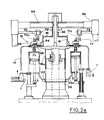
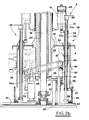
- - Figures 2a and 2b are cross sections along line II-II of Fig.1, showing the upper and lower sections of the aforesaid carousel, respectively;
- - Figure 3 is a plan view, with enlarged details, of the aforesaid grippers;
- - Figure 4 is a vertical, cross sectional view of one of the filling valves of the machine;
- - Figure 5 is a schematic plan view of the machine showing the different stages in the operation of the aforesaid filling valve;
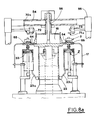
- - Figures 6a, 6b, 6c and 6d are partial cross sectional views of the machine during successive stages of operation;
- - Figure 7 is a cross section of the lower portion of the aforesaid carousel when the latter is set for filling bottles of the largest size.
- - Figures 8a and 8b are cross sections of the lower and upper portions of the aforesaid carousel, respectively, during cleaning of the aforesaid dispensing units.
- With reference to the drawings just listed, the machine for filling
bottles 1 with a liquid product has means 2 for feeding the said bottles to acarousel 3 which rotates about a vertical axis in the direction indicated by arrow A. - Feed means 2 consist of a
bottle 1 conveyingline 4 along which there is anauger 5 which rotates axially in such a manner as to space the conveyedbottles 1 apart. Auger 5 is designed to operate in conjunction with adistributor 6, shaped like a star, for example, which rotates in the direction of arrow B. - The bottles to be fed are held and guided by
recesses 6a indistributor 6 and byring guide 7 which partially surrounds the distributor itself. - Carousel 3 receives
bottles 1 fed bydistributor 6 one by one at the point where the equallyspaced grippers 8, mounted on the circumference of the carousel itself, are activated. Carousel 3 also mounts dispensing units, labelled 9 in the drawings, which fill the liquid product intobottles 1. - Downstream of
carousel 3 there is a full bottle outfeedsystem 10 consisting of aconveyor line 11 and anotherdistributor 12, shaped like a star, for example, which rotates in the direction of arrow C. - The outgoing bottles are received by
distributor 12 at the point where they are released bygrippers 8 and are held and guided byrecesses 12a in the distributor and by aring guide 13 which partially surrounds the distributor. - Dispensing units 9 consist of a plurality of cylinder and plunger assemblies mounted by
carousel 3 which lines them up withgrippers 8. Each of the said cylinder andplunger assemblies 14 is connected through avalve 15 to aliquid feed chamber 16 and to a fillingnozzle 17 alternately.Chamber 16 is mounted on aplatform 18 attached to the rotating part ofcarousel 3. -
Platform 18 is secured to the top of avertical shaft 19, rotated continuously by the drive motor of the machine through transmission means 20 located at the bottom of the said shaft where thelower face 21 of the carousel frame is situated. Shaft 19 is set inside atubular casing 22 which rotates with it. - At the top,
casing 22 is covered by acylindrical sleeve 18a formed underplatform 18. The base ofsleeve 18a is surrounded by atrap 23 which collects the washing liquid of cylinder andplunger assemblies 14 to which it is connected viatubes 23a. - Between
shaft 19 andcasing 22 and coaxial to them there is atubular element 24, with appropriate rotational means, about whichshaft 19 andcasing 22 rotate. The bottom end oftubular element 24 is attached to aplate 25 supported bycolumns 26 which pass throughplate 21 and are fixed toplate 27.Plate 21 is adjustably mounted for height in relation toplate 27 according to the size of the bottles to be filled. -
Grippers 8 and cylinder andplunger assemblies 14 are driven synchronously by drive means 28 which form a set of vertical columns arranged around the circumference ofcarousel 3. Each of the said drive means consists of afirst sleeve 29 the top of which mountscasing 30 ofgrippers 8 and which is axially crossed by astem 31. Thefirst sleeve 29 is in turn located inside asecond sleeve 32 at the top of which there is a crosswise fitting 32a attached to stem 33a ofplunger 33 of cylinder andplunger assembly 14. -
Second sleeve 32 is guided by abushing 34 mounted on the circumference of aplate 35 attached totubular casing 22. -
First sleeve 29, on the other hand, mounts on its bottom end aroller 36 which rotates about a radial axis in relation to the carousel, the said roller engaging acam 37 made on acylindrical wall 38 mounted onlower plate 21 and concentric with the axis of the carousel. - The bottom end of
stem 31 mounts alever 39 with aroller 40 that rotates about a vertical axis.Roller 40 engages aring cam 41 formed onlower plate 21, as shown in Fig.3. - As shown by enlarged details P and R in the said Fig. 3,
grippers 8 consist of a pair ofjaws casing 30 by means ofpins toothed gears Pin 42a has inserted in it afork 44 which engages apin 45 vertically attached to stem 31. The rotation ofstem 31 through a defined angle, by action ofcam 41, thus determines the rotation of the gear pair formed bytoothed gears jaws - The bottom end of the aforesaid
second sleeve 32 mounts aroller 46 which rotates diametrically in relation to the carousel.Roller 46 runs in agroove 47 defined by aring 48 aroundtubular casing 22. One side ofring 48 is hinged at the bottom to apivot 49 whose axis is horizontally tangent to a circle concentric with the axis of the carousel.Pivot 49 is mounted on asupport 50 fixed to a ring shaped disc supported horizontally by columns 52 standing onlower plate 21. On the side diametricallyopposite pivot 49,ring 48 is pivotally attached to stem 53a of anactuator 53. The said actuator is supported in vertical position bydisc 51. -
Chamber 16, concentric with the axis ofcarousel 3, is fed through atube 54 connected to a tank outside the machine. Tube 54 is located abovechamber 16, diametrically with respect tocarousel 3, and is supported by aframe 55 attached to the fixed structure ofcarousel 3. Tube 54 is connected to amouthpiece 56 leading out ofchamber 16 in accordance with the axis of rotation of the carousel. - As shown in detail in Fig.4,
valve 15 consists of alower casing 57 fixed tocarousel platform 18 and anupper casing 58 which rotates on apin 59 about the vertical axis ofvalve 15 itself and in relation tolower casing 57.Upper casing 58 has acap 60 held bypin 59 and pushed axially by aspring 61 which presses down oncasing 58. -
Lower casing 57 is crossed by a pair of parallel,vertical holes platform 18.Duct 64 leads out ofchamber 16, whilstduct 65 is connected to dispensingnozzle 17. -
Platform 18 is also crossed by avertical hole 66, whose bottom end is connected to cylinder andplunger assembly 14 and whose top end extends intolower casing 57 of the valve. The axes ofholes upper valve casing 58. - Upper, rotating
casing 58, on the other hand, is crossed by an approximatelysemicircular channel 67 in a horizontal plane. At each end and in the middle ofchannel 67 there are downward openingholes hole 66 toducts valve casing 58. -
Cap 60 of rotatingcasing 58 has on its top aneccentric pin 68 which rotates axially and held by a sprungbolt 69. -
Pin 68 is designed to intercept a pair ofcams carousel 3, the said cams being carried by fixedframe 55 of the carousel in diametrically opposite positions in relation to the axis of the carousel itself.Cams pin 68.Cams actuators positions cams - The method by which the bottles are filled will now be described starting from the moment when
grippers 8 and related cylinder andplunger assemblies 14, rotated bycarousel 3, move to the area where the aforesaid bottles, fed bydistributor 6, are picked up.Grippers 8 reach the said area with theirjaws bottle 1 to be filled. - The closing of
jaws cam 41, which at the said pickup area, causes stem 31 to rotate axially (refer to Fig. 3).Stem 31 is carried in direction A bycarousel 3, so thatroller 40 slides incam 41. The rotation ofstem 31 through a defined angle is transmitted to gear pair43a and 43b and hence tojaws - After being gripped by
jaws bottle 1 is lifted vertically, as shown by arrow D in Fig.6a, in such a way thatnozzle 17 of dispensing unit 9 is inserted into the mouth ofbottle 1. The raising of the bottle is achieved by the axial sliding of thefirst sleeve 29, attached to casing 30 ofgrippers 8. The said sliding motion is controlled bycam 37 in whichroller 36 carried bysleeve 29 slides. - During this stage,
channel 67 ofupper casing 58 ofvalve 15, is connected throughholes duct 64 and to hole 66 leading into cylinder andplunger assembly 14. The said cylinder andplunger assembly 14 is thus connected to feedchamber 16 and liquid is sucked into the cylinder whenplunger 33 is driven downwards in the direction of arrow E shown in Fig. 6a. - When
nozzle 17 has been inserted intobottle 1, cylinder andplunger assembly 14 is ready to discharge its fill of liquid. For this purpose,valve 15 switches the connection of cylinder andplunger assembly 14 fromliquid suction duct 64 toduct 65 which conveys the liquid tonozzle 17. To obtain this action,eccentric pin 68 of the valve is intercepted bycam 70, thus causingupper casing 58 of the valve to rotate in relation to lower, fixedcasing 57. In this way,channel 67 ofcasing 58 is connected throughholes duct 65, thus enabling the liquid to flow out through the nozzle. - The reciprocating motion of
plunger 33 of cylinder andplunger assembly 14 is achieved by the axial sliding ofsecond sleeve 32, attached to stem 33a of the plunger. This sliding motion is effected byroller 46, mounted bysleeve 32, which runs in the circumferential groove ofring 48. - The stroke of
plunger 33 may be adjusted by varying the angle ofring 48, usually set in an oblique plane in relation tocarousel 3. To adjust the stroke, the ring may be shifted usingactuator 53, to the side opposite itspivot 49, as shown schematically by dashedline 74 in Fig.2b. Adjusting the stroke of the plunger makes it possible to vary the amount of liquid to be filled into the bottles. - As it is being filled,
bottle 1 is gradually lowered, as shown by arrow G in Fig.6b, through the sliding offirst sleeve 29 controlled bycam 37. - When the bottle is full, the flow of liquid stops, whilst
bottle 1 continues moving down untilnozzle 17 is disengaged (refer to Fig. 6c). The flow of liquid is stopped bycam 71 which interceptseccentric pin 68, causingcasing 58 ofvalve 15 to rotate to the initial position, that is to say, withchannel 67 connected toduct 64 and cylinder andplunger assembly 14. At the same time, the next suction stage begins and liquid flows into cylinder and plunger assembly 14 (Fig. 6d). - The full bottle is transferred to
distributor 12 ofoutfeed system 10. To do this,cam 41causes jaws distributor 12 ofoutfeed system 10 can engage the bottle and move it away. Obviously, the work cycle described above is carried out by all the dispensing units mounted on the circumference ofcarousel 3. - The machine described thus makes it possible to synchronize the driving of cylinder and
plunger assembly 14, the opening and closing ofbottle grippers 8 and the vertical movement of the saidgrippers 8, in such a way as to work in conjunction withnozzle 17 of liquid dispensing units 9. - It should be stressed in particular that the above movements are obtained with a device that forms a sort of upright column arranged around
carousel 3. - The device therefore occupies very little space and allows easy access to the internal parts of the carousel.
- It should also be noted that the supply of liquid to dispensing units 9 is effected by a single valve for each dispensing
nozzle 17. The said valves are rotated bycarousel 3 and are fed by a chamber mounted on the same axis ascarousel 3 itself. The space occupied by the valves is thus very limited, making for a very practical set-up. - In addition, the machine may be adjusted in accordance with the size of the bottles to be filled, as shown in Fig. 7, which shows
carousel 3 set for filling bottles of the largest size. Such adjustment is effected by movingplate 21 upwards away fromplate 27 in such a manner as to also raise drive means 28, which are attached to plate 21, and thus vary the distance betweengrippers 8 and the feed level ofbottles 1, the said level being defined by rotary distributor 6 (position X in Figures 2b and 7). - Finally, Figures 8a and 8b show carousel when cylinder and
plunger assemblies 14 are being washed. To effect washing,ring 48 is moved to a horizontal position (position Y, Fig. 8b), by rotating it about itspivot 49 by means ofactuator 53. In this way,roller 46, which runs ingroove 47 ofring 48, is not moved in vertical direction and the reciprocating motion ofplunger 33 of cylinder andplunger assemblies 14 is stopped.Column 19 is lowered by means of elements 80 (Fig.8b).)n this way, plunger33 stops in the raised position Z (Fig. 8a) where the inside diameter of the cylindrical lining of cylinder andplunger assembly 14 is larger and does not form a hydraulic seal. At the same time,cams positions respective actuators valves 15.Valves 15 are stopped in the position wherechamber 16 is connected to cylinder andplunger assemblies 14. - Under these conditions, cylinder and
plunger assemblies 14 may be filled with an appropriate washing liquid . The washing liquid flows to the bottom of cylinder andplunger assemblies 14 and collects intrap 23.
Claims (12)
Applications Claiming Priority (2)
| Application Number | Priority Date | Filing Date | Title |
|---|---|---|---|
| IT00373390A IT1242877B (en) | 1990-11-14 | 1990-11-14 | METHOD AND MACHINE FOR FILLING CONTAINERS WITH LIQUID SUBSTANCES. |
| IT373390 | 1990-11-14 |
Publications (3)
| Publication Number | Publication Date |
|---|---|
| EP0486438A2 true EP0486438A2 (en) | 1992-05-20 |
| EP0486438A3 EP0486438A3 (en) | 1992-08-12 |
| EP0486438B1 EP0486438B1 (en) | 1995-05-10 |
Family
ID=11111575
Family Applications (1)
| Application Number | Title | Priority Date | Filing Date |
|---|---|---|---|
| EP91830490A Expired - Lifetime EP0486438B1 (en) | 1990-11-14 | 1991-11-12 | Method and machine for filling containers with liquid products |
Country Status (4)
| Country | Link |
|---|---|
| EP (1) | EP0486438B1 (en) |
| DE (1) | DE69109627T2 (en) |
| ES (1) | ES2071968T3 (en) |
| IT (1) | IT1242877B (en) |
Cited By (6)
| Publication number | Priority date | Publication date | Assignee | Title |
|---|---|---|---|---|
| WO2001085594A1 (en) * | 2000-05-05 | 2001-11-15 | I.M.A. Industria Macchine Automatiche S.P.A. | A machine for filling containers with a liquid substance |
| EP1647519A1 (en) * | 2004-10-14 | 2006-04-19 | MARCHESINI GROUP S.p.A. | Machine for filling containers with liquid products |
| FR2952036A1 (en) * | 2009-11-05 | 2011-05-06 | Lb Systems | Device for rotatably driving and guiding rotary valve of e.g. rotary agri-food dosing and filling machine, has Oldham coupling compensating radial and angular misalignments, where coupling is integrated to pulley that is rotated by belt |
| US20150183538A1 (en) * | 2013-12-30 | 2015-07-02 | Sidel S.P.A. Con Socio Unico | Unit for carrying out an operation on a container fillable with a pourable product |
| EP3421412A1 (en) * | 2017-06-30 | 2019-01-02 | Tetra Laval Holdings & Finance S.A. | Cam controlled system |
| CN116214119A (en) * | 2023-05-11 | 2023-06-06 | 汕头市铭信实业有限公司 | Adjustable press nozzle plug pipe assembling machine based on extrusion offset discharging and assembling method |
Families Citing this family (1)
| Publication number | Priority date | Publication date | Assignee | Title |
|---|---|---|---|---|
| CN108907712B (en) * | 2018-08-31 | 2023-07-25 | 济南大学 | Glass bottle production assembly equipment |
Citations (5)
| Publication number | Priority date | Publication date | Assignee | Title |
|---|---|---|---|---|
| US4108221A (en) * | 1976-08-06 | 1978-08-22 | Gerhart Engineering & Machine Co. | Container filling machine |
| FR2502606A1 (en) * | 1981-03-28 | 1982-10-01 | Seitz Werke Gmbh | CARROUSEL-TYPE FILLING MACHINE, EQUIPPED WITH ELEVATOR AND BOTTLE GRIPPING DEVICES |
| US4363649A (en) * | 1981-10-13 | 1982-12-14 | Toyo Garasu Kabushiki Kaisha | Apparatus for inspection of glass containers |
| EP0350974A2 (en) * | 1985-11-11 | 1990-01-17 | SIMONAZZI A. & L. S.p.A. | Continuous rotary bottle filler |
| DE3903768A1 (en) * | 1988-08-20 | 1990-03-01 | Seitz Enzinger Noll Masch | Method for filling containers, especially bottles, with a liquid material which is preferably under ambient pressure and a filling machine for implementing the method |
-
1990
- 1990-11-14 IT IT00373390A patent/IT1242877B/en active IP Right Grant
-
1991
- 1991-11-12 DE DE69109627T patent/DE69109627T2/en not_active Expired - Fee Related
- 1991-11-12 ES ES91830490T patent/ES2071968T3/en not_active Expired - Lifetime
- 1991-11-12 EP EP91830490A patent/EP0486438B1/en not_active Expired - Lifetime
Patent Citations (5)
| Publication number | Priority date | Publication date | Assignee | Title |
|---|---|---|---|---|
| US4108221A (en) * | 1976-08-06 | 1978-08-22 | Gerhart Engineering & Machine Co. | Container filling machine |
| FR2502606A1 (en) * | 1981-03-28 | 1982-10-01 | Seitz Werke Gmbh | CARROUSEL-TYPE FILLING MACHINE, EQUIPPED WITH ELEVATOR AND BOTTLE GRIPPING DEVICES |
| US4363649A (en) * | 1981-10-13 | 1982-12-14 | Toyo Garasu Kabushiki Kaisha | Apparatus for inspection of glass containers |
| EP0350974A2 (en) * | 1985-11-11 | 1990-01-17 | SIMONAZZI A. & L. S.p.A. | Continuous rotary bottle filler |
| DE3903768A1 (en) * | 1988-08-20 | 1990-03-01 | Seitz Enzinger Noll Masch | Method for filling containers, especially bottles, with a liquid material which is preferably under ambient pressure and a filling machine for implementing the method |
Cited By (9)
| Publication number | Priority date | Publication date | Assignee | Title |
|---|---|---|---|---|
| WO2001085594A1 (en) * | 2000-05-05 | 2001-11-15 | I.M.A. Industria Macchine Automatiche S.P.A. | A machine for filling containers with a liquid substance |
| US6701979B2 (en) | 2000-05-05 | 2004-03-09 | I.M.A. Industria Macchine Automatiche S.P.A. | Machine for filling containers with a liquid substance |
| EP1647519A1 (en) * | 2004-10-14 | 2006-04-19 | MARCHESINI GROUP S.p.A. | Machine for filling containers with liquid products |
| FR2952036A1 (en) * | 2009-11-05 | 2011-05-06 | Lb Systems | Device for rotatably driving and guiding rotary valve of e.g. rotary agri-food dosing and filling machine, has Oldham coupling compensating radial and angular misalignments, where coupling is integrated to pulley that is rotated by belt |
| US20150183538A1 (en) * | 2013-12-30 | 2015-07-02 | Sidel S.P.A. Con Socio Unico | Unit for carrying out an operation on a container fillable with a pourable product |
| US9914628B2 (en) * | 2013-12-30 | 2018-03-13 | Sidel S.P.A. Con Socio Unico | Unit for carrying out an operation on a container fillable with a pourable product |
| EP3421412A1 (en) * | 2017-06-30 | 2019-01-02 | Tetra Laval Holdings & Finance S.A. | Cam controlled system |
| WO2019002601A1 (en) * | 2017-06-30 | 2019-01-03 | Tetra Laval Holdings & Finance S.A. | Cam controlled system |
| CN116214119A (en) * | 2023-05-11 | 2023-06-06 | 汕头市铭信实业有限公司 | Adjustable press nozzle plug pipe assembling machine based on extrusion offset discharging and assembling method |
Also Published As
| Publication number | Publication date |
|---|---|
| IT1242877B (en) | 1994-05-18 |
| IT9003733A0 (en) | 1990-11-14 |
| IT9003733A1 (en) | 1992-05-14 |
| DE69109627T2 (en) | 1996-02-08 |
| EP0486438B1 (en) | 1995-05-10 |
| EP0486438A3 (en) | 1992-08-12 |
| DE69109627D1 (en) | 1995-06-14 |
| ES2071968T3 (en) | 1995-07-01 |
Similar Documents
| Publication | Publication Date | Title |
|---|---|---|
| EP0486439B1 (en) | Device for synchronously driving the dispensing and the container handling means in bottling machines | |
| US7114535B2 (en) | Circular motion filling machine and method | |
| CA1238614A (en) | Divergent conveyor type capsule separating filling and closing system | |
| US8333052B2 (en) | Machine for filling capsules with pharmaceutical products | |
| EP1251074A2 (en) | Device for gripping and handling bottles in a labelling machine and method of bottle filling/pressurising | |
| EP0486438B1 (en) | Method and machine for filling containers with liquid products | |
| US4168599A (en) | Packaging system | |
| GB898385A (en) | Improvements in or relating to apparatus for filling containers | |
| EP0486440B1 (en) | Device for dispensing liquid products to rotating elements, especially in bottling machines | |
| US4903740A (en) | Method and apparatus for minimizing foam in filling cartons | |
| US2749688A (en) | Automatic filling and sealing machine for ampuls or other small containers | |
| US2353519A (en) | Mechanism for charging containers | |
| JP3897394B2 (en) | Irregular container filling device | |
| US4712474A (en) | Automatic article handling and screen printing apparatus | |
| US8359815B2 (en) | Machine for filling capsules with pharmaceutical products | |
| US3032237A (en) | Cup dispenser | |
| EP0373396A1 (en) | Apparatus for filling containers | |
| EP0648676B1 (en) | Adjustable container return device for a variable stroke lifter system in a packaging apparatus | |
| JPH06144488A (en) | Device for cleaning rotary filling apparatus | |
| US4645060A (en) | Device for supplying tubes in a positive manner to the processing line of tube-filling machines, and particularly tube-filing and boxing machines | |
| US4862798A (en) | Cylindrical object screen printer with object centering means | |
| JP2011011048A (en) | Machine for filling capsule with pharmaceutical product | |
| JPS5940717B2 (en) | Gas filling capping device | |
| JPH06144490A (en) | Rotary filling apparatus | |
| RU2098346C1 (en) | Automatic packaging machine |
Legal Events
| Date | Code | Title | Description |
|---|---|---|---|
| PUAI | Public reference made under article 153(3) epc to a published international application that has entered the european phase |
Free format text: ORIGINAL CODE: 0009012 |
|
| AK | Designated contracting states |
Kind code of ref document: A2 Designated state(s): CH DE ES FR GB LI |
|
| PUAL | Search report despatched |
Free format text: ORIGINAL CODE: 0009013 |
|
| AK | Designated contracting states |
Kind code of ref document: A3 Designated state(s): CH DE ES FR GB LI |
|
| 17P | Request for examination filed |
Effective date: 19921030 |
|
| 17Q | First examination report despatched |
Effective date: 19930604 |
|
| GRAA | (expected) grant |
Free format text: ORIGINAL CODE: 0009210 |
|
| AK | Designated contracting states |
Kind code of ref document: B1 Designated state(s): CH DE ES FR GB LI |
|
| PG25 | Lapsed in a contracting state [announced via postgrant information from national office to epo] |
Ref country code: LI Effective date: 19950510 Ref country code: CH Effective date: 19950510 |
|
| REF | Corresponds to: |
Ref document number: 69109627 Country of ref document: DE Date of ref document: 19950614 |
|
| ET | Fr: translation filed | ||
| REG | Reference to a national code |
Ref country code: ES Ref legal event code: FG2A Ref document number: 2071968 Country of ref document: ES Kind code of ref document: T3 |
|
| REG | Reference to a national code |
Ref country code: CH Ref legal event code: PL |
|
| PLBE | No opposition filed within time limit |
Free format text: ORIGINAL CODE: 0009261 |
|
| STAA | Information on the status of an ep patent application or granted ep patent |
Free format text: STATUS: NO OPPOSITION FILED WITHIN TIME LIMIT |
|
| 26N | No opposition filed | ||
| REG | Reference to a national code |
Ref country code: GB Ref legal event code: IF02 |
|
| PGFP | Annual fee paid to national office [announced via postgrant information from national office to epo] |
Ref country code: DE Payment date: 20081128 Year of fee payment: 18 |
|
| PGFP | Annual fee paid to national office [announced via postgrant information from national office to epo] |
Ref country code: FR Payment date: 20081118 Year of fee payment: 18 Ref country code: ES Payment date: 20081127 Year of fee payment: 18 |
|
| PGFP | Annual fee paid to national office [announced via postgrant information from national office to epo] |
Ref country code: GB Payment date: 20081127 Year of fee payment: 18 |
|
| GBPC | Gb: european patent ceased through non-payment of renewal fee |
Effective date: 20091112 |
|
| REG | Reference to a national code |
Ref country code: FR Ref legal event code: ST Effective date: 20100730 |
|
| PG25 | Lapsed in a contracting state [announced via postgrant information from national office to epo] |
Ref country code: FR Free format text: LAPSE BECAUSE OF NON-PAYMENT OF DUE FEES Effective date: 20091130 |
|
| PG25 | Lapsed in a contracting state [announced via postgrant information from national office to epo] |
Ref country code: DE Free format text: LAPSE BECAUSE OF NON-PAYMENT OF DUE FEES Effective date: 20100601 |
|
| PG25 | Lapsed in a contracting state [announced via postgrant information from national office to epo] |
Ref country code: GB Free format text: LAPSE BECAUSE OF NON-PAYMENT OF DUE FEES Effective date: 20091112 |
|
| REG | Reference to a national code |
Ref country code: ES Ref legal event code: FD2A Effective date: 20110307 |
|
| PG25 | Lapsed in a contracting state [announced via postgrant information from national office to epo] |
Ref country code: ES Free format text: LAPSE BECAUSE OF NON-PAYMENT OF DUE FEES Effective date: 20110304 |
|
| PG25 | Lapsed in a contracting state [announced via postgrant information from national office to epo] |
Ref country code: ES Free format text: LAPSE BECAUSE OF NON-PAYMENT OF DUE FEES Effective date: 20091113 |