EP0486251B1 - Sheet handling apparatus - Google Patents
Sheet handling apparatus Download PDFInfo
- Publication number
- EP0486251B1 EP0486251B1 EP91310409A EP91310409A EP0486251B1 EP 0486251 B1 EP0486251 B1 EP 0486251B1 EP 91310409 A EP91310409 A EP 91310409A EP 91310409 A EP91310409 A EP 91310409A EP 0486251 B1 EP0486251 B1 EP 0486251B1
- Authority
- EP
- European Patent Office
- Prior art keywords
- pick
- pick mechanism
- notes
- drive
- note
- Prior art date
- Legal status (The legal status is an assumption and is not a legal conclusion. Google has not performed a legal analysis and makes no representation as to the accuracy of the status listed.)
- Expired - Lifetime
Links
Images

Classifications
-
- B—PERFORMING OPERATIONS; TRANSPORTING
- B65—CONVEYING; PACKING; STORING; HANDLING THIN OR FILAMENTARY MATERIAL
- B65H—HANDLING THIN OR FILAMENTARY MATERIAL, e.g. SHEETS, WEBS, CABLES
- B65H3/00—Separating articles from piles
- B65H3/44—Simultaneously, alternately, or selectively separating articles from two or more piles
-
- G—PHYSICS
- G07—CHECKING-DEVICES
- G07D—HANDLING OF COINS OR VALUABLE PAPERS, e.g. TESTING, SORTING BY DENOMINATIONS, COUNTING, DISPENSING, CHANGING OR DEPOSITING
- G07D11/00—Devices accepting coins; Devices accepting, dispensing, sorting or counting valuable papers
- G07D11/10—Mechanical details
- G07D11/16—Handling of valuable papers
-
- B—PERFORMING OPERATIONS; TRANSPORTING
- B65—CONVEYING; PACKING; STORING; HANDLING THIN OR FILAMENTARY MATERIAL
- B65H—HANDLING THIN OR FILAMENTARY MATERIAL, e.g. SHEETS, WEBS, CABLES
- B65H2301/00—Handling processes for sheets or webs
- B65H2301/30—Orientation, displacement, position of the handled material
- B65H2301/32—Orientation of handled material
- B65H2301/321—Standing on edge
-
- B—PERFORMING OPERATIONS; TRANSPORTING
- B65—CONVEYING; PACKING; STORING; HANDLING THIN OR FILAMENTARY MATERIAL
- B65H—HANDLING THIN OR FILAMENTARY MATERIAL, e.g. SHEETS, WEBS, CABLES
- B65H2403/00—Power transmission; Driving means
- B65H2403/20—Belt drives
- B65H2403/21—Timing belts
-
- B—PERFORMING OPERATIONS; TRANSPORTING
- B65—CONVEYING; PACKING; STORING; HANDLING THIN OR FILAMENTARY MATERIAL
- B65H—HANDLING THIN OR FILAMENTARY MATERIAL, e.g. SHEETS, WEBS, CABLES
- B65H2403/00—Power transmission; Driving means
- B65H2403/40—Toothed gearings
-
- B—PERFORMING OPERATIONS; TRANSPORTING
- B65—CONVEYING; PACKING; STORING; HANDLING THIN OR FILAMENTARY MATERIAL
- B65H—HANDLING THIN OR FILAMENTARY MATERIAL, e.g. SHEETS, WEBS, CABLES
- B65H2701/00—Handled material; Storage means
- B65H2701/10—Handled articles or webs
- B65H2701/19—Specific article or web
- B65H2701/1912—Banknotes, bills and cheques or the like
Definitions
- This invention relates to a sheet handling apparatus for removing sheets from stacks of sheets held in a plurality of containers and for feeding said sheets towards an output station.
- the invention has application, for example, to a cash dispenser unit of an automated teller machine (ATM) in which there is provided a currency note picking apparatus for extracting notes from a plurality of currency cassettes mounted in the cash dispenser unit.
- ATM automated teller machine
- a user inserts a customer identifying card into the machine and then enters certain data (such as codes, quantity of currency required or to be paid in, type of transaction, etc.) upon one or more keyboards associated with the machine.
- the machine will then process the transaction, update the user's account to reflect the current transaction, dispense cash, when requested, extracted from one or more of the currency cassettes, and return the card to the user as part of a routine operation.
- One known kind of cash dispenser unit of an ATM includes a plurality of currency note pick mechanisms each of which incorporates pivotably mounted pick arms disposed adjacent an associated currency cassette, the pick arms being arranged to draw part of an end note of a stack of notes in the cassette away from the remainder of the stack, by applying suction force to the end note, and to position said part for engagement by transport means arranged to remove the end note from the cassette.
- the transport means feed a plurality of notes one by one to note stacking means where the notes are stacked in a bundle, the bundle of notes then being fed to an output station, represented by a cash exit slot, for collection by a user of the ATM.
- a known cash dispenser unit has the disadvantage that, once a gulp feed has occurred, it is likely that a major gear change will be required before the pick mechanism can be used again with any confidence. Also, a known cash dispenser unit having a plurality of pick mechanisms has the further disadvantage that, once a gulp feed has occurred, the whole of the cash dispenser unit may be rendered non-operational until any note jam has been cleared and/or any necessary repairs have been carried out.
- a sheet handling apparatus for removing sheets one by one from a plurality of stacks of sheets respectively held in a plurality of containers and for feeding said sheets towards an output station
- said apparatus including sheet transport means, a plurality of pick mechanisms respectively associated with said containers, each pick mechanism being arranged to withdraw part of an end sheet of the stack held in the associated container away from the remainder of said stack to position said part for engagement by first and second roll means which are included in the pick mechanism and which are arranged to grip said end sheet therebetween for the purpose of removing said end sheet from the associated container, and a drive mechanism for said transport means and said plurality of pick mechanisms, said drive mechanism being driven in operation by an electric motor, characterized by a plurality of torque limiting devices included in said drive mechanism and respectively associated with said pick mechanisms, each torque limiting device including first and second rotatable members which rotate in the course of operation of the associated pick mechanism, said first member being arranged to apply a torque to said second member for the purpose of driving said first and second roll means of the associated pick mechanism, and
- the cash dispenser unit 10 shown therein includes two similar pick mechanisms 12 arranged one above the other and respectively associated with two currency cassettes 14 which are removably mounted in a supporting framework 16 of the dispenser 10.
- Each of the cassettes 14 is arranged to contain a stack of currency notes 18, corresponding long edges of which are supported on a horizontal support plate 20 mounted in the cassette 14.
- the two cassettes 14 respectively contain notes 18 of different denominations.
- the stack of notes 18 in each cassette 14 is urged by a spring loaded pusher member 22 (Fig. 1) towards a stop member 24 (Fig. 2) mounted at the front end (left hand end with reference to Figs. 1 and 2) of the cassette 14.
- An opening 26 (Fig. 2) is formed in the front end of each cassette 14, the opening 26 being normally closed by conventional shutter means (not shown) when the cassette 14 is not mounted in the dispenser unit 10.
- the relevant shutter means is automatically retracted away from its closed position so as to enable currency notes 18 to be extracted through the opening 26 by the associated pick mechanism 12.
- Brushes 28 are provided at the front end of the support plate 20 of each cassette 14 for a purpose which will be explained later.
- Each pick mechanism 12 includes a tubular member 30 which extends between, and is rotatably mounted with respect to, side walls 32 and 34 of the framework 16.
- Two conventional pick arms 36 each incorporating a rubber suction pad 38, are secured on each tubular member 30, each pick arm 36 communicating with the interior of the associated tubular member 30.
- Corresponding ends of the tubular members 30 project beyond the side wall 34, and are each connected by a respective swivel elbow connector 40 to a respective rubber tube 42 via which reduced pressure is applied in operation to the respective tubular member 30.
- a gear segment 44 is secured to that part of each tubular member 30 projecting beyond the side wall 34, the gear segment 44 being in cooperative engagement with a toothed end portion 46 of a first arm of a respective bell crank lever 48 which is pivotably mounted on a stud 50 secured to the outer surface of the wall 34.
- Each lever 48 is urged to rotate in a counterclockwise direction with reference to Fig. 2 by means of a spring 52 the ends of which are respectively attached to the side wall 34 and to the end of the second arm of the lever 48.
- a stud 54 is secured to one side of each lever 48, the stud 54 engaging in a cam track 56 formed in an associated cam member 58.
- Each cam member 58 is secured to a respective gear wheel 60 which is rotatably mounted on a respective shaft 62 projecting from the outer surface of the side wall 34.
- the gear wheels 60 are driven by gear wheels 64 forming part of a gear mechanism 65 (Fig. 4) operated by a main drive electric motor 66 (Figs. 4 and 9).
- a main drive electric motor 66 Figs. 4 and 9.
- the gear wheels 60 are rotated in a clockwise direction with reference to Fig. 2.
- This rotation of the gear wheels 60 brings about an oscillatory pivotal movement of the levers 48 by virtue of the engagement of the studs 54 in the cam tracks 56, the springs 52 holding the studs 54 in engagement with the inner edges of the cam tracks 56.
- the oscillatory movement of the levers 48 brings about an oscillatory pivotal movement of the assemblies of the tubular members 30 and the associated pick arms 36.
- the oscillatory movement of either of the assemblies of the tubular members 30 and associated pick arms 36 is effective to cause currency notes to be picked one by one from the stack of currency notes 18 held in the associated currency cassette 14.
- a timing disc 68 is secured to that face of each gear wheel 60 remote from the associated cam member 58.
- Each timing disc 68 is for the most part transparent but incorporates an arcuate opaque strip 70 extending around just over half the periphery of the disc 68.
- Each timing disc 68 is associated with optical sensing means, comprising an LED (not shown) and a cooperating phototransistor sensor 73, which is arranged to sense the opaque strip 70.
- optical sensing means comprising an LED (not shown) and a cooperating phototransistor sensor 73, which is arranged to sense the opaque strip 70.
- the associated sensor 73 In operation, as each assembly of a gear wheel 60 and the associated cam member 58 and timing disc 68 rotates in response to energization of the motor 66, the associated sensor 73 generates output signals in response to the sensing of the leading and trailing edges of the associated opaque strip 70. It should be understood that the signals generated by each of the sensors 73 provide indications as to the precise positions of the associated pick arms 36
- each pick mechanism 12 also includes a first pair of rolls 74 secured on a drive shaft 76, and a second pair of rolls 78 (hereinafter referred to as cam rolls) which are secured on a drive shaft 80 in cooperative relationship with respect to the rolls 74, and whose peripheries comprise low portions 82 and high portions 83.
- the drive shafts 76 and 80 extend between, and are rotatably mounted with respect to, the side walls 32 and 34, and are respectively driven by two gear wheels 84 and 85 forming part of the gear mechanism 65 so that in operation the rolls 74 and the cam rolls 78 respectively rotate in clockwise and counterclockwise directions with reference to Fig.
- the rolls 74 and the cam rolls 78 making two revolutions for each revolution of the timing discs 68.
- the lower long edge of the first currency note 18′ of the stack of notes 18 in the relevant cassette 14 is pulled partly out of the cassette 14, under the action of suction force applied by the respective pick arms 36, and is fed between the low portions 82 of the respective cam rolls 78 and the associated rolls 74 as the arms 36 are pivoted in a clockwise direction from the position 36′ shown in chain outline in Fig. 2 to the position shown in solid outline.
- the note 18′ is thereafter pulled completely out of the cassette 14 by virtue of being gripped between the rolls 74 and the high portions 83 of the cam rolls 78.
- the cash dispenser unit 10 includes two note transport mechanisms 86 respectively associated with the two pick mechanisms 12, the transport mechanisms 86 being driven by the gear mechanism 65 previously referred to.
- Each transport mechanism 86 includes guide means 87 (Fig. 2) and sets of feed rolls 88, 90, 92, 94, and 96 for feeding a currency note picked by the associated pick mechanism 12 along a respective feed path 98 towards a further transport mechanism 100 which is positioned above the mechanisms 86 and which is also driven by the motor 66 via transmission means (not shown).
- the transport mechanism 100 serves to feed currency notes one by one to a conventional stacking wheel 102.
- the sets of cam rolls 78 and cooperating rolls 74 of each pick mechanism 12 feed a picked currency note to cooperating sets of rolls 88 and 90, from where the note is fed by cooperating sets of rolls 90 and 92 and cooperating sets of rolls 94 and 96 upwardly out of the respective transport mechanism 86.
- the upper one of the transport mechanisms 86 additionally includes two further sets of cooperating rolls 104 for accepting a currency note fed upwardly out of the lower transport mechanism 86 and for feeding this note to the cooperating rolls 90 and 92 of the upper mechanism 86, from where the note is fed to the transport mechanism 100.
- the stacking wheel 102 is driven by the motor 66 and is arranged to rotate continuously in operation in a counterclockwise direction. Means (not shown) are provided between the upper transport mechanism 86 and the stacking wheel 102 for detecting any multiple feeding of notes and for detecting any invalid or torn note.
- the stacking wheel 102 comprises a plurality of stacking plates 110 spaced apart in parallel relationship along the stacker wheel shaft 112, each stacking plate 110 incorporating a series of curved tines 114.
- the tines 114 of the stacking plates 110 pass between portions 116 of a rockably mounted stripper plate assembly 118.
- each note fed by the transport mechanism 100 to the stacking wheel 102 enters between adjacent tines 114 and is carried partly around the axis of the stacking wheel 102, the note being stripped from the wheel 102 by the portions 116 and being stacked against belt means 120 with a long edge of the note resting on the stripper plate assembly 118.
- the belt means 120 cooperates with belt means 122 normally held in the position shown in Fig. 1.
- the belt means 122 When a bundle of notes 18 ⁇ (or possibly a single note only) to be dispensed to a user in response to a cash withdrawal request has been stacked against the belt means 120, the belt means 122 is rocked in a clockwise direction about a shaft 124 so as to trap the bundle of notes 18 ⁇ between the belt means 120 and the belt means 122. It should be understood that in the course of this rocking movement separate belts making up the belt means 122 pass between adjacent pairs of the stacking plates 110.
- the belt means 120 and 122 are operated so as to drive the bundle 18 ⁇ to a pair of drive belt means 126 and 128.
- the belt means 126 and 128 serve to drive the bundle 18 ⁇ through a note exit slot 130 in a housing 132 of the ATM to a position where the bundle 18 ⁇ can be collected by the user of the ATM, a shutter 134, which serves to close the slot 130 when the ATM is not in operation, having previously been retracted to an open position.
- the belt means 120 and 122 are mounted in resilient relationship relative to each other, and the belt means 126 and 128 are also mounted in resilient relationship relative to each other, so that bundles of notes of varying thickness can be held between, and fed by, the belt means 120 and 122 and the belt means 126 and 128. If a multiple feeding has been detected in the course of stacking the bundle of notes 18 ⁇ against the belt means 120, or if one or more of the notes in the bundle 18 ⁇ have been rejected for any other reason, then the stripper plate assembly 118 is rocked into the position shown in chain outline in Fig. 1, and the belt means 120 and 122 are operated to feed the bundle 18 ⁇ in a direction opposite to the normal feed direction, the bundle 18 ⁇ being deposited in a reject note container 136 via an opening in the top thereof.
- the gear mechanism 65 which is driven by the electric motor 66 via belts 138 and pulleys 140 (Fig. 4), includes two torque limiting mechanisms 142 respectively associated with the two pick mechanisms 12.
- Each torque limiting mechanism 142 comprises a drive member 144 (best shown in Figs. 5A and 5B), and a driven member 146 (best shown in Figs. 6A and 6B), each of the members 144 and 146 being of unitary construction and being formed of moulded plastic such as an acetal resin.
- the drive member 144 includes a hollow cylindrical hub portion 148 formed integral at one end with a gear wheel portion 150.
- a resilient tripping finger 152 projects from the outer surface of the hub member 148, the free end portion 154 of the tripping finger 152 having a rounded extremity 156 facing away from the hub portion 148.
- the end portion 154 is offset in a counterclockwise direction (with reference to Fig. 5B) from the portion 158 of the tripping finger 152 which adjoins the hub portion 148.
- the portions 154 and 158 of the tripping finger 152 are connected together by an integral central portion 160 which extends around approximately one eighth of the circumference of the hub portion 148. As seen in Fig.
- the tripping finger 152 extends over the major part of the length of the hub portion 148, with the end portion 154 extending parallel to the axis of the drive member 144.
- the tripping finger 152 is so constructed that the end portion 154 can be moved inwardly towards the hub portion 148 against the spring action of the finger 152, this spring action tending to restore the finger 152 to its original position.
- the driven member 146 comprises a hollow cylindrical portion 162 and a gear wheel portion 164, the cylindrical portion 162 being integral at one end with the gear wheel portion 164.
- a recess 166 which has a rounded configuration and which extends along the whole length of the cylindrical portion 162 is formed in the inner surface of the portion 162.
- the length of the cylindrical portion 162 is slightly greater than the dimension of the tripping finger 152 parallel to the axis of the drive member 144.
- each torque limiting mechanism 142 is rotatably mounted on a respective shaft 168 (Figs. 3, 4 and 7) which extends between the side walls 32 and 34. As shown in Figs. 3 and 4, the gear wheel portion 150 of the drive member 144 engages with a respective gear wheel 170 of the gear mechanism 65.
- the driven member 146 of each torque limiting mechanism 142 is rotatably mounted on the respective shaft 168 with the tripping finger 152 of the drive member 144 disposed inside the cylindrical portion 162 of the driven member 146, the extremity 156 of the end portion 154 nesting in the recess 166 as shown in Fig. 7.
- the resilient nature of the tripping finger 152 holds the extremity 156 of the end portion 154 resiliently in position in the recess 166.
- the gear wheel portion 164 of the driven member 146 engages with the respective gear wheel 84.
- the drive member 144 of each torque limiting mechanism 142 is driven by the respective gear wheel 170 in a counterclockwise direction with reference to Figs. 4 and 7.
- this drive is transmitted via the relevant tripping finger 152 to the respective driven member 146 which in turn drives the gear wheels 84, 85, 64 and 60 of the respective pick mechanism 12, thereby rendering this pick mechanism 12 operational.
- the end portion 154 of the tripping finger 152 is offset from the portion 158 in a direction opposite to the direction of rotation of the drive member 144. As will be explained in more detail later, if due to a malfunction in the pick mechanism 12 the torque applied by the drive member 144 to the driven member 146 exceeds a certain limit, then the end portion 154 of the tripping finger 152 is displaced towards the relevant hub portion 148 out of engagement with the recess 166, against the spring action of the tripping finger 152, thereby allowing the drive member 144 to rotate relative to the driven member 146 with the driven member 146 and the associated rolls 74 and 78 being stationary.
- the drive member 144 can continue to rotate relative to the driven member 146 with no drive being transmitted to the relevant pick mechanism 12. It should be understood that although the drive to the pick mechanism 12 in which the malfunction occurred is disconnected, drive continues to be applied in normal manner to the other pick mechanism 12 via the respective torque limiting mechanism 142.
- the operation of the cash dispenser unit 10 will now be described with additional reference to Figs. 8A and 8B and Fig. 9. This operation is controlled by electronic control means 172 (Fig. 9) of the cash dispenser unit 10.
- the electronic control means 172 is connected to the motor 66, to each phototransistor sensor 73, and to a suction control means 174 of each pick mechanism 12.
- the control means 172 sends a signal to the motor 66 so as to switch on the motor 66 and cause the assemblies of the gear wheels 60, cams 58 and timing discs 68 to commence to rotate.
- the electronic control means 172 initiates the sending of signals to the suction control means 174 of a selected one of the pick mechanisms 12 so as to connect the tubular member 30 of the selected pick mechanism 12 in controlled manner to a source (not shown) of the reduced pressure, thereby initiating the picking of notes from the associated cassette 14.
- the timing of the application of reduced pressure to the tubular member 30, and hence to the associated suction pads 38, is under the control of signals generated by the phototransistor sensor 73 of the selected pick mechanism 12.
- the pick arms 36 of this pick mechanism 12 will undergo an oscillatory movement.
- the pick arms 36 apply a suction force to the first note 18′ of the stack of notes 18 held in the cassette 14 so as to pull the lower part of the note 18′ out of the cassette 14 until the lower end of the note 18′ comes into contact with the set of rolls 74.
- the rolls 74 and 78 pull the note 18′ away from the cassette 14 until the leading edge of the note 18′ enters the nip of the rolls 88 and 90 of the associated transport mechanism 86, after which the note 18′ is pulled completely out of the cassette 14 and fed to the stacking wheel 102 in the manner previously described.
- the electronic control means 172 may cause a series of further pick operations to be carried out in each of which a currency note is picked from one or other of the cassettes 14.
- the control means 172 Upon the control means 172 ascertaining that the correct number and denomination of currency notes have been picked from the cassettes 14, the control means 172 returns the cash dispenser unit 10 to its quiescent condition by de-energizing the motor 66.
- the brushes 28 will normally prevent the second note from being drawn out of the cassette 14 together with the first note 18′, since, in the event of the first and second notes commencing to be drawn out of the cassette 14, the brushes 28 flex the lower ends of these notes, thereby interrupting the application of suction force to the second note and so permitting the second note to fall back into its correct position in the cassette 14.
- a bunch of notes 18′′′ may be drawn out of the cassette 14 and become gripped between the rolls 74 and the leading edges of the high portions 83 of the cam rolls 78 as shown in Fig. 8B.
- an immediate increase occurs in the torque applied by the drive member 144 of the relevant torque limiting mechanism 142 to the associated driven member 146.
- this torque will be greater than the limit previously referred to, thereby causing the end portion 154 of the tripping finger 152 of the drive member 144 to become disengaged from the associated recess 166 so as to disconnect the drive to the relevant pick mechanism 12.
- the electronic control means 172 In response to the sensor 73 of the relevant pick mechanism 12 ceasing to apply timing pulses to the electronic control means 172 (which pulses are generated in synchronism with the rotation of the relevant rolls 74 and 78), the electronic control means 172 sends a signal over an output line 176 to the main ATM processor (not shown), this signal indicating that a gulp feed has occurred in the cash dispenser unit 10, and identifying the pick mechanism 12 in which the gulp feed occurred.
- each torque limiting device 142 is such that, when the relevant pick mechanism 12 recommences operation, the drive member 144 re-engages with the associated driven member 146 in exactly the same rotational position relative to the other parts of the pick mechanism 12 as it was in when disengagement occurred.
- torque limiting devices 142 provide a simple, cheap and effective means of protecting the cash dispenser unit 10 from damage in the event of a gulp feed occurring.
- the present invention reduces the time that the cash dispenser unit is out of operation as a result of a malfunction occurring in one or another of the pick mechanisms 12.
- picking of multiple notes having an overall thickness of not more than 2 millimetres by one of the pick mechanisms 12 will not cause a jam or any damage to the gear mechanism 65, such multiple notes being detected by the multiple note detect means previously referred to and being diverted to the reject note container 136.
- a cash dispenser unit in accordance with the invention could incorporate more than two pick mechanisms each associated with a respective currency cassette and with a respective torque limiting mechanism. Again, in the case of this alternative arrangement, the cash dispenser unit would remain operational even though drive to one of the pick mechanism may have been disconnected as a result of a gulp feed occurring in that mechanism, each of the other pick mechanisms remaining fully operational.
Landscapes
- Engineering & Computer Science (AREA)
- Mechanical Engineering (AREA)
- Physics & Mathematics (AREA)
- General Physics & Mathematics (AREA)
- Sheets, Magazines, And Separation Thereof (AREA)
Description
- This invention relates to a sheet handling apparatus for removing sheets from stacks of sheets held in a plurality of containers and for feeding said sheets towards an output station.
- The invention has application, for example, to a cash dispenser unit of an automated teller machine (ATM) in which there is provided a currency note picking apparatus for extracting notes from a plurality of currency cassettes mounted in the cash dispenser unit. As is well known, in operation of an ATM a user inserts a customer identifying card into the machine and then enters certain data (such as codes, quantity of currency required or to be paid in, type of transaction, etc.) upon one or more keyboards associated with the machine. The machine will then process the transaction, update the user's account to reflect the current transaction, dispense cash, when requested, extracted from one or more of the currency cassettes, and return the card to the user as part of a routine operation.
- One known kind of cash dispenser unit of an ATM (see GB-A-2 182 716) includes a plurality of currency note pick mechanisms each of which incorporates pivotably mounted pick arms disposed adjacent an associated currency cassette, the pick arms being arranged to draw part of an end note of a stack of notes in the cassette away from the remainder of the stack, by applying suction force to the end note, and to position said part for engagement by transport means arranged to remove the end note from the cassette. In a typical cash dispensing operation, the transport means feed a plurality of notes one by one to note stacking means where the notes are stacked in a bundle, the bundle of notes then being fed to an output station, represented by a cash exit slot, for collection by a user of the ATM.
- It can sometimes happen that, in operation of a currency note pick mechanism of a cash dispenser unit, due to a malfunction of the mechanism a so-called gulp feed occurs in which a plurality of currency notes, instead of a single note, are erroneously picked from the cassette in one cycle of operation of the pick mechanism. Such a malfunction may occur, for example, if the cassette has been loaded incorrectly, or if a note pusher mechanism in the cassette has become jammed. When a gulp feed occurs, the gear wheels driving the note transport means may be highly stressed and one or more gear wheels may fail. Even though only one gear wheel may fail as a result of a gulp feed, all other gears in the driving system will have been so highly stressed that it is likely that further use will soon result in more failures. Thus, a known cash dispenser unit has the disadvantage that, once a gulp feed has occurred, it is likely that a major gear change will be required before the pick mechanism can be used again with any confidence. Also, a known cash dispenser unit having a plurality of pick mechanisms has the further disadvantage that, once a gulp feed has occurred, the whole of the cash dispenser unit may be rendered non-operational until any note jam has been cleared and/or any necessary repairs have been carried out.
- It is an object of the present invention to provide a sheet handling apparatus of the kind including a plurality of pick mechanisms for removing sheets from a plurality of containers, in which the above mentioned disadvantages are substantially overcome.
- According to the invention there is provided a sheet handling apparatus for removing sheets one by one from a plurality of stacks of sheets respectively held in a plurality of containers and for feeding said sheets towards an output station, said apparatus including sheet transport means, a plurality of pick mechanisms respectively associated with said containers, each pick mechanism being arranged to withdraw part of an end sheet of the stack held in the associated container away from the remainder of said stack to position said part for engagement by first and second roll means which are included in the pick mechanism and which are arranged to grip said end sheet therebetween for the purpose of removing said end sheet from the associated container, and a drive mechanism for said transport means and said plurality of pick mechanisms, said drive mechanism being driven in operation by an electric motor, characterized by a plurality of torque limiting devices included in said drive mechanism and respectively associated with said pick mechanisms, each torque limiting device including first and second rotatable members which rotate in the course of operation of the associated pick mechanism, said first member being arranged to apply a torque to said second member for the purpose of driving said first and second roll means of the associated pick mechanism, and each torque limiting device being arranged to disconnect drive to said first and second roll means of the associated pick mechanism in the event of the torque applied by said first member of the device to said second member exceeding a predetermined limit, while permitting drive to continue to be applied to the or each other pick mechanism.
- One embodiment of the invention will now be described by way of example with reference to the accompanying drawings, in which:-
- Fig. 1 is a schematic side elevational view of a cash dispenser unit of an ATM having two pick mechanisms, with parts of said unit being omitted;
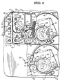
- Fig. 2 is an enlarged part sectional side elevational view of part of the cash dispenser unit of Fig. 1, shown partly broken away;
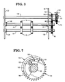
- Fig. 3 is a elevational view of part of one of the pick mechanisms, the view being taken in the direction of the arrow A in Fig. 2;
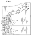
- Fig. 4 is a side elevational view showing the drive mechanism for the pick mechanisms and associated transport mechanisms;
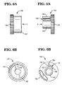
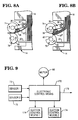
- Figs. 5A and 5B are respectively enlarged side and end views of a drive member of a torque limiting mechanism included in the drive mechanism of Fig. 4, the view shown in Fig. 5B being taken in the direction of the arrow B in Fig. 5A;
- Figs. 6A and 6B are respectively enlarged side and end views of a driven member of the torque limiting mechanism, the view shown in Fig. 6B being taken in the direction of the arrow C in Fig. 6A;
- Fig. 7, on the sheet with Fig. 3, is a side view of the torque limiting mechanism of Figs. 5 and 6 shown mounted on a respective shaft, with part of the drive member being broken away;
- Figs. 8A and 8B are schematic views respectively illustrating a normal pick operation and a pick operation involving a gulp feed; and
- Fig. 9 is a schematic block diagram illustrating electrical interconnections between parts of the cash dispenser unit.
- Referring to Fig. 1, the
cash dispenser unit 10 shown therein includes twosimilar pick mechanisms 12 arranged one above the other and respectively associated with twocurrency cassettes 14 which are removably mounted in a supportingframework 16 of thedispenser 10. Each of thecassettes 14 is arranged to contain a stack ofcurrency notes 18, corresponding long edges of which are supported on ahorizontal support plate 20 mounted in thecassette 14. The twocassettes 14 respectively containnotes 18 of different denominations. - Referring now additionally to Fig. 2, the stack of
notes 18 in eachcassette 14 is urged by a spring loaded pusher member 22 (Fig. 1) towards a stop member 24 (Fig. 2) mounted at the front end (left hand end with reference to Figs. 1 and 2) of thecassette 14. An opening 26 (Fig. 2) is formed in the front end of eachcassette 14, the opening 26 being normally closed by conventional shutter means (not shown) when thecassette 14 is not mounted in thedispenser unit 10. When acassette 14 is mounted in its correct operational position in thedispenser unit 10, the relevant shutter means is automatically retracted away from its closed position so as to enablecurrency notes 18 to be extracted through theopening 26 by theassociated pick mechanism 12. Brushes 28 are provided at the front end of thesupport plate 20 of eachcassette 14 for a purpose which will be explained later. - Each
pick mechanism 12 includes atubular member 30 which extends between, and is rotatably mounted with respect to,side walls framework 16. Twoconventional pick arms 36, each incorporating arubber suction pad 38, are secured on eachtubular member 30, eachpick arm 36 communicating with the interior of the associatedtubular member 30. Corresponding ends of thetubular members 30 project beyond theside wall 34, and are each connected by a respectiveswivel elbow connector 40 to arespective rubber tube 42 via which reduced pressure is applied in operation to the respectivetubular member 30. - A
gear segment 44 is secured to that part of eachtubular member 30 projecting beyond theside wall 34, thegear segment 44 being in cooperative engagement with atoothed end portion 46 of a first arm of a respectivebell crank lever 48 which is pivotably mounted on astud 50 secured to the outer surface of thewall 34. Eachlever 48 is urged to rotate in a counterclockwise direction with reference to Fig. 2 by means of aspring 52 the ends of which are respectively attached to theside wall 34 and to the end of the second arm of thelever 48. Astud 54 is secured to one side of eachlever 48, thestud 54 engaging in acam track 56 formed in an associatedcam member 58. Eachcam member 58 is secured to arespective gear wheel 60 which is rotatably mounted on arespective shaft 62 projecting from the outer surface of theside wall 34. Thegear wheels 60 are driven bygear wheels 64 forming part of a gear mechanism 65 (Fig. 4) operated by a main drive electric motor 66 (Figs. 4 and 9). In operation, with themotor 66 energized, thegear wheels 60 are rotated in a clockwise direction with reference to Fig. 2. This rotation of thegear wheels 60 brings about an oscillatory pivotal movement of thelevers 48 by virtue of the engagement of thestuds 54 in thecam tracks 56, thesprings 52 holding thestuds 54 in engagement with the inner edges of thecam tracks 56. By virtue of the engagement of thegear segments 44 with thetoothed portions 46 of thelevers 48, the oscillatory movement of thelevers 48 brings about an oscillatory pivotal movement of the assemblies of thetubular members 30 and the associatedpick arms 36. As will be explained in more detail later, the oscillatory movement of either of the assemblies of thetubular members 30 and associatedpick arms 36 is effective to cause currency notes to be picked one by one from the stack ofcurrency notes 18 held in the associatedcurrency cassette 14. - A
timing disc 68 is secured to that face of eachgear wheel 60 remote from the associatedcam member 58. Eachtiming disc 68 is for the most part transparent but incorporates an arcuateopaque strip 70 extending around just over half the periphery of thedisc 68. Eachtiming disc 68 is associated with optical sensing means, comprising an LED (not shown) and a cooperatingphototransistor sensor 73, which is arranged to sense theopaque strip 70. In operation, as each assembly of agear wheel 60 and the associatedcam member 58 andtiming disc 68 rotates in response to energization of themotor 66, theassociated sensor 73 generates output signals in response to the sensing of the leading and trailing edges of the associatedopaque strip 70. It should be understood that the signals generated by each of thesensors 73 provide indications as to the precise positions of the associatedpick arms 36 at the times when these signals are generated. - Referring now also to Fig. 3, each
pick mechanism 12 also includes a first pair ofrolls 74 secured on adrive shaft 76, and a second pair of rolls 78 (hereinafter referred to as cam rolls) which are secured on adrive shaft 80 in cooperative relationship with respect to therolls 74, and whose peripheries compriselow portions 82 andhigh portions 83. Thedrive shafts side walls gear wheels gear mechanism 65 so that in operation therolls 74 and thecam rolls 78 respectively rotate in clockwise and counterclockwise directions with reference to Fig. 2, therolls 74 and thecam rolls 78 making two revolutions for each revolution of thetiming discs 68. In the course of a normal pick operation, the lower long edge of thefirst currency note 18′ of the stack ofnotes 18 in therelevant cassette 14 is pulled partly out of thecassette 14, under the action of suction force applied by therespective pick arms 36, and is fed between thelow portions 82 of therespective cam rolls 78 and the associatedrolls 74 as thearms 36 are pivoted in a clockwise direction from theposition 36′ shown in chain outline in Fig. 2 to the position shown in solid outline. Thenote 18′ is thereafter pulled completely out of thecassette 14 by virtue of being gripped between therolls 74 and thehigh portions 83 of thecam rolls 78. - The
cash dispenser unit 10 includes twonote transport mechanisms 86 respectively associated with the twopick mechanisms 12, thetransport mechanisms 86 being driven by thegear mechanism 65 previously referred to. Eachtransport mechanism 86 includes guide means 87 (Fig. 2) and sets offeed rolls associated pick mechanism 12 along arespective feed path 98 towards afurther transport mechanism 100 which is positioned above themechanisms 86 and which is also driven by themotor 66 via transmission means (not shown). Thetransport mechanism 100 serves to feed currency notes one by one to aconventional stacking wheel 102. The sets ofcam rolls 78 and cooperatingrolls 74 of eachpick mechanism 12 feed a picked currency note to cooperating sets ofrolls rolls rolls respective transport mechanism 86. The upper one of thetransport mechanisms 86 additionally includes two further sets of cooperatingrolls 104 for accepting a currency note fed upwardly out of thelower transport mechanism 86 and for feeding this note to the cooperatingrolls upper mechanism 86, from where the note is fed to thetransport mechanism 100. - Referring now particularly to Fig. 1, the
stacking wheel 102 is driven by themotor 66 and is arranged to rotate continuously in operation in a counterclockwise direction. Means (not shown) are provided between theupper transport mechanism 86 and the stackingwheel 102 for detecting any multiple feeding of notes and for detecting any invalid or torn note. The stackingwheel 102 comprises a plurality of stackingplates 110 spaced apart in parallel relationship along thestacker wheel shaft 112, each stackingplate 110 incorporating a series ofcurved tines 114. Thetines 114 of the stackingplates 110 pass betweenportions 116 of a rockably mountedstripper plate assembly 118. In operation, each note fed by thetransport mechanism 100 to the stackingwheel 102 enters betweenadjacent tines 114 and is carried partly around the axis of the stackingwheel 102, the note being stripped from thewheel 102 by theportions 116 and being stacked against belt means 120 with a long edge of the note resting on thestripper plate assembly 118. The belt means 120 cooperates with belt means 122 normally held in the position shown in Fig. 1. When a bundle ofnotes 18˝ (or possibly a single note only) to be dispensed to a user in response to a cash withdrawal request has been stacked against the belt means 120, the belt means 122 is rocked in a clockwise direction about ashaft 124 so as to trap the bundle ofnotes 18˝ between the belt means 120 and the belt means 122. It should be understood that in the course of this rocking movement separate belts making up the belt means 122 pass between adjacent pairs of the stackingplates 110. - Assuming that none of the notes in the
bundle 18˝ have been rejected for any reason, the belt means 120 and 122 are operated so as to drive thebundle 18˝ to a pair of drive belt means 126 and 128. The belt means 126 and 128 serve to drive thebundle 18˝ through anote exit slot 130 in ahousing 132 of the ATM to a position where thebundle 18˝ can be collected by the user of the ATM, ashutter 134, which serves to close theslot 130 when the ATM is not in operation, having previously been retracted to an open position. It should be understood that the belt means 120 and 122 are mounted in resilient relationship relative to each other, and the belt means 126 and 128 are also mounted in resilient relationship relative to each other, so that bundles of notes of varying thickness can be held between, and fed by, the belt means 120 and 122 and the belt means 126 and 128. If a multiple feeding has been detected in the course of stacking the bundle ofnotes 18˝ against the belt means 120, or if one or more of the notes in thebundle 18˝ have been rejected for any other reason, then thestripper plate assembly 118 is rocked into the position shown in chain outline in Fig. 1, and the belt means 120 and 122 are operated to feed thebundle 18˝ in a direction opposite to the normal feed direction, thebundle 18˝ being deposited in areject note container 136 via an opening in the top thereof. - Referring now again to Fig. 3, together with Figs. 4, 5A and 5B, 6A and 6B and Fig. 7, the
gear mechanism 65, which is driven by theelectric motor 66 viabelts 138 and pulleys 140 (Fig. 4), includes twotorque limiting mechanisms 142 respectively associated with the twopick mechanisms 12. Eachtorque limiting mechanism 142 comprises a drive member 144 (best shown in Figs. 5A and 5B), and a driven member 146 (best shown in Figs. 6A and 6B), each of themembers - Referring particularly to Figs. 5A and 5B, the
drive member 144 includes a hollowcylindrical hub portion 148 formed integral at one end with agear wheel portion 150. A resilient trippingfinger 152 projects from the outer surface of thehub member 148, thefree end portion 154 of the trippingfinger 152 having arounded extremity 156 facing away from thehub portion 148. Theend portion 154 is offset in a counterclockwise direction (with reference to Fig. 5B) from theportion 158 of the trippingfinger 152 which adjoins thehub portion 148. Theportions finger 152 are connected together by an integralcentral portion 160 which extends around approximately one eighth of the circumference of thehub portion 148. As seen in Fig. 5A, the trippingfinger 152 extends over the major part of the length of thehub portion 148, with theend portion 154 extending parallel to the axis of thedrive member 144. The trippingfinger 152 is so constructed that theend portion 154 can be moved inwardly towards thehub portion 148 against the spring action of thefinger 152, this spring action tending to restore thefinger 152 to its original position. - Referring particularly to Figs. 6A and 6B, the driven
member 146 comprises a hollowcylindrical portion 162 and agear wheel portion 164, thecylindrical portion 162 being integral at one end with thegear wheel portion 164. Arecess 166 which has a rounded configuration and which extends along the whole length of thecylindrical portion 162 is formed in the inner surface of theportion 162. The length of thecylindrical portion 162 is slightly greater than the dimension of the trippingfinger 152 parallel to the axis of thedrive member 144. - The
drive member 144 of eachtorque limiting mechanism 142 is rotatably mounted on a respective shaft 168 (Figs. 3, 4 and 7) which extends between theside walls gear wheel portion 150 of thedrive member 144 engages with arespective gear wheel 170 of thegear mechanism 65. The drivenmember 146 of eachtorque limiting mechanism 142 is rotatably mounted on therespective shaft 168 with the trippingfinger 152 of thedrive member 144 disposed inside thecylindrical portion 162 of the drivenmember 146, theextremity 156 of theend portion 154 nesting in therecess 166 as shown in Fig. 7. It should be understood that the resilient nature of the trippingfinger 152 holds theextremity 156 of theend portion 154 resiliently in position in therecess 166. As shown in Fig. 3, thegear wheel portion 164 of the drivenmember 146 engages with therespective gear wheel 84. In operation of thecash dispenser unit 10, thedrive member 144 of eachtorque limiting mechanism 142 is driven by therespective gear wheel 170 in a counterclockwise direction with reference to Figs. 4 and 7. In normal operation, this drive is transmitted via the relevant trippingfinger 152 to the respective drivenmember 146 which in turn drives thegear wheels respective pick mechanism 12, thereby rendering thispick mechanism 12 operational. It should be noted that theend portion 154 of the trippingfinger 152 is offset from theportion 158 in a direction opposite to the direction of rotation of thedrive member 144. As will be explained in more detail later, if due to a malfunction in thepick mechanism 12 the torque applied by thedrive member 144 to the drivenmember 146 exceeds a certain limit, then theend portion 154 of the trippingfinger 152 is displaced towards therelevant hub portion 148 out of engagement with therecess 166, against the spring action of the trippingfinger 152, thereby allowing thedrive member 144 to rotate relative to the drivenmember 146 with the drivenmember 146 and the associated rolls 74 and 78 being stationary. For so long as the condition which gave rise to the malfunction remains, thedrive member 144 can continue to rotate relative to the drivenmember 146 with no drive being transmitted to therelevant pick mechanism 12. It should be understood that although the drive to thepick mechanism 12 in which the malfunction occurred is disconnected, drive continues to be applied in normal manner to theother pick mechanism 12 via the respectivetorque limiting mechanism 142. - The operation of the
cash dispenser unit 10 will now be described with additional reference to Figs. 8A and 8B and Fig. 9. This operation is controlled by electronic control means 172 (Fig. 9) of thecash dispenser unit 10. The electronic control means 172 is connected to themotor 66, to eachphototransistor sensor 73, and to a suction control means 174 of eachpick mechanism 12. When the main ATM processor (not shown) sends a request to the electronic control means 172 that one or more currency notes are to be dispensed by thedispenser unit 10 in response to a cash withdrawal request by a user of the ATM, the control means 172 sends a signal to themotor 66 so as to switch on themotor 66 and cause the assemblies of thegear wheels 60,cams 58 andtiming discs 68 to commence to rotate. Shortly thereafter, the electronic control means 172 initiates the sending of signals to the suction control means 174 of a selected one of thepick mechanisms 12 so as to connect thetubular member 30 of the selectedpick mechanism 12 in controlled manner to a source (not shown) of the reduced pressure, thereby initiating the picking of notes from the associatedcassette 14. The timing of the application of reduced pressure to thetubular member 30, and hence to the associatedsuction pads 38, is under the control of signals generated by thephototransistor sensor 73 of the selectedpick mechanism 12. - As previously explained, in response to rotational movement of the
gear wheel 60 of the selectedpick mechanism 12, thepick arms 36 of thispick mechanism 12 will undergo an oscillatory movement. In known manner, while the picking of notes from the associatedcassette 14 is taking place, for each pivotal movement of thepick arms 36 in a clockwise direction (with reference to Fig. 2), thepick arms 36 apply a suction force to thefirst note 18′ of the stack ofnotes 18 held in thecassette 14 so as to pull the lower part of thenote 18′ out of thecassette 14 until the lower end of thenote 18′ comes into contact with the set ofrolls 74. - It should be understood that, as the lower end of the
note 18′ is approaching therolls 74, thelow portions 82 of the cam rolls 78 are facing therolls 74 so that the cam rolls 78 do not interfere with the movement of thenote 18′. Thesuction pads 38 become disengaged from thenote 18′ when thehigh portions 83 of the cam rolls 78 are about to come into cooperative relationship with therolls 74, and thenote 18′ is then gripped between therolls 74 and thehigh portions 83 of the cam rolls 78 as shown in Fig. 8A. Therolls note 18′ away from thecassette 14 until the leading edge of thenote 18′ enters the nip of therolls transport mechanism 86, after which thenote 18′ is pulled completely out of thecassette 14 and fed to the stackingwheel 102 in the manner previously described. - After the
note 18′ has been fed to the stackingwheel 102, the electronic control means 172 may cause a series of further pick operations to be carried out in each of which a currency note is picked from one or other of thecassettes 14. Upon the control means 172 ascertaining that the correct number and denomination of currency notes have been picked from thecassettes 14, the control means 172 returns thecash dispenser unit 10 to its quiescent condition by de-energizing themotor 66. - When the
first note 18′ is being picked from the associatedcassette 14, it is possible, due to a certain amount of porosity of thefirst note 18′, for the second note of the stack ofnotes 18 to commence to be drawn away from the remainder of the stack together with thefirst note 18′. The brushes 28 will normally prevent the second note from being drawn out of thecassette 14 together with thefirst note 18′, since, in the event of the first and second notes commencing to be drawn out of thecassette 14, the brushes 28 flex the lower ends of these notes, thereby interrupting the application of suction force to the second note and so permitting the second note to fall back into its correct position in thecassette 14. - In the event of a gulp feed occurring, for example due to incorrect loading, or jamming of the
pusher member 22, of therelevant cassette 14, a bunch ofnotes 18‴ may be drawn out of thecassette 14 and become gripped between therolls 74 and the leading edges of thehigh portions 83 of the cam rolls 78 as shown in Fig. 8B. Following the gripping of the bunch ofnotes 18′˝ between thehigh portions 83 and therolls 74, an immediate increase occurs in the torque applied by thedrive member 144 of the relevanttorque limiting mechanism 142 to the associated drivenmember 146. If the bunch ofnotes 18‴ has an overall thickness of more than 2 millimetres (representing about 20 notes in number), then this torque will be greater than the limit previously referred to, thereby causing theend portion 154 of the trippingfinger 152 of thedrive member 144 to become disengaged from the associatedrecess 166 so as to disconnect the drive to therelevant pick mechanism 12. In response to thesensor 73 of therelevant pick mechanism 12 ceasing to apply timing pulses to the electronic control means 172 (which pulses are generated in synchronism with the rotation of therelevant rolls 74 and 78), the electronic control means 172 sends a signal over anoutput line 176 to the main ATM processor (not shown), this signal indicating that a gulp feed has occurred in thecash dispenser unit 10, and identifying thepick mechanism 12 in which the gulp feed occurred. - It should be understood that, when there occurs a gulp feed involving more than a critical number of notes, the relevant driven
member 146 is disengaged from the associateddrive member 144 before thegear mechanism 65 and associated parts are subjected to any damaging stress. Upon the note jam being cleared by an operator, thepick mechanism 12 in which the gulp feed occurred is ready to recommence operation without any other reservicing being necessary. In this connection, it should be noted that the design of eachtorque limiting device 142 is such that, when therelevant pick mechanism 12 recommences operation, thedrive member 144 re-engages with the associated drivenmember 146 in exactly the same rotational position relative to the other parts of thepick mechanism 12 as it was in when disengagement occurred. Thus, no resetting of any part of therelevant pick mechanism 12 is necessary prior to it recommencing operation. Also, it should be understood that, following the disengagement of the drivenmember 146 from thedrive member 144 of one of thetorque limiting mechanisms 142 as a result of a gulp feed, the note jam may quickly free itself after one or more turns of thedrive member 144, in which case thedrive member 144 will re-engage automatically with the drivenmember 146 without therelevant pick mechanism 12 being rendered non-operational. - It will be appreciated that the
torque limiting devices 142 provide a simple, cheap and effective means of protecting thecash dispenser unit 10 from damage in the event of a gulp feed occurring. - Also, it will be appreciated that, in the event of a gulp feed occurring in one of the
pick mechanisms 12 such as to cause the relevanttorque limiting mechanism 142 to disconnect the drive to thatpick mechanism 12, theother pick mechanism 12 remains fully operational so that thecash dispenser unit 10 also remains operational, theunit 10 being able to dispense currency notes picked from thecassette 14 associated with theoperational pick mechanism 12. Thus, the present invention reduces the time that the cash dispenser unit is out of operation as a result of a malfunction occurring in one or another of thepick mechanisms 12. - In the particular embodiment described above, picking of multiple notes having an overall thickness of not more than 2 millimetres by one of the
pick mechanisms 12 will not cause a jam or any damage to thegear mechanism 65, such multiple notes being detected by the multiple note detect means previously referred to and being diverted to thereject note container 136. - In an alternative arrangement to that described above, a cash dispenser unit in accordance with the invention could incorporate more than two pick mechanisms each associated with a respective currency cassette and with a respective torque limiting mechanism. Again, in the case of this alternative arrangement, the cash dispenser unit would remain operational even though drive to one of the pick mechanism may have been disconnected as a result of a gulp feed occurring in that mechanism, each of the other pick mechanisms remaining fully operational.
Claims (5)
- A sheet handling apparatus for removing sheets one by one from a plurality of stacks (18) of sheets respectively held in a plurality of containers (14) and for feeding said sheets towards an output station (130), said apparatus including sheet transport means (86), a plurality of pick mechanisms (12) respectively associated with said containers, each pick mechanism being arranged to withdraw part of an end sheet (18′) of the stack held in the associated container away from the remainder of said stack to position said part for engagement by first (74) and second (78) roll means which are included in the pick mechanism and which are arranged to grip said end sheet therebetween for the purpose of removing said end sheet from the associated container (14), and a drive mechanism (65) for said transport means (86) and said plurality of pick mechanisms (12), said drive mechanism being driven in operation by an electric motor (66), characterized by a plurality of torque limiting devices (142) included in said drive mechanism (65) and respectively associated with said pick mechanisms (12), each torque limiting device including first (144) and second (146) rotatable members which rotate in the course of operation of the associated pick mechanism, said first rotatable member (144) being arranged to apply a torque to said second rotatable member (146) for the purpose of driving said first and second roll means (74,78) of the associated pick mechanism, and each torque limiting device (142) being arranged to disconnect drive to said first and second roll means of the associated pick mechanism in the event of the torque applied by said first rotatable member (144) of the device to said second rotatable member (146) exceeding a predetermined limit, while permitting drive to continue to be applied to the or each other pick mechanism.
- A sheet handling apparatus according to claim 1, characterized in that said first member (144) of each torque limiting device (142) is arranged to become disengaged from said second member (146) of the device, so as to permit said first member to continue to rotate relative to said second member, in the event of said torque applied by said first member to said second member exceeding said predetermined limit, said second member and said first and second roll means (74,78) of the associated pick mechanism being stationary while the conditions which brought about such disengagement persist.
- A sheet handling apparatus according to claim 2, characterized in that each pick mechanism (12) includes pulse generating means (68,73) arranged to generate a series of timing pulses in synchronism with the rotation of said first and second roll means (74,78) of the associated pick mechanism (12), and in that there is provided electronic control means (172) to which are applied said timing pulses from each pick mechanism (12), said electronic control means being arranged to generate a signal indicative that a malfunction has occurred in a particular pick mechanism in the event that said pulse generating means of that pick mechanism ceases to apply timing pulses to said electronic control means.
- A sheet handling apparatus according to any one of the preceding claims, characterized in that said first rotatable member (144) includes a gear wheel portion (150) which is in engagement with a respective gear wheel (170) forming part of a power transmission means (65,138,140) connected to said electric motor (66).
- A cash dispensing mechanism (10) for dispensing currency notes, characterized in that said mechanism includes an apparatus according to any one of the preceding claims for removing currency notes one by one from a plurality of stacks (18) of notes respectively held in a plurality of currency cassettes and for feeding said notes towards a note exit slot (130), each torque limiting device being arranged to disconnect drive to said first and second roll means (74,78) of the associated pick mechanism (12) in the event of a bundle of notes (18‴) of more than a certain thickness being withdrawn erroneously from the associated currency cassette (16) and being gripped between said first and second roll means of the associated pick mechanism.
Applications Claiming Priority (2)
| Application Number | Priority Date | Filing Date | Title |
|---|---|---|---|
| GB9024975 | 1990-11-16 | ||
| GB909024975A GB9024975D0 (en) | 1990-11-16 | 1990-11-16 | Sheet handling apparatus |
Publications (3)
| Publication Number | Publication Date |
|---|---|
| EP0486251A2 EP0486251A2 (en) | 1992-05-20 |
| EP0486251A3 EP0486251A3 (en) | 1994-02-23 |
| EP0486251B1 true EP0486251B1 (en) | 1995-10-04 |
Family
ID=10685507
Family Applications (1)
| Application Number | Title | Priority Date | Filing Date |
|---|---|---|---|
| EP91310409A Expired - Lifetime EP0486251B1 (en) | 1990-11-16 | 1991-11-12 | Sheet handling apparatus |
Country Status (3)
| Country | Link |
|---|---|
| EP (1) | EP0486251B1 (en) |
| DE (1) | DE69113577T2 (en) |
| GB (1) | GB9024975D0 (en) |
Cited By (1)
| Publication number | Priority date | Publication date | Assignee | Title |
|---|---|---|---|---|
| CN105023350B (en) * | 2015-07-08 | 2018-06-19 | 深圳怡化电脑股份有限公司 | Deposit paper money method and device |
Families Citing this family (2)
| Publication number | Priority date | Publication date | Assignee | Title |
|---|---|---|---|---|
| GB9623289D0 (en) * | 1996-11-08 | 1997-01-08 | Ncr Int Inc | Sheet handling apparatus |
| US8360429B2 (en) * | 2010-08-26 | 2013-01-29 | Ncr Corporation | Externally-powerable media transport module |
Citations (1)
| Publication number | Priority date | Publication date | Assignee | Title |
|---|---|---|---|---|
| GB2182716A (en) * | 1985-11-06 | 1987-05-20 | Ncr Co | Self service banking system |
Family Cites Families (4)
| Publication number | Priority date | Publication date | Assignee | Title |
|---|---|---|---|---|
| CA1119627A (en) * | 1977-04-12 | 1982-03-09 | Leonard A. Fish | Single-bill currency dispenser |
| JPS6019541U (en) * | 1983-07-19 | 1985-02-09 | 京セラミタ株式会社 | Sheet member conveyance device |
| EP0263679B1 (en) * | 1986-10-08 | 1991-05-29 | De La Rue Systems Limited | Sheet feeding system |
| GB9024998D0 (en) * | 1990-11-16 | 1991-01-02 | Ncr Co | Torque limiting mechanism for use in a drive system |
-
1990
- 1990-11-16 GB GB909024975A patent/GB9024975D0/en active Pending
-
1991
- 1991-11-12 EP EP91310409A patent/EP0486251B1/en not_active Expired - Lifetime
- 1991-11-12 DE DE69113577T patent/DE69113577T2/en not_active Expired - Fee Related
Patent Citations (1)
| Publication number | Priority date | Publication date | Assignee | Title |
|---|---|---|---|---|
| GB2182716A (en) * | 1985-11-06 | 1987-05-20 | Ncr Co | Self service banking system |
Cited By (1)
| Publication number | Priority date | Publication date | Assignee | Title |
|---|---|---|---|---|
| CN105023350B (en) * | 2015-07-08 | 2018-06-19 | 深圳怡化电脑股份有限公司 | Deposit paper money method and device |
Also Published As
| Publication number | Publication date |
|---|---|
| EP0486251A3 (en) | 1994-02-23 |
| EP0486251A2 (en) | 1992-05-20 |
| GB9024975D0 (en) | 1991-01-02 |
| DE69113577D1 (en) | 1995-11-09 |
| DE69113577T2 (en) | 1996-06-20 |
Similar Documents
| Publication | Publication Date | Title |
|---|---|---|
| US5183140A (en) | Torque limiting mechanism for use in a drive system | |
| EP0720132B1 (en) | A transaction terminal | |
| US5335484A (en) | Sheet handling apparatus | |
| EP0616963B1 (en) | Sheet handling apparatus | |
| US4747493A (en) | Cash dispenser | |
| EP0774739B1 (en) | A cash dispensing apparatus | |
| EP0582473B1 (en) | Apparatus for loading and picking sheets | |
| EP0499458B1 (en) | Sheet handling apparatus | |
| EP0471578B1 (en) | Sheet handling apparatus | |
| EP0356150A1 (en) | Sheet handling apparatus | |
| CA2046568A1 (en) | Torque limiting mechanism for use in a drive system | |
| EP0448385B1 (en) | Sheet handling apparatus | |
| EP0486251B1 (en) | Sheet handling apparatus | |
| EP0486252B1 (en) | Torque limiting mechanism for use in a drive system | |
| JPH10338367A (en) | Sheet feeding device | |
| EP0517404B1 (en) | Sheet handling apparatus | |
| JPH01256436A (en) | Cash automatic handling device | |
| JPS594756B2 (en) | Processing equipment for deposit paper in bulk deposit machines | |
| JP2756538B2 (en) | Sheet processing equipment | |
| JP3219431B2 (en) | Sheet handling equipment | |
| JPH04302079A (en) | Paper handling apparatus | |
| JPH04352087A (en) | Torque restricting mechanism used for driving system | |
| CN111915814A (en) | Device for processing value documents | |
| CN118076551A (en) | Multi-mode batch banknote feeder | |
| JPH1063921A (en) | Processing terminal and bank note control method |
Legal Events
| Date | Code | Title | Description |
|---|---|---|---|
| PUAI | Public reference made under article 153(3) epc to a published international application that has entered the european phase |
Free format text: ORIGINAL CODE: 0009012 |
|
| AK | Designated contracting states |
Kind code of ref document: A2 Designated state(s): DE FR GB |
|
| PUAL | Search report despatched |
Free format text: ORIGINAL CODE: 0009013 |
|
| AK | Designated contracting states |
Kind code of ref document: A3 Designated state(s): DE FR GB |
|
| 17P | Request for examination filed |
Effective date: 19940816 |
|
| RAP1 | Party data changed (applicant data changed or rights of an application transferred) |
Owner name: NCR INTERNATIONAL INC. |
|
| RAP1 | Party data changed (applicant data changed or rights of an application transferred) |
Owner name: AT&T GLOBAL INFORMATION SOLUTIONS INTERNATIONAL IN |
|
| 17Q | First examination report despatched |
Effective date: 19950313 |
|
| GRAA | (expected) grant |
Free format text: ORIGINAL CODE: 0009210 |
|
| AK | Designated contracting states |
Kind code of ref document: B1 Designated state(s): DE FR GB |
|
| REF | Corresponds to: |
Ref document number: 69113577 Country of ref document: DE Date of ref document: 19951109 |
|
| ET | Fr: translation filed | ||
| PLBE | No opposition filed within time limit |
Free format text: ORIGINAL CODE: 0009261 |
|
| STAA | Information on the status of an ep patent application or granted ep patent |
Free format text: STATUS: NO OPPOSITION FILED WITHIN TIME LIMIT |
|
| 26N | No opposition filed | ||
| REG | Reference to a national code |
Ref country code: FR Ref legal event code: CD |
|
| REG | Reference to a national code |
Ref country code: GB Ref legal event code: 746 Effective date: 20000912 |
|
| REG | Reference to a national code |
Ref country code: FR Ref legal event code: D6 |
|
| PGFP | Annual fee paid to national office [announced via postgrant information from national office to epo] |
Ref country code: FR Payment date: 20011025 Year of fee payment: 11 |
|
| PGFP | Annual fee paid to national office [announced via postgrant information from national office to epo] |
Ref country code: DE Payment date: 20011210 Year of fee payment: 11 |
|
| REG | Reference to a national code |
Ref country code: GB Ref legal event code: IF02 |
|
| PGFP | Annual fee paid to national office [announced via postgrant information from national office to epo] |
Ref country code: GB Payment date: 20021003 Year of fee payment: 12 |
|
| PG25 | Lapsed in a contracting state [announced via postgrant information from national office to epo] |
Ref country code: DE Free format text: LAPSE BECAUSE OF NON-PAYMENT OF DUE FEES Effective date: 20030603 |
|
| PG25 | Lapsed in a contracting state [announced via postgrant information from national office to epo] |
Ref country code: FR Free format text: LAPSE BECAUSE OF NON-PAYMENT OF DUE FEES Effective date: 20030731 |
|
| REG | Reference to a national code |
Ref country code: FR Ref legal event code: ST |
|
| PG25 | Lapsed in a contracting state [announced via postgrant information from national office to epo] |
Ref country code: GB Free format text: LAPSE BECAUSE OF NON-PAYMENT OF DUE FEES Effective date: 20031112 |
|
| GBPC | Gb: european patent ceased through non-payment of renewal fee |
Effective date: 20031112 |