EP0486169A2 - Brenner mit niedriger NOx-Produktion - Google Patents
Brenner mit niedriger NOx-Produktion Download PDFInfo
- Publication number
- EP0486169A2 EP0486169A2 EP91309796A EP91309796A EP0486169A2 EP 0486169 A2 EP0486169 A2 EP 0486169A2 EP 91309796 A EP91309796 A EP 91309796A EP 91309796 A EP91309796 A EP 91309796A EP 0486169 A2 EP0486169 A2 EP 0486169A2
- Authority
- EP
- European Patent Office
- Prior art keywords
- flame
- air
- burner
- gas mixture
- velocity
- Prior art date
- Legal status (The legal status is an assumption and is not a legal conclusion. Google has not performed a legal analysis and makes no representation as to the accuracy of the status listed.)
- Granted
Links
Images

Classifications
-
- F—MECHANICAL ENGINEERING; LIGHTING; HEATING; WEAPONS; BLASTING
- F23—COMBUSTION APPARATUS; COMBUSTION PROCESSES
- F23D—BURNERS
- F23D14/00—Burners for combustion of a gas, e.g. of a gas stored under pressure as a liquid
- F23D14/46—Details
- F23D14/72—Safety devices, e.g. operative in case of failure of gas supply
- F23D14/74—Preventing flame lift-off
-
- F—MECHANICAL ENGINEERING; LIGHTING; HEATING; WEAPONS; BLASTING
- F23—COMBUSTION APPARATUS; COMBUSTION PROCESSES
- F23D—BURNERS
- F23D14/00—Burners for combustion of a gas, e.g. of a gas stored under pressure as a liquid
- F23D14/26—Burners for combustion of a gas, e.g. of a gas stored under pressure as a liquid with provision for a retention flame
Definitions
- the present invention relates, in general, to combustion apparatus and, more particularly, to a combustion technique that produces an extremely low level of NO x emissions.
- NO x emissions there are various sources of NO x emissions.
- One source of NO x emissions referred to as thermal NO, results from the oxidation of the nitrogen (N2) component of the combustion process air. Thermochemistry requires temperatures in the order of 2800 o F. for the formation of NO in this manner.
- the diatomic nitrogen (N2) component must first be dissociated into atomic nitrogen (N) prior to the formation of NO.
- Another source of NO x emissions, referred to as fuel NO results from the fact that many fuels contain the single atomic nitrogen species, for example, ammonia (NH3). In this case, N2 bond splitting is not a prerequisite to NO formation thereby allowing conversion of fuel-bound N to NO at temperature significantly below 2800 o F.
- multi-stage combustion might involve burning a first fuel as a "lean mixture" and subsequently burning the resulting combustion products with a second fuel to form an atmosphere which causes a reduction in NO x emissions.
- fuel and air can be introduced into a burner so as to form two separate streams each having different ratios of fuel to air, i.e., one stream would have an excess of air while the other stream would have an excess of fuel.
- One of the streams is then ignited effecting a first stage of combustion which then ignites the second stream effecting a second stage of combustion.
- a third stage of combustion is provided by mixing and burning the excess fuel in one of the streams with the excess air in the other of the streams.
- a still another approach to reduce NO x emissions requires a plurality of burners disposed in a series connection with respect to the direction of flow of combustion air. In this case, the last burner in the series of burners utilizes a fuel having lower NO x producing properties.
- the combustion temperature can be reduced by direct flame cooling through water injection of the combustion gases or by adding a cooling gas to the air-gas mixture.
- Flame temperature can also be reduced by utilizing radiant burners which are essentially surface burners often employing ceramic fibers, metallic fibers or reticulated ceramic foams as the radiant surface.
- a major disadvantage of most surface combustors is that because of their large size, a substantial volume of air/gas mixture is trapped within the burner. In the event of flashback, which is a distinct possibility, the deflagration created may be of explosive proportions.
- Another disadvantage of surface combustors is that to achieve optimal radiant output for a given input (radiant efficiency), the surface temperature must remain extremely high. Surface combustion temperatures are very sensitive to air/fuel ratio, velocity, and flow uniformity. A reduction in surface temperature diminishes the radiant output by the fourth power which would likely result in higher No x emissions levels, via higher flame temperatures.
- NO x emissions can also be reduced by recirculating the flue gases within the combustion chamber.
- a portion of the flue gases can either be mixed with the combustion air prior to combustion, or delivered into the combustion zone separately.
- the recirculated flue gas acts as a diluent to lower the overall oxygen concentration and flame temperature.
- the combustion air supply is vitiated, thus reducing NO x , however, carbon monoxide (CO) emissions might increase.
- Another approach for reducing the production of NO x involves changing the composition of the air-gas mixture. For example, if a mixture of oxygen and an inert gas, other than nitrogen, is utilized as the combustion atmosphere, NO x emissions are reduced.
- an additive can be introduced into the combustion chamber to form reducing agents which react with the nitrogen oxides to produce nitrogen, thus reducing the production of NO x .
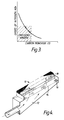
- Figure 1 illustrates the importance of "residence time” in the formation of NO x as calculated using the Zeldovich chain reaction model.
- "residence times" At a flame temperature of 3400 o F., "residence times" of 0.1, 0.7 and 4.5 seconds produce NO x levels of 100 ppmv, 1000 ppmv and equilibrium levels, respectively, all of which exceed proposed emissions standards.
- Pre-mix combustion systems also offer the advantage of a high heat release rate per unit of combustion volume as compared to nozzle mix systems. In other respects, they are inferior to nozzle mixing systems; particularly with respect to combustion stability limits. Beyond certain air to fuel ratio values, combustion moves away from the burner apparatus and the flame is extinguished. These effects are apparent in Figure 2, in which it can be seen that pre-mix burners have a limited stability range in the more useful fuel lean non-polluting operating range. Also, for all burner types, as the stability limits are approached, the combustion efficiency decreases prior to flame extinction or "blow-out". The reduction in combustion efficiency produces large amounts of unburned combustible pollutants, predominately CO in the case of natural gas combustion.
- Flame stabilization can be achieved by the use of a flame holding device or bluff body in the air/gas mixture stream. Typical flame stabilizing devices include metal screens, rods, and flame inserts. It has been found that these flame stabilizing devices also reduce NO x emissions. Radiant fiber and ceramic surface burners have also been used for similar reasons. In the foregoing cases, the rods or surfaces provide a heat absorbing mechanism capable of re-radiating the absorbed heat to an absorbing surface beyond the flame region.
- Burners of the type shown have been operated with port face loadings in the range of 5,000-100,000 BTU/hr ins2. Flame stabilization can also be achieved by aerodynamic means, e.g., opposed jet recirculation, wake flow, etc., eliminating the need for mechanical stabilizers.
- Figure 1 shows the theoretical concentration of NO x produced versus time and temperature as calculated using the Zeldovich chain reaction model.
- Figure 2 is a graph of Air/Fuel Ratio versus Blow-Off Velocity for nozzle mix burners and premix burners.
- Figure 3 is a graph of the Oxides of Nitrogen versus Combustibles, such as CO, and illustrates the "emissions window" in which burners are considered to be operating at acceptable emission levels.
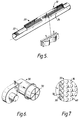
- Figure 4 is a cross-sectional view of one type of pre-mix burner utilizing external flame stabilization apparatus and which can be operated using the methodology of the present invention.
- Figure 5 is a cross-sectional view of another type of pre-mix burner utilizing external flame stabilization apparatus and which can be operated using the methodology of the present invention.
- Figure 6 is a cross-sectional view of still another type of pre-mix burner utilizing external flame stabilization apparatus and which can be operated using the methodology of the present invention.
- Figure 7 is an enlarged partial cross-sectional view of the distributor plate illustrated in Figure 6 and illustrates the configuration of the ports therein.
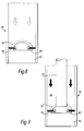
- Figure 8 is a cross-sectional view of one type of pre-mix burner utilizing internal flame stabilization apparatus and which can be operated using the methodology of the present invention.
- Figure 9 is a cross-sectional view of another type of pre-mix burner utilizing internal flame stabilization apparatus and which can be operated using the methodology of the present invention.
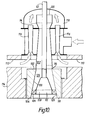
- Figure 10 is a cross-sectional view of still another type of pre-mix burner utilizing internal flame stabilization apparatus and which can be operated using the methodology of the present invention.
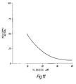
- Figure 11 is a graph of NO x Emissions versus Percent Excess Air.
- the production of NO x is a function of combustion temperature and the time required to complete combustion.
- the use of excess air in the air/gas mixture also decreases the production of NO x .
- the reduction in NO x production in this case can be attributed to a decrease in the temperature of combustion as a result of the excess air.
- an increase in the velocity of the air/gas mixture can be utilized to reduce NO x emissions. Such an increase in velocity can be achieved by reducing the size of the orifices through which the air/gas mixture flows or by increasing the port face loadings.
- the "residence time" associated with the formation of a flame is decreased, i.e., the combustion gases are in the reaction zone of the flame for a significantly shorter period of time which, in turn, reduces the production of NO x .
- the velocity of the air/gas mixture can only be increased to a level where the flame begins to "lift-off" the burner. An increase in the velocity of the air/gas mixture beyond the foregoing level results in the flame being blown out.
- a flame stabilizing device In order to increase the velocity of the air/gas mixture beyond the velocity where flame "lift-off” occurs, a flame stabilizing device must be utilized.
- FIG 4 is a view of one of a number of burner units 10 which utilizes a flame stabilizing device and which can be operated using the methodology of the present invention to produce a very low level of NO x emissions.
- the burner unit 10 includes a plenum 12 with a distribution plate 14 extending across its upper surface forming the outlet of the burner.
- the distribution plate 14 has a plurality of orifices or ports 16 passing therethrough.
- a flame arrester/distributor matrix 18 is positioned adjacent the upper surface of the distribution plate 14.
- burner unit 20 illustrated in Figure 5.
- Burner unit 20 includes a burner body 22 and a plurality of parallel flame arrester/distributor ribbons 24 adjacent its upper surface forming ports 26 therebetween.
- a still another embodiment of a burner unit which utilizes a flame stabilizing device and which can utilize the methodology of the present invention so as to produce a very low level of NO x emissions is burner unit 30 illustrated in Figure 6.
- Burner unit 30 includes a ceramic tile distributor plate 32 having a plurality of ports 34 therein as shown in Figure 7. Each port 34 has a through portion 36 of substantially constant diameter or may incorporate a tapered portion 38 of increasing diameter from its junction with through portion 36 to the outer surface 40 of the distributor plate 32.
- burner units are merely examples of some types of burners that can utilize the methodology of the present invention so as to produce very low levels of NO x emissions. Many other types of burners can be utilized with similar results and there are no restrictions as to burner size, shape, porting configuration, method of fabrication, or materials utilized for same.
- the plenum or burner body is connected to an air-gas supply. In this manner, a combustible mixture of air and gas is supplied to the plenum or burner body from the air-gas supply.
- one or more flame stabilizing devices are positioned a short distance above the ports in the burner units utilized.
- the flame stabilizing devices may include one or more ceramic flame rods, wire mesh flame screens, or any combination thereof, in order to stabilize the flame above the ports provided in the burner utilized. It should be noted that in addition to stabilizing the flame above the ports, the flame stabilizing devices may also produce radiant heat which further serves to suppress NO x formation.
- flame screens formed from 0.092 in. Nichrome or Inconel wire have been used successfully with various types of burners.
- the optimum distance between the flame stabilizing means and the top of the burner to minimize the production of NO x can be determined empirically or by experimentation.
- a bluff body 60 can be located within the outlet 62 of the burner, shown generally by the numeral 64, in Figure 8.
- the bluff body 60 can be formed from any of a variety of geometries, e.g., a weld cap having a generally semi-spherical configuration, or the like, which is held within the outlet 62 of the burner by means of set screws 66 which are threadably received through the bluff body 60 so that their ends contact the inner surface of the burner 64.
- Bluff body 60 is positioned within the outlet 62 so that the flow of the air/gas mixture contacts the convex surface of same.
- the bluff body 60 presents a contoured obstruction to the flow of the air/gas mixture.
- a separate pilot (not shown) is utilized to ignite the air/gas mixture and the velocity of the air/gas mixture approaches the velocity at which the flame begins to "lift-off" the surface defining the outlet 62 of the burner 64. It should be noted that flow of the air/gas mixture impinges upon the upstream face of the bluff body 60, and then recirculates counter to the air/gas flow direction in a zone on the downstream side of the bluff body creating a region which supports combustion before passing outwardly therefrom to the outlet 62 of the burner 64.
- FIG. 9 Another burner structure which incorporates flame stabilization is shown in Figure 9 and includes a bluff body 70 attached to the end of a pilot tube 72.
- the bluff body 70 can be formed from any of a variety of geometries, e.g., a weld cap having a generally semi-spherical configuration, or the like.
- the pilot tube 72 and the bluff body 70 can be formed from a pipe and a reducing coupling.
- the pilot tube 72 and bluff body 70 are received within the outlet 74 of the burner, shown generally by the numeral 76, and are held within same by means of set screws 78 which are threadably received through the bluff body 70 so that their ends contact the inner surface of the burner 76.
- the pilot tube 72 and the bluff body 70 are positioned within the burner 76 so as to be substantially concentric therein.
- the air/gas mixture passes through a passageway 80 between the outer surface of the pilot tube 72 and the inner surface of burner 76 and the mixture impinges upon the upstream face of the bluff body 70, and then recirculates counter to the air/gas flow direction in a zone on the downstream side of the bluff body 70 creating a region which supports combustion.
- the resulting combustion gases pass to the outlet 74 of the burner 76.
- the velocity of the air/gas mixture approaches the velocity at which the flame begins to "lift-off" the surface forming the outlet 74 of the burner 76. It has been found that the foregoing bluff bodies in Figures 8 and 9 provide flame stabilization, permitting the velocity of the air/gas mixture to be increased beyond the velocity at which flame "lift-off” would occur if a flame stabilizing device had not been used. It has also been found that the use of such bluff bodies negates the need for a flame stabilizing device exterior to the outlet of the burner.
- a still another burner structure which incorporates flame stabilization is shown in Figure 10 and includes a flameholder 90 attached to the end of a pilot tube 92.
- the flameholder 90 can be cup-shaped and acts as a bluff body, as in the structure shown in Figures 8 and 9.
- the pilot tube 92 is positioned within a pipe 94 so as to be substantially concentric therein.
- the circumferential end 96 of pipe 94 abuts a refractory diffuser 98 having a tapered opening 100 therein.
- the diameter of the tapered opening 100 increases from the inner surface 102 of the refractory diffuser 98 to the outer surface 104 thereof.
- the inner diameter of pipe 94 is approximately the same as the diameter of the tapered opening 100 at the inner surface 102 of the refractory diffuser 98.
- the pipe 94 is aligned with the tapered opening 100 so that no discontinuities exist between the surface defining the inner diameter of the pipe 94 and the surface defining the tapered opening 100 in the refractory diffuser 98.
- a swirl vane assembly 106 is positioned adjacent the outlet 108 of the flameholder 90 and is interposed between the flameholder 90 and the surface defining the tapered opening 100 in the refractory diffuser 98.
- Air and fuel are provided through apertures 110 and 112, respectively, in the burner housing 114 and pass through a plurality of mixing venturis 116 into a chamber 118 before passing into pipe 94 through end 120 thereof.
- the air/gas mixture passes through a passageway 122 between the inner surface of the pipe 94 and the outer surface of the pilot tube 92 into a passageway 124 between the surface defining the tapered opening 100 in the refractory diffuser 98 and the outer surface of the flameholder 90.
- the mixture recirculates counter to the air/gas flow direction in a zone on the downstream side of the flameholder 90 creating a region which supports combustion.
- the resulting combustion gases pass outwardly therefrom to the outlet 126 of the burner.
- the velocity of the air/gas mixture approaches the velocity at which the flame begins to "lift-off” the surface forming the outlet 126 of the burner.
- the flameholder 90 permits the velocity of the air/gas mixture to be increased beyond the velocity at which flame "lift-off” would occur if a flameholder had not been used.
- a flame stabilizing device increases the maximum flame extinction or "blow-out"" velocity of the air-gas mixture.
- the device may also act as a radiator of heat thus keeping the resulting temperature from exceeding the temperature at which a significant amount of NO x is produced. It should be noted, however, that flame stabilization can also be achieved by aerodynamic means, e.g., opposed jet recirculation, wake flows, etc., eliminating the need for a stabilizing device.
- Another feature of the present invention is that the resulting production of NO x and CO are within the "emissions window" shown in Figure 3.
- conventional burners typically produce NO x and CO in inverse proportions since time and temperature, both of which are conducive to NO x formation, are required to reduce CO to CO2.
- Test results using the methodology of the present invention i.e., 20% and greater excess air at a high velocity, reveal that even though extremely low levels of NO x are produced, approximately 20 ppmv, the production of CO is not excessive and is within the "emissions window".
- the methodology of the present invention minimizes the production of NO x while producing low levels of CO.
Landscapes
- Engineering & Computer Science (AREA)
- Chemical & Material Sciences (AREA)
- Combustion & Propulsion (AREA)
- Mechanical Engineering (AREA)
- General Engineering & Computer Science (AREA)
Applications Claiming Priority (2)
| Application Number | Priority Date | Filing Date | Title |
|---|---|---|---|
| US61458190A | 1990-11-16 | 1990-11-16 | |
| US614581 | 1990-11-16 |
Publications (3)
| Publication Number | Publication Date |
|---|---|
| EP0486169A2 true EP0486169A2 (de) | 1992-05-20 |
| EP0486169A3 EP0486169A3 (en) | 1992-12-16 |
| EP0486169B1 EP0486169B1 (de) | 1998-01-21 |
Family
ID=24461877
Family Applications (1)
| Application Number | Title | Priority Date | Filing Date |
|---|---|---|---|
| EP19910309796 Expired - Lifetime EP0486169B1 (de) | 1990-11-16 | 1991-10-23 | Brenner mit niedriger NOx-Produktion |
Country Status (4)
| Country | Link |
|---|---|
| EP (1) | EP0486169B1 (de) |
| JP (1) | JPH06317308A (de) |
| CA (1) | CA2054014C (de) |
| DE (1) | DE69128768D1 (de) |
Cited By (17)
| Publication number | Priority date | Publication date | Assignee | Title |
|---|---|---|---|---|
| WO1993013360A1 (en) * | 1991-12-30 | 1993-07-08 | Bowin Designs Pty. Ltd. | Gas-fired heaters with burners which operate without secondary air |
| WO1995009326A1 (en) * | 1993-09-28 | 1995-04-06 | Ingenieursburo P.I. Produkt Innovatie B.V. | Method and device for burning gas |
| US6846175B2 (en) | 2002-03-16 | 2005-01-25 | Exxonmobil Chemical Patents Inc. | Burner employing flue-gas recirculation system |
| US6866502B2 (en) | 2002-03-16 | 2005-03-15 | Exxonmobil Chemical Patents Inc. | Burner system employing flue gas recirculation |
| US6869277B2 (en) | 2002-03-16 | 2005-03-22 | Exxonmobil Chemical Patents Inc. | Burner employing cooled flue gas recirculation |
| US6877980B2 (en) | 2002-03-16 | 2005-04-12 | Exxonmobil Chemical Patents Inc. | Burner with low NOx emissions |
| US6881053B2 (en) | 2002-03-16 | 2005-04-19 | Exxonmobil Chemical Patents Inc. | Burner with high capacity venturi |
| US6884062B2 (en) | 2002-03-16 | 2005-04-26 | Exxonmobil Chemical Patents Inc. | Burner design for achieving higher rates of flue gas recirculation |
| US6887068B2 (en) | 2002-03-16 | 2005-05-03 | Exxonmobil Chemical Patents Inc. | Centering plate for burner |
| US6890171B2 (en) | 2002-03-16 | 2005-05-10 | Exxonmobil Chemical Patents, Inc. | Apparatus for optimizing burner performance |
| US6890172B2 (en) | 2002-03-16 | 2005-05-10 | Exxonmobil Chemical Patents Inc. | Burner with flue gas recirculation |
| US6893252B2 (en) | 2002-03-16 | 2005-05-17 | Exxonmobil Chemical Patents Inc. | Fuel spud for high temperature burners |
| US6893251B2 (en) | 2002-03-16 | 2005-05-17 | Exxon Mobil Chemical Patents Inc. | Burner design for reduced NOx emissions |
| US6986658B2 (en) | 2002-03-16 | 2006-01-17 | Exxonmobil Chemical Patents, Inc. | Burner employing steam injection |
| US7322818B2 (en) | 2002-03-16 | 2008-01-29 | Exxonmobil Chemical Patents Inc. | Method for adjusting pre-mix burners to reduce NOx emissions |
| US7476099B2 (en) | 2002-03-16 | 2009-01-13 | Exxonmobil Chemicals Patents Inc. | Removable light-off port plug for use in burners |
| CN117490064A (zh) * | 2023-12-05 | 2024-02-02 | 瓦兰热能设备(无锡)有限公司 | 一种低氮环保燃烧器燃烧头 |
Families Citing this family (1)
| Publication number | Priority date | Publication date | Assignee | Title |
|---|---|---|---|---|
| US9388983B2 (en) | 2013-10-03 | 2016-07-12 | Plum Combustion, Inc. | Low NOx burner with low pressure drop |
Family Cites Families (6)
| Publication number | Priority date | Publication date | Assignee | Title |
|---|---|---|---|---|
| FR2249583A5 (en) * | 1973-10-26 | 1975-05-23 | Gaz De France | Stable burner for gas torch - inner discharge ports give swirling flame inside main flame |
| GB2054822B (en) * | 1979-06-15 | 1983-04-07 | Urquhart Eng Co Ltd | Controlled combustion of gases |
| DE3042548A1 (de) * | 1980-11-12 | 1982-10-07 | Msk - Verpackungs-Systeme Gmbh, 4192 Kalkar | Brenner mit breitschlitzduese zur erzeugung eines heissgasstromes |
| DE3702415C1 (de) * | 1987-01-28 | 1988-04-21 | Babcock Werke Ag | Brenner |
| NL8900030A (nl) * | 1989-01-06 | 1990-08-01 | Remeha Fabrieken Bv | Nox-arme atmosferische gasbrander. |
| GB2231949A (en) * | 1989-05-26 | 1990-11-28 | Burco Dean Appliances Ltd | Gas burner |
-
1991
- 1991-10-23 CA CA 2054014 patent/CA2054014C/en not_active Expired - Fee Related
- 1991-10-23 EP EP19910309796 patent/EP0486169B1/de not_active Expired - Lifetime
- 1991-10-23 DE DE69128768T patent/DE69128768D1/de not_active Expired - Lifetime
- 1991-11-14 JP JP32510291A patent/JPH06317308A/ja not_active Withdrawn
Cited By (20)
| Publication number | Priority date | Publication date | Assignee | Title |
|---|---|---|---|---|
| WO1993013360A1 (en) * | 1991-12-30 | 1993-07-08 | Bowin Designs Pty. Ltd. | Gas-fired heaters with burners which operate without secondary air |
| WO1995009326A1 (en) * | 1993-09-28 | 1995-04-06 | Ingenieursburo P.I. Produkt Innovatie B.V. | Method and device for burning gas |
| NL9301980A (nl) * | 1993-09-28 | 1995-04-18 | Ingbureaup I Product Innovatie | Werkwijze en inrichting voor het verbranden van gas. |
| US6846175B2 (en) | 2002-03-16 | 2005-01-25 | Exxonmobil Chemical Patents Inc. | Burner employing flue-gas recirculation system |
| US6866502B2 (en) | 2002-03-16 | 2005-03-15 | Exxonmobil Chemical Patents Inc. | Burner system employing flue gas recirculation |
| US6869277B2 (en) | 2002-03-16 | 2005-03-22 | Exxonmobil Chemical Patents Inc. | Burner employing cooled flue gas recirculation |
| US6877980B2 (en) | 2002-03-16 | 2005-04-12 | Exxonmobil Chemical Patents Inc. | Burner with low NOx emissions |
| US6881053B2 (en) | 2002-03-16 | 2005-04-19 | Exxonmobil Chemical Patents Inc. | Burner with high capacity venturi |
| US6884062B2 (en) | 2002-03-16 | 2005-04-26 | Exxonmobil Chemical Patents Inc. | Burner design for achieving higher rates of flue gas recirculation |
| US6887068B2 (en) | 2002-03-16 | 2005-05-03 | Exxonmobil Chemical Patents Inc. | Centering plate for burner |
| US6890171B2 (en) | 2002-03-16 | 2005-05-10 | Exxonmobil Chemical Patents, Inc. | Apparatus for optimizing burner performance |
| US6890172B2 (en) | 2002-03-16 | 2005-05-10 | Exxonmobil Chemical Patents Inc. | Burner with flue gas recirculation |
| US6893252B2 (en) | 2002-03-16 | 2005-05-17 | Exxonmobil Chemical Patents Inc. | Fuel spud for high temperature burners |
| US6893251B2 (en) | 2002-03-16 | 2005-05-17 | Exxon Mobil Chemical Patents Inc. | Burner design for reduced NOx emissions |
| US6902390B2 (en) | 2002-03-16 | 2005-06-07 | Exxonmobil Chemical Patents, Inc. | Burner tip for pre-mix burners |
| US6986658B2 (en) | 2002-03-16 | 2006-01-17 | Exxonmobil Chemical Patents, Inc. | Burner employing steam injection |
| US7025587B2 (en) | 2002-03-16 | 2006-04-11 | Exxonmobil Chemical Patents Inc. | Burner with high capacity venturi |
| US7322818B2 (en) | 2002-03-16 | 2008-01-29 | Exxonmobil Chemical Patents Inc. | Method for adjusting pre-mix burners to reduce NOx emissions |
| US7476099B2 (en) | 2002-03-16 | 2009-01-13 | Exxonmobil Chemicals Patents Inc. | Removable light-off port plug for use in burners |
| CN117490064A (zh) * | 2023-12-05 | 2024-02-02 | 瓦兰热能设备(无锡)有限公司 | 一种低氮环保燃烧器燃烧头 |
Also Published As
| Publication number | Publication date |
|---|---|
| CA2054014A1 (en) | 1992-05-17 |
| JPH06317308A (ja) | 1994-11-15 |
| DE69128768D1 (de) | 1998-02-26 |
| EP0486169A3 (en) | 1992-12-16 |
| CA2054014C (en) | 1998-01-20 |
| EP0486169B1 (de) | 1998-01-21 |
Similar Documents
| Publication | Publication Date | Title |
|---|---|---|
| US5236327A (en) | Low NOx burner | |
| EP0486169B1 (de) | Brenner mit niedriger NOx-Produktion | |
| CA2632012C (en) | Method and apparatus for reducing nox emissions in a gas burner | |
| US5256058A (en) | Method and apparatus for oxy-fuel heating with lowered NOx in high temperature corrosive environments | |
| US4928481A (en) | Staged low NOx premix gas turbine combustor | |
| KR970009487B1 (ko) | 공기-연료 혼합물의 연소중에 발생되는 질소산화물 발생량의 감소 방법 | |
| US5667374A (en) | Premix single stage low NOx burner | |
| US4505666A (en) | Staged fuel and air for low NOx burner | |
| US7175423B1 (en) | Air staged low-NOx burner | |
| EP0782681B1 (de) | Brenner mit sehr niedrigem nox-ausstoss | |
| US5078064A (en) | Apparatus and method of lowering NOx emissions using diffusion processes | |
| US5013236A (en) | Ultra-low pollutant emission combustion process and apparatus | |
| EP0479414A1 (de) | Brenner mit geringer NOX-Produktion | |
| EP0575043B1 (de) | Verbrennungsverfahren und Brennervorrichtung | |
| US5080577A (en) | Combustion method and apparatus for staged combustion within porous matrix elements | |
| US20080280238A1 (en) | Low swirl injector and method for low-nox combustor | |
| US5551869A (en) | Gas staged burner | |
| EP0076036B1 (de) | Verfahren und Vorrichtung zum Verbrennen von Brennstoff in Stufen | |
| US20090087802A1 (en) | Removable Light-Off Port Plug for Use in Burners | |
| US5681159A (en) | Process and apparatus for low NOx staged-air combustion | |
| US20240167679A1 (en) | Combustion system with mixing and flame arresting for pollution reduction | |
| US5516280A (en) | Apparatus and method for burning a lean, premixed fuel/air mixture with low NOx emission | |
| JP2619973B2 (ja) | 超低量汚染物質排出燃焼法および装置 | |
| EP0210313A1 (de) | Verfahren und Apparat zum Verbrennen von Brennstoff |
Legal Events
| Date | Code | Title | Description |
|---|---|---|---|
| PUAI | Public reference made under article 153(3) epc to a published international application that has entered the european phase |
Free format text: ORIGINAL CODE: 0009012 |
|
| AK | Designated contracting states |
Kind code of ref document: A2 Designated state(s): BE DE ES FR GB IT |
|
| PUAL | Search report despatched |
Free format text: ORIGINAL CODE: 0009013 |
|
| AK | Designated contracting states |
Kind code of ref document: A3 Designated state(s): BE DE ES FR GB IT |
|
| 17P | Request for examination filed |
Effective date: 19930611 |
|
| 17Q | First examination report despatched |
Effective date: 19940527 |
|
| GRAG | Despatch of communication of intention to grant |
Free format text: ORIGINAL CODE: EPIDOS AGRA |
|
| GRAH | Despatch of communication of intention to grant a patent |
Free format text: ORIGINAL CODE: EPIDOS IGRA |
|
| GRAH | Despatch of communication of intention to grant a patent |
Free format text: ORIGINAL CODE: EPIDOS IGRA |
|
| GRAA | (expected) grant |
Free format text: ORIGINAL CODE: 0009210 |
|
| RAP1 | Party data changed (applicant data changed or rights of an application transferred) |
Owner name: ENERGY INTERNATIONAL, INC. |
|
| AK | Designated contracting states |
Kind code of ref document: B1 Designated state(s): BE DE ES FR GB IT |
|
| PG25 | Lapsed in a contracting state [announced via postgrant information from national office to epo] |
Ref country code: IT Free format text: LAPSE BECAUSE OF FAILURE TO SUBMIT A TRANSLATION OF THE DESCRIPTION OR TO PAY THE FEE WITHIN THE PRE;WARNING: LAPSES OF ITALIAN PATENTS WITH EFFECTIVE DATE BEFORE 2007 MAY HAVE OCCURRED AT ANY TIME BEFORE 2007. THE CORRECT EFFECTIVE DATE MAY BE DIFFERENT FROM THE ONE RECORDED.SCRIBED TIME-LIMIT Effective date: 19980121 Ref country code: BE Free format text: LAPSE BECAUSE OF FAILURE TO SUBMIT A TRANSLATION OF THE DESCRIPTION OR TO PAY THE FEE WITHIN THE PRESCRIBED TIME-LIMIT Effective date: 19980121 Ref country code: FR Free format text: LAPSE BECAUSE OF FAILURE TO SUBMIT A TRANSLATION OF THE DESCRIPTION OR TO PAY THE FEE WITHIN THE PRESCRIBED TIME-LIMIT Effective date: 19980121 Ref country code: ES Free format text: THE PATENT HAS BEEN ANNULLED BY A DECISION OF A NATIONAL AUTHORITY Effective date: 19980121 |
|
| REF | Corresponds to: |
Ref document number: 69128768 Country of ref document: DE Date of ref document: 19980226 |
|
| PG25 | Lapsed in a contracting state [announced via postgrant information from national office to epo] |
Ref country code: DE Free format text: LAPSE BECAUSE OF FAILURE TO SUBMIT A TRANSLATION OF THE DESCRIPTION OR TO PAY THE FEE WITHIN THE PRESCRIBED TIME-LIMIT Effective date: 19980422 |
|
| EN | Fr: translation not filed | ||
| PGFP | Annual fee paid to national office [announced via postgrant information from national office to epo] |
Ref country code: GB Payment date: 19981014 Year of fee payment: 8 |
|
| PLBE | No opposition filed within time limit |
Free format text: ORIGINAL CODE: 0009261 |
|
| STAA | Information on the status of an ep patent application or granted ep patent |
Free format text: STATUS: NO OPPOSITION FILED WITHIN TIME LIMIT |
|
| 26N | No opposition filed | ||
| PG25 | Lapsed in a contracting state [announced via postgrant information from national office to epo] |
Ref country code: GB Free format text: LAPSE BECAUSE OF NON-PAYMENT OF DUE FEES Effective date: 19991023 |
|
| GBPC | Gb: european patent ceased through non-payment of renewal fee |
Effective date: 19991023 |