EP0485846A2 - Sheet-stapling device - Google Patents
Sheet-stapling device Download PDFInfo
- Publication number
- EP0485846A2 EP0485846A2 EP91118759A EP91118759A EP0485846A2 EP 0485846 A2 EP0485846 A2 EP 0485846A2 EP 91118759 A EP91118759 A EP 91118759A EP 91118759 A EP91118759 A EP 91118759A EP 0485846 A2 EP0485846 A2 EP 0485846A2
- Authority
- EP
- European Patent Office
- Prior art keywords
- stapling
- driving element
- stapling head
- head
- stapling device
- Prior art date
- Legal status (The legal status is an assumption and is not a legal conclusion. Google has not performed a legal analysis and makes no representation as to the accuracy of the status listed.)
- Granted
Links
Images

Classifications
-
- B—PERFORMING OPERATIONS; TRANSPORTING
- B27—WORKING OR PRESERVING WOOD OR SIMILAR MATERIAL; NAILING OR STAPLING MACHINES IN GENERAL
- B27F—DOVETAILED WORK; TENONS; SLOTTING MACHINES FOR WOOD OR SIMILAR MATERIAL; NAILING OR STAPLING MACHINES
- B27F7/00—Nailing or stapling; Nailed or stapled work
- B27F7/17—Stapling machines
-
- B—PERFORMING OPERATIONS; TRANSPORTING
- B27—WORKING OR PRESERVING WOOD OR SIMILAR MATERIAL; NAILING OR STAPLING MACHINES IN GENERAL
- B27F—DOVETAILED WORK; TENONS; SLOTTING MACHINES FOR WOOD OR SIMILAR MATERIAL; NAILING OR STAPLING MACHINES
- B27F7/00—Nailing or stapling; Nailed or stapled work
- B27F7/006—Nailing or stapling machines provided with means for operating on discrete points
Definitions
- the invention relates to a stapling device for connecting by means of staples sheets arranged in a stack, said device comprising a driving element and a stapling head which can be actuated by said driving element and is movable into contact with an anvil.
- the invention moreover relates to a stapling device for connecting by means of staples sheets arranged in a stack, said device comprising a driving element and a stapling head, which can be actuated by said element and is movable into contact with an anvil, and being adjustable to a plurality of selectable stapling positions.
- this object is attained in that the stapling head and the driving element are connected by a releasable coupling.
- the stapling head and the driving element are shiftable on a common housing, with the stapling head being guided in a guide groove open towards the anvil so that it can be removed.
- the coupling is designed as a coupling slider which is guided under spring load on the driving element and is held in positive engagement with entrainment members of the stapling head.
- the stapling device is shiftably guided on a guide rod so as to be adjustable to various stapling positions, and the driving element is engaged by a polygonal driving shaft connected positively therewith.
- the stapling head includes all functional parts required for transporting, separating, folding and driving in of wire sections formed into staples which are stored in the form of a wire strip in an exchangeable magazine.
- the stapling head can be simply and rapidly exchanged in the case of malfunctioning.
- the defective stapling head has been removed, it can be examined from all sides outside the system and repaired if necessary while the stapling device can immediately continue operation with a freshly exchanged stapling head.
- the stapling device according to the invention is arranged on a finishing unit of a type known per se and not illustrated, in which sheets fed individually, in particular copy sheets dispensed by a copier, are collected in a collecting station 9 and combined in sets by means of staples.
- the stapling device is mounted as a complete assembly unit in or on two cup-shaped plastic housing portions 13 and 14 which are connected by a plurality of support legs 13c and 14b respectively which are screwed together and held in positive engagement (only two support legs have reference numerals).
- the stapling head 1 has a housing 1a in which a commercially available stapling head of a type known per se with an exchangeable magazine 12 is mounted, which comprises all functional elements required for transporting, separating, folding and driving in of wire sections formed into staples which are stored in the form of a wire strip in magazine 12.
- An actuating member 10 of stapling head 1 comprises a pressure bolt 11 which is engaged by the upper side 3e of a bracket 3 of a driving element generally denoted 2.
- the U-shaped bracket 3 surrounds and positively engages a cam 4 which is mounted for rotation on bearings 16 arranged on either side and positively connected with said cam.
- the bracket 3 is provided with openings 3c arranged on either side and receiving the bearings 16 which allow the bracket 3 to move in the direction of the arrow "A".
- the bearings 16 which extend beyond the bracket 3 on either side are mounted for rotation in the housing portions 13 and 14 as can be seen from Fig. 2.
- the bracket 3 is guided on the housing portions 13 and 14 by guide webs 3b and 3f which are arranged on either side and guided for movement in the direction of the arrow "A" in correspondingly disposed guide grooves 13b (of which only one is illustrated).
- a coupling slider 6 which positively engages entrainment members 1d projecting from either side of the actuating member 10 of stapling head 1 are shiftably mounted on bracket 3.
- Coupling slider 6 is biased into the coupling position illustrated by springs 17, which are supported on wall sections 3a of bracket 3, and can be moved in the direction of the arrow "C" in opposition to springs 17 in that a handling means 6a is operated. Inclined portions 6b on coupling slider 6 allow the stapling head 1 to be automatically locked during insertion in a manner to be described further below.
- the stapling head 1 is guided on the housing portions 13 and 14 by guide webs 1c which are arranged on arms 1b molded on either side of housing 1a and, as shown in Fig. 2, engaging guide grooves 13a, 14a which are open at the top.
- the entire stapling device mounted on the housing portions 13, 14 is guided for shifting movement along a polygonal driving shaft 5 and a guide rod 15 and adjustable to several selectable stapling positions.
- the polygonal driving shaft 5 is rotated by a drive unit not illustrated and positively engages the correspondingly designed bearings 16. Since the stapling device is permanently held in positive engagement with the polygonal driving shaft 5 it is immediately ready to function in any of its stapling positions.
- a collecting station 9 disposed above stapling head 1 accommodates the sheet stack 8 which is to be stapled.
- an anvil plate 7 is arranged which in a manner known per se serves for folding over and clinching the staple ends projecting from the sheet stack 8.
- the stationary anvil plate 7 which comprises a plurality of anvils 18 of a type known per se which are associated with the selectable stapling positions is fixed in the position shown in Figs. 1 and 2 by means of easily releasable attachment elements (not illustrated). In order that the stapling head 1 can be exchanged the anvil plate 7 can be removed from the path of movement of the stapling head 1 (not illustrated) after release of the attachment elements.
- the stapling device functions as follows: In order to assume the desired stapling position, the stapling head 1 is shifted along the guide rod 15 and the polygonal driving shaft 5 either by a drive or manually and is thus brought to the desired stapling position in which it is arrested (not illustrated).
- the stapling operation is started in that the polygonal driving shaft 5 is rotated clockwise and the cam 4 is thus rotated out of its initial position illustrated in Fig. 1.
- cam 4 moves bracket 3 upwards in the direction of the arrow "A” (see Fig. 1).
- the actuating member 10 which rests against the upper side 3e of bracket 3, is moved upwards in the direction of the arrow "B".
- the stapling head 1 approaches the sheet stack 8 to be stapled, and the sheet stack is placed on the anvil 18.
- a wire section is separated in a manner known per se and not illustrated from the wire strip, folded to form a staple and driven into the sheet stack 8 from below.
- the staple ends projecting from the top of sheet stack 8 are folded over in a known manner on anvil 18 and clinched on the sheet stack 8.
- the entire stapling device 1, 2 Upon termination of the stapling operation the entire stapling device 1, 2 is returned to its initial position shown in Fig. 1 by the cam 4 further rotating clockwise and by the coupling slider 6. During such return movement the wire strip is advanced in a known manner not illustrated so that a new stapling wire section is brought into its operative position.
Abstract
Description
- The invention relates to a stapling device for connecting by means of staples sheets arranged in a stack, said device comprising a driving element and a stapling head which can be actuated by said driving element and is movable into contact with an anvil.
- The invention moreover relates to a stapling device for connecting by means of staples sheets arranged in a stack, said device comprising a driving element and a stapling head, which can be actuated by said element and is movable into contact with an anvil, and being adjustable to a plurality of selectable stapling positions.
- By a publication in Research Disclosure No. 15 710 of May 1977 a stapling device of a finishing unit of a copier has been disclosed which is guided on guide rods and can be adjusted to a plurality of selectable stapling positions. If the stapling head does not function properly, for example because a deformed staple has jammed, the device has to be disassembled in a time-consuming manner in order to repair the stapling device outside the unit.
- In order to eliminate jamming it is also known (DE-33 14 986-A) for part of the stapling head of a desktop stapling device to be designed as a pivotable element. However, in the case of such a device the cause of the jamming cannot be determined because the corresponding functional elements are hidden and are not visible from outside. If functional elements are damaged, therefore, jamming may recur and attempts at eliminating the damage will fail so that the stapling device becomes unusable.
- In the case of both of these known stapling devices repeated jamming in the stapling head results in long close-down periods of the stapling device.
- In particular if the stapling device is held in engagement with driving and guide means which allow adjustment to a plurality of stapling positions, exchanging or repairing a defective stapling device takes a lot of time during which the stapling device is out of use.
- It is the object of the invention to design a device of the generic type such that the stapling head can be exchanged rapidly and without difficulty in the case of malfunctioning.
- According to the invention this object is attained in that the stapling head and the driving element are connected by a releasable coupling.
- According to an advantageous modification of the invention, the stapling head and the driving element are shiftable on a common housing, with the stapling head being guided in a guide groove open towards the anvil so that it can be removed.
- According to a preferred modification of the invention the coupling is designed as a coupling slider which is guided under spring load on the driving element and is held in positive engagement with entrainment members of the stapling head.
- According to a particularly advantageous modification of the invention the stapling device is shiftably guided on a guide rod so as to be adjustable to various stapling positions, and the driving element is engaged by a polygonal driving shaft connected positively therewith.
- Advantageously the stapling head includes all functional parts required for transporting, separating, folding and driving in of wire sections formed into staples which are stored in the form of a wire strip in an exchangeable magazine.
- Thanks to the design and association of stapling head and driving elements according to the invention the stapling head can be simply and rapidly exchanged in the case of malfunctioning. When the defective stapling head has been removed, it can be examined from all sides outside the system and repaired if necessary while the stapling device can immediately continue operation with a freshly exchanged stapling head.
- Further features and advantages can be inferred from the description of an embodiment of the invention illustrated in the drawing and from the subclaims. The drawing shows schematically in
- Fig. 1
- a lateral view of the device in its initial position, without the housing, and
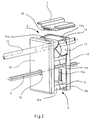
- Fig. 2
- an oblique view at a slightly smaller scale of the device according to Fig. 1 with the housing and the guide means.
- The stapling device according to the invention is arranged on a finishing unit of a type known per se and not illustrated, in which sheets fed individually, in particular copy sheets dispensed by a copier, are collected in a
collecting station 9 and combined in sets by means of staples. - The stapling device is mounted as a complete assembly unit in or on two cup-shaped
plastic housing portions support legs 13c and 14b respectively which are screwed together and held in positive engagement (only two support legs have reference numerals). - The
stapling head 1 has ahousing 1a in which a commercially available stapling head of a type known per se with anexchangeable magazine 12 is mounted, which comprises all functional elements required for transporting, separating, folding and driving in of wire sections formed into staples which are stored in the form of a wire strip inmagazine 12. - An actuating
member 10 ofstapling head 1 comprises apressure bolt 11 which is engaged by the upper side 3e of abracket 3 of a driving element generally denoted 2. The U-shapedbracket 3 surrounds and positively engages acam 4 which is mounted for rotation onbearings 16 arranged on either side and positively connected with said cam. Thebracket 3 is provided with openings 3c arranged on either side and receiving thebearings 16 which allow thebracket 3 to move in the direction of the arrow "A". Thebearings 16 which extend beyond thebracket 3 on either side are mounted for rotation in thehousing portions - The
bracket 3 is guided on thehousing portions guide grooves 13b (of which only one is illustrated). - A
coupling slider 6 which positively engagesentrainment members 1d projecting from either side of the actuatingmember 10 ofstapling head 1 are shiftably mounted onbracket 3. -
Coupling slider 6 is biased into the coupling position illustrated bysprings 17, which are supported on wall sections 3a ofbracket 3, and can be moved in the direction of the arrow "C" in opposition tosprings 17 in that a handling means 6a is operated. Inclinedportions 6b oncoupling slider 6 allow thestapling head 1 to be automatically locked during insertion in a manner to be described further below. - The
stapling head 1 is guided on thehousing portions arms 1b molded on either side ofhousing 1a and, as shown in Fig. 2, engaging guide grooves 13a, 14a which are open at the top. - The entire stapling device mounted on the
housing portions polygonal driving shaft 5 and aguide rod 15 and adjustable to several selectable stapling positions. Thepolygonal driving shaft 5 is rotated by a drive unit not illustrated and positively engages the correspondingly designedbearings 16. Since the stapling device is permanently held in positive engagement with thepolygonal driving shaft 5 it is immediately ready to function in any of its stapling positions. - A
collecting station 9 disposed abovestapling head 1 accommodates thesheet stack 8 which is to be stapled. Abovesheet stack 8 andopposite stapling head 1, ananvil plate 7 is arranged which in a manner known per se serves for folding over and clinching the staple ends projecting from thesheet stack 8. Thestationary anvil plate 7 which comprises a plurality ofanvils 18 of a type known per se which are associated with the selectable stapling positions is fixed in the position shown in Figs. 1 and 2 by means of easily releasable attachment elements (not illustrated). In order that thestapling head 1 can be exchanged theanvil plate 7 can be removed from the path of movement of the stapling head 1 (not illustrated) after release of the attachment elements. - The stapling device functions as follows:
In order to assume the desired stapling position, thestapling head 1 is shifted along theguide rod 15 and thepolygonal driving shaft 5 either by a drive or manually and is thus brought to the desired stapling position in which it is arrested (not illustrated). - The stapling operation is started in that the
polygonal driving shaft 5 is rotated clockwise and thecam 4 is thus rotated out of its initial position illustrated in Fig. 1. Duringsuch movement cam 4 movesbracket 3 upwards in the direction of the arrow "A" (see Fig. 1). At the same time the actuatingmember 10, which rests against the upper side 3e ofbracket 3, is moved upwards in the direction of the arrow "B". During such upward movement thestapling head 1 approaches thesheet stack 8 to be stapled, and the sheet stack is placed on theanvil 18. During further movement of the actuating member 10 a wire section is separated in a manner known per se and not illustrated from the wire strip, folded to form a staple and driven into thesheet stack 8 from below. The staple ends projecting from the top ofsheet stack 8 are folded over in a known manner onanvil 18 and clinched on thesheet stack 8. - Upon termination of the stapling operation the
entire stapling device cam 4 further rotating clockwise and by thecoupling slider 6. During such return movement the wire strip is advanced in a known manner not illustrated so that a new stapling wire section is brought into its operative position. - If the mechanism of the stapling head 1 jams during stapling the
anvil plate 7 is removed while the drive is shut down and thecoupling slider 6 then moved in the direction of the arrow "C" by the handling means 6a whereby theentrainment members 1d of theactuator 10 are released. With thecoupling slider 6 extracted,stapling head 1 is lifted as a complete assembly unit in the direction "B" from the open guide grooves 13a, 14a of thehousing portions - Now one simple operation is enough to shift a new, properly functioning
stapling head 1 in the reverse order into thehousing entrainment members 1d urging thecoupling slider 6 aside via theinclined portions 6b and in opposition to the force ofspring 17 until they lock on thecoupling slider 6 under the action of spring force. When theanvil plate 7 has been attached again the stapling device is immediately ready for use.
Claims (8)
- Stapling device for connecting by means of staples sheets arranged in a stack said device comprising a driving element and a stapling head which can be actuated by said driving element and is movable into contact with an anvil, characterized in that the stapling head (1) and the driving element (2) are connected by means of a releasable coupling (6).
- Stapling device for connecting by means of staples sheets arranged in a stack said device comprising a driving element and a stapling head which can be actuated by said driving element and is movable into contact with an anvil, and being adjustable to a plurality of selectable stapling positions, characterized in that the stapling head (1) and the driving element (2) are connected by means of a releasable coupling (6).
- Stapling device according to claim 1 or 2, characterized in that the stapling head (1) and the driving element (2) are guided for shifting movement in the stapling direction on a common housing (13, 14) and in that the stapling head (1) is positively connected with the driving element (2) by a coupling (6) which is movable transversely to its shifting direction.
- Stapling device according to claim 3, characterized in that the coupling is designed as a coupling slider (6) which is spring-biased, guided for shifting movement on the driving element (2) and held in engagement with at least one entrainment member (1d) of the stapling head (1).
- Stapling device according to one or several of claims 1 to 4, characterized in that guide webs (1c) are arranged on the stapling head (1), said webs extending in parallel with the direction of stapling and positively engaging guide grooves (13a, 14a) which are open towards the anvil (18) and provided on housing (13, 14).
- Stapling device according to one or several of claims 2 to 5, characterized in that the driving element (2, 4, 16) is held in positive and shiftable engagement with a polygonal driving shaft (5) and in that the housing (13, 14) is shiftably guided along a guide rod (15).
- Stapling device according to one or several of claims 1 to 6, characterized in that the driving element (2) comprises a cam (4) which is positively and shiftably connected with the polygonal driving shaft (5) and which positively engages a U-shaped bracket (3) shiftably guided on housing (13, 14).
- Stapling device according to one or several of claims 1 to 7, characterized in that the stapling head (1) comprises in a manner known per se both an exchangeable magazine (12) with a stock of stapling wire sections in the form of a wire strip as well as all functional parts required for transporting, separating, folding and driving in of a stapling wire section folded to form a staple.
Applications Claiming Priority (2)
| Application Number | Priority Date | Filing Date | Title |
|---|---|---|---|
| DE4035869 | 1990-11-10 | ||
| DE4035869A DE4035869A1 (en) | 1990-11-10 | 1990-11-10 | STAPLE FOR STAPLING LEAFS |
Publications (3)
| Publication Number | Publication Date |
|---|---|
| EP0485846A2 true EP0485846A2 (en) | 1992-05-20 |
| EP0485846A3 EP0485846A3 (en) | 1992-12-02 |
| EP0485846B1 EP0485846B1 (en) | 1995-09-13 |
Family
ID=6418054
Family Applications (1)
| Application Number | Title | Priority Date | Filing Date |
|---|---|---|---|
| EP91118759A Expired - Lifetime EP0485846B1 (en) | 1990-11-10 | 1991-11-04 | Sheet-stapling device |
Country Status (4)
| Country | Link |
|---|---|
| US (1) | US5181643A (en) |
| EP (1) | EP0485846B1 (en) |
| JP (1) | JPH04284295A (en) |
| DE (2) | DE4035869A1 (en) |
Cited By (2)
| Publication number | Priority date | Publication date | Assignee | Title |
|---|---|---|---|---|
| EP0605888A1 (en) * | 1992-12-29 | 1994-07-13 | Max Co., Ltd. | A stapler with improved stapling precision |
| EP0612594A1 (en) * | 1993-02-10 | 1994-08-31 | Max Co., Ltd. | A motor-driven stapler |
Families Citing this family (6)
| Publication number | Priority date | Publication date | Assignee | Title |
|---|---|---|---|---|
| DE4101391C2 (en) * | 1991-01-18 | 1995-08-10 | Kodak Ag | Stapling device for sheets |
| EP0579118B1 (en) * | 1992-07-10 | 1995-09-27 | Max Co., Ltd. | A motor driven stapler |
| JP2000084903A (en) * | 1998-09-11 | 2000-03-28 | Minolta Co Ltd | Stapling device |
| US6543663B1 (en) * | 1999-11-03 | 2003-04-08 | David M. Davis | Automatic fastening scheduler |
| US6641024B2 (en) * | 2000-02-08 | 2003-11-04 | Nisca Corporation | Stapling device |
| JP4748293B2 (en) * | 2001-09-11 | 2011-08-17 | マックス株式会社 | Built-in stapler |
Citations (3)
| Publication number | Priority date | Publication date | Assignee | Title |
|---|---|---|---|---|
| DE1121026B (en) * | 1956-12-29 | 1962-01-04 | Th Speckboetel Fa | Multi-head wire stitching machine |
| DE9004751U1 (en) * | 1990-04-26 | 1990-06-21 | Regitar Power Tools Co., Ltd., Taya Hsiang, Taichung, Tw | |
| AU668366B2 (en) * | 1991-10-02 | 1996-05-02 | Teledirect International, Inc. | Method and apparatus for automatic telephone scheduling system |
Family Cites Families (6)
| Publication number | Priority date | Publication date | Assignee | Title |
|---|---|---|---|---|
| US3514027A (en) * | 1967-12-06 | 1970-05-26 | Miehle Goss Dexter Inc | Wire stitching apparatus |
| DE2755210C3 (en) * | 1977-12-10 | 1982-01-07 | Koenig & Bauer AG, 8700 Würzburg | Staple locking device |
| JPS62236684A (en) * | 1986-04-08 | 1987-10-16 | 丸善株式会社 | Electric stapler |
| DE3855380T2 (en) * | 1987-12-28 | 1996-11-07 | Max Co Ltd | Anvil plate |
| US4913332A (en) * | 1989-01-23 | 1990-04-03 | Swingline Inc. | Sheath release device for stapler |
| US5076483A (en) * | 1990-10-23 | 1991-12-31 | Swingline Inc. | Housing mounted powered stapler for stapling variable stack |
-
1990
- 1990-11-10 DE DE4035869A patent/DE4035869A1/en not_active Withdrawn
-
1991
- 1991-10-21 US US07/779,771 patent/US5181643A/en not_active Expired - Lifetime
- 1991-11-04 EP EP91118759A patent/EP0485846B1/en not_active Expired - Lifetime
- 1991-11-04 DE DE69112995T patent/DE69112995T2/en not_active Expired - Fee Related
- 1991-11-11 JP JP3294241A patent/JPH04284295A/en active Pending
Patent Citations (3)
| Publication number | Priority date | Publication date | Assignee | Title |
|---|---|---|---|---|
| DE1121026B (en) * | 1956-12-29 | 1962-01-04 | Th Speckboetel Fa | Multi-head wire stitching machine |
| DE9004751U1 (en) * | 1990-04-26 | 1990-06-21 | Regitar Power Tools Co., Ltd., Taya Hsiang, Taichung, Tw | |
| AU668366B2 (en) * | 1991-10-02 | 1996-05-02 | Teledirect International, Inc. | Method and apparatus for automatic telephone scheduling system |
Non-Patent Citations (1)
| Title |
|---|
| RESEARCH DISCLOSURE vol. 15710, May 1977, pages 22 - 23 RUSSEL & HARTMAN 'STAPLE SENSING APPARATUS' * |
Cited By (4)
| Publication number | Priority date | Publication date | Assignee | Title |
|---|---|---|---|---|
| EP0605888A1 (en) * | 1992-12-29 | 1994-07-13 | Max Co., Ltd. | A stapler with improved stapling precision |
| US5460314A (en) * | 1992-12-29 | 1995-10-24 | Max Co., Ltd. | Stapler with improved stapling precision |
| EP0612594A1 (en) * | 1993-02-10 | 1994-08-31 | Max Co., Ltd. | A motor-driven stapler |
| US5791548A (en) * | 1993-02-10 | 1998-08-11 | The Max Co., Ltd. | Motor driven stapler |
Also Published As
| Publication number | Publication date |
|---|---|
| US5181643A (en) | 1993-01-26 |
| DE69112995T2 (en) | 1996-05-15 |
| DE4035869A1 (en) | 1992-05-14 |
| DE69112995D1 (en) | 1995-10-19 |
| JPH04284295A (en) | 1992-10-08 |
| EP0485846A3 (en) | 1992-12-02 |
| EP0485846B1 (en) | 1995-09-13 |
Similar Documents
| Publication | Publication Date | Title |
|---|---|---|
| EP0530857B1 (en) | Clincher | |
| US4378085A (en) | Stapler apparatus having a mechanism for bending and cutting staple legs in accordance with the thickness of the work piece | |
| US20080054044A1 (en) | Stapler | |
| WO1994000277A1 (en) | Stapler having a clinching mechanism | |
| EP0485846B1 (en) | Sheet-stapling device | |
| EP1711314B1 (en) | Stapler | |
| US3994427A (en) | Automatic sheet jogging and stapling machine | |
| EP1053080B1 (en) | Stapler with internal guidance of the legs of a staple | |
| EP0807499A2 (en) | Electric stapler | |
| US5673816A (en) | Roofing washer magazine for barbed roofing washers | |
| JPS5986551A (en) | Sorter equipped with staple device | |
| US6637635B2 (en) | Clinching mechanism for staplers | |
| US6568669B2 (en) | Sheet post-processing apparatus | |
| EP0521122B1 (en) | Stitching and folding sheets of material | |
| US6561504B2 (en) | Finisher with single roller for frictionally moving each sheet | |
| US6616029B1 (en) | Stapler with reversible electric motor | |
| US5236185A (en) | Sheet distributing system | |
| US4515356A (en) | Spring biased crank arm drive for tray mounted stapler | |
| US6547238B2 (en) | Sheet beam breaker | |
| WO2002098613A2 (en) | Stapler cartridge and stapler apparatus comprising the same | |
| JPH0640181A (en) | Method and device for stapling a plurality of paper sheaves | |
| US4932579A (en) | Stapling apparatus with stack joggers | |
| JP3499288B2 (en) | Sheet post-processing equipment | |
| WO2005002799A1 (en) | Electrically driven stapler | |
| US6619528B2 (en) | Cartridge for housing staples |
Legal Events
| Date | Code | Title | Description |
|---|---|---|---|
| PUAI | Public reference made under article 153(3) epc to a published international application that has entered the european phase |
Free format text: ORIGINAL CODE: 0009012 |
|
| AK | Designated contracting states |
Kind code of ref document: A2 Designated state(s): AT CH DE FR GB LI NL |
|
| PUAL | Search report despatched |
Free format text: ORIGINAL CODE: 0009013 |
|
| AK | Designated contracting states |
Kind code of ref document: A3 Designated state(s): AT CH DE FR GB LI NL |
|
| 17P | Request for examination filed |
Effective date: 19930506 |
|
| 17Q | First examination report despatched |
Effective date: 19940510 |
|
| RAP1 | Party data changed (applicant data changed or rights of an application transferred) |
Owner name: KODAK AKTIENGESELLSCHAFT Owner name: EASTMAN KODAK COMPANY |
|
| GRAA | (expected) grant |
Free format text: ORIGINAL CODE: 0009210 |
|
| AK | Designated contracting states |
Kind code of ref document: B1 Designated state(s): DE GB |
|
| REF | Corresponds to: |
Ref document number: 69112995 Country of ref document: DE Date of ref document: 19951019 |
|
| EN | Fr: translation not filed | ||
| PLBE | No opposition filed within time limit |
Free format text: ORIGINAL CODE: 0009261 |
|
| STAA | Information on the status of an ep patent application or granted ep patent |
Free format text: STATUS: NO OPPOSITION FILED WITHIN TIME LIMIT |
|
| 26N | No opposition filed | ||
| PGFP | Annual fee paid to national office [announced via postgrant information from national office to epo] |
Ref country code: GB Payment date: 19971007 Year of fee payment: 7 |
|
| PG25 | Lapsed in a contracting state [announced via postgrant information from national office to epo] |
Ref country code: GB Free format text: LAPSE BECAUSE OF NON-PAYMENT OF DUE FEES Effective date: 19981104 |
|
| GBPC | Gb: european patent ceased through non-payment of renewal fee |
Effective date: 19981104 |
|
| PGFP | Annual fee paid to national office [announced via postgrant information from national office to epo] |
Ref country code: DE Payment date: 20051130 Year of fee payment: 15 |
|
| PG25 | Lapsed in a contracting state [announced via postgrant information from national office to epo] |
Ref country code: DE Free format text: LAPSE BECAUSE OF NON-PAYMENT OF DUE FEES Effective date: 20070601 |