EP0485738B1 - Method for determining the instantaneous optimal brake pressure of a trailer or semi-trailer, attached to a tractor - Google Patents
Method for determining the instantaneous optimal brake pressure of a trailer or semi-trailer, attached to a tractor Download PDFInfo
- Publication number
- EP0485738B1 EP0485738B1 EP91117191A EP91117191A EP0485738B1 EP 0485738 B1 EP0485738 B1 EP 0485738B1 EP 91117191 A EP91117191 A EP 91117191A EP 91117191 A EP91117191 A EP 91117191A EP 0485738 B1 EP0485738 B1 EP 0485738B1
- Authority
- EP
- European Patent Office
- Prior art keywords
- pressure
- kkb
- braking
- alb
- trailer
- Prior art date
- Legal status (The legal status is an assumption and is not a legal conclusion. Google has not performed a legal analysis and makes no representation as to the accuracy of the status listed.)
- Expired - Lifetime
Links
Images


Classifications
-
- B—PERFORMING OPERATIONS; TRANSPORTING
- B60—VEHICLES IN GENERAL
- B60T—VEHICLE BRAKE CONTROL SYSTEMS OR PARTS THEREOF; BRAKE CONTROL SYSTEMS OR PARTS THEREOF, IN GENERAL; ARRANGEMENT OF BRAKING ELEMENTS ON VEHICLES IN GENERAL; PORTABLE DEVICES FOR PREVENTING UNWANTED MOVEMENT OF VEHICLES; VEHICLE MODIFICATIONS TO FACILITATE COOLING OF BRAKES
- B60T13/00—Transmitting braking action from initiating means to ultimate brake actuator with power assistance or drive; Brake systems incorporating such transmitting means, e.g. air-pressure brake systems
- B60T13/10—Transmitting braking action from initiating means to ultimate brake actuator with power assistance or drive; Brake systems incorporating such transmitting means, e.g. air-pressure brake systems with fluid assistance, drive, or release
- B60T13/66—Electrical control in fluid-pressure brake systems
-
- B—PERFORMING OPERATIONS; TRANSPORTING
- B60—VEHICLES IN GENERAL
- B60T—VEHICLE BRAKE CONTROL SYSTEMS OR PARTS THEREOF; BRAKE CONTROL SYSTEMS OR PARTS THEREOF, IN GENERAL; ARRANGEMENT OF BRAKING ELEMENTS ON VEHICLES IN GENERAL; PORTABLE DEVICES FOR PREVENTING UNWANTED MOVEMENT OF VEHICLES; VEHICLE MODIFICATIONS TO FACILITATE COOLING OF BRAKES
- B60T7/00—Brake-action initiating means
- B60T7/12—Brake-action initiating means for automatic initiation; for initiation not subject to will of driver or passenger
- B60T7/20—Brake-action initiating means for automatic initiation; for initiation not subject to will of driver or passenger specially for trailers, e.g. in case of uncoupling of or overrunning by trailer
Landscapes
- Engineering & Computer Science (AREA)
- Transportation (AREA)
- Mechanical Engineering (AREA)
- Regulating Braking Force (AREA)
- Hydraulic Control Valves For Brake Systems (AREA)
Description
Die Erfindung betrifft ein Verfahren zur Bestimmung eines momentan optimalen Druckes der Bremsen eines mit einem Zugfahrzeug verbundenen Anhängers oder Aufliegers gemäß dem Oberbegriff des Patentanspruchs 1.The invention relates to a method for determining an instantaneously optimal pressure of the brakes of a trailer or semitrailer connected to a towing vehicle according to the preamble of
Die EP 378 811 A1 beschreibt eine Druckluftbremseinrichtung für Kraftfahrzeuge, die mit einer Betriebsbremse auf dem Zugwagen und einer 2-Leitungs-Bremsanlage zur Versorgung und Anseuerung einer Anhängerbremse ausgerüstet ist. Dabei wird zur Abstimmung der Bremswirkung zwischen Zugwagen und Anhänger mittels eines Sensors die zwischen Zugwagen und Anhänger auftretende Koppelkraft gemessen und nach Maßgabe durch das Meßergebnis ein Korrekturventil angesteuert, das an die Anhängervorratsleitung angeschlossen ist. Dabei ist eine "lernende Regelung" vorgesehen dergestalt, daß beim ersten Bremsen der Drucksollwert am Ausgang des Betriebsbremsventils und der Druckistwert am Steuerkupplungskopf bei verschwindender Koppelkraft gemessen bzw. der Steuerdruck in der Anhängerbremsleitung bis zum Verschwinden der Koppelkraft erhöht wird und aus der Differenz dieser beiden Drücke als Maß für die notwendige Druckkorrektur ein Bremsdruckkorrekturwert gebildet wird. Dieser Wert wird gespeichert und bei der jeweils nächsten Bremsung wird als Sollbremsdruck ein gemäß diesem Wert modifizierter Solldruck in die Anhängerbremsleitung eingesteuert. Es ist eine Aktualisierung besagten Korrekturfaktors vorgesehen dergestalt, daß sich der Lernvorgang bei jeder vorkommenden Bremsung wiederholt, so daß eine allmähliche Anpassung des Bremsdruckkorrekturwertes an die Fahrzeugverhältnisse stattfindet. EP 378 811 A1 describes a compressed air brake device for motor vehicles, which is equipped with a service brake on the towing vehicle and a 2-line brake system for supplying and activating a trailer brake. To coordinate the braking effect between the towing vehicle and the trailer, the coupling force occurring between the towing vehicle and the trailer is measured by means of a sensor, and a correction valve, which is connected to the trailer supply line, is activated according to the measurement result. A "learning control" is provided in such a way that when the brake is first applied, the pressure setpoint at the output of the service brake valve and the actual pressure value at the control coupling head are measured when the coupling force disappears or the control pressure in the trailer brake line increases until the coupling force disappears and a brake pressure correction value is formed from the difference between these two pressures as a measure of the necessary pressure correction. This value is saved and the next time you brake, a target pressure modified according to this value is fed into the trailer brake line as the target braking pressure. An update of said correction factor is provided in such a way that the learning process is repeated every time the braking occurs, so that the brake pressure correction value is gradually adapted to the vehicle conditions.
Hinweise, wie besagter Bremsdruckkorrekturwert gewonnen werden könnte, enthält jene Schrift nicht. Jene Art der Gewinnung eines Korrekturfaktors ist auch nicht anwendbar bei Zugfahrzeug-Sattelauflieger-Kombinationen, bei denen die Koppelkraft gar nicht oder nur unter ganz besonderen Bedingungen verschwinden kann bzw. darf. Ein wesentlicher Nachteil der vorgenannten Einrichtung kann des weiteren darin gesehen werden, daß eine Optimierung des Bremsdruckes für den Anhänger bzw. Auflieger jeweils sehr unterschiedlich lange dauern kann, weil infolge der Auswertung aller Bremsvorgänge zwecks Anpassung des Korrekturfaktors die natürliche Streubreite der insbesondere zu Beginn einer Fahrt sehr unterschiedlich anfallenden Bremsweisen eine nur schleppende, unter bestimmten Bedingungen sogar immer wieder "ausreißende" Optimierung dieses Korrekturfaktors zur Folge haben kann.The document does not contain any instructions as to how said brake pressure correction value could be obtained. That way of obtaining a correction factor is also not applicable to combinations of towing vehicles and semitrailers in which the coupling force cannot or may only disappear or only under very special conditions. A major disadvantage of the aforementioned device can also be seen in the fact that optimizing the brake pressure for the trailer or semitrailer can take a very different amount of time, because as a result of the evaluation of all braking processes in order to adjust the correction factor, the natural spread, in particular at the start of a journey very different braking methods can only result in a slow, sometimes even "pulling out" optimization of this correction factor under certain conditions.
Aus der DT 21 64 325 B2 ist des weiteren ein Verfahren bekannt, wonach der Bremsmitteldruck an den Rädern eines Kraftfahrzeug-Anhängers in Abhängigkeit von der Koppelkraft zwischen dem Zugfahrzeug und dem Anhänger geregelt wird. Dabei wird der Bremsmitteldruck so geregelt, daß die Koppelkraft verschwindet bzw. möglichst gering wird, wobei berücksichtigt wird, ob der Bremsvorgang stabil oder instabil ist, d.h. ob im Falle des Auftretens einer positiven Koppelkraft bei einer Erhöhung des Bremsmitteldruckes eine größere Verzögerung des Anhängers erfolgt und somit die Koppelkraft kleiner wird oder ob bei einer Erhöhung des Bremsmitteldruckes die Räder des Anhängers blockieren und somit die Koppelkraft weiter zunimmt.A method is also known from DT 21 64 325 B2 , according to which the brake fluid pressure on the wheels of a motor vehicle trailer is regulated as a function of the coupling force between the towing vehicle and the trailer becomes. The brake fluid pressure is regulated so that the coupling force disappears or becomes as low as possible, taking into account whether the braking process is stable or unstable, i.e. whether there is a greater deceleration of the trailer when an increase in the brake fluid pressure occurs and thus the coupling force becomes smaller or whether the wheels of the trailer block when the brake fluid pressure increases and the coupling force thus increases further.
Bei diesem bekannten Verfahren könnte als nachteilig angesehen werden, daß erst beim Auftreten einer Koppelkraft der Bremsdruck auf einen angepaßten Wert eingestellt wird, wodurch u.U. der Fahrkomfort während des Bremsvorganges beeinträchtigt werden könnte.In this known method, it could be considered disadvantageous that the braking pressure is not adjusted to an adapted value until a coupling force occurs, which may result in driving comfort during braking could be impaired.
Die EP 370 671 A2 beschreibt ein Bremssystem für Zugfahrzeuge für herkömmliche Sattelauflieger, bei dem ebenfalls die Koppelkraft zwischen Zugfahrzeug und Auflieger erfaßt wird. Dabei sind für die Abbremsung sowohl des Zugfahrzeugs als auch des Aufliegers getrennte adaptive Regelkreise vorgesehen, wobei der Regelkreis für die Abbremsung des Zugfahrzeugs nach Maßgabe durch den Vergleichsfehler zwischen Zugwagenverzögerung und Abbremsungswunsch des Fahrers reagiert und der Regelkreis für die Abbremsung des Aufliegers auf der Basis der sensierbaren Koppelkraft reagiert. Auch hier ist, ausgehend von einem festliegenden Standardwert, eine Adaption eines den Bremsanforderungsdruck für den Auflieger modifizierenden Korrekturfaktors über eine Reihe von aufeinanderfolgenden Abbremsungen vorgesehen. EP 370 671 A2 describes a braking system for towing vehicles for conventional semitrailers, in which the coupling force between towing vehicle and semitrailer is also detected. Separate adaptive control loops are provided for braking both the towing vehicle and the trailer, the control loop for braking the towing vehicle responding in accordance with the comparison error between the deceleration of the towing vehicle and the driver's braking request, and the control loop for braking the trailer based on the sensible Coupling force reacts. Here too, starting from a fixed standard value, an adaptation of a correction factor that modifies the braking request pressure for the trailer is provided via a series of successive decelerations.
Es ist Aufgabe der Erfindung, ein Verfahren zur Bestimmung eines momentan optimalen Druckes der Bremsen eines mit einem Zugfahrzeug verbundenen Anhängers oder Sattelaufliegers vorzuschlagen, welches das der eingangs genannten Einrichtung innewohnende Verfahren so verbessert, daß eine Bremsdruckoptimierung sowie ein nicht auf Null zu beschränkender, insoweit also vorgebbarer Wert der Koppelkraft erheblich schneller erreicht werden können.It is an object of the invention to provide a method for determination to propose a currently optimal pressure of the brakes of a trailer or semi-trailer connected to a towing vehicle, which improves the process inherent in the device mentioned at the outset in such a way that brake pressure optimization and a value of the coupling force which cannot be limited to zero and can thus be predetermined can be achieved considerably faster.
Diese Aufgabe wird bei einem gattungsgemäßen Verfahren zur Bestimmung eines momentan optimalen Druckes der Bremsen eines mit einem Zugfahrzeug verbundenen Anhängers oder Aufliegers erfindungsgemäß mit den kennzeichnenden Merkmalen des Anspruchs 1 gelöst, wobei die Merkmale der Unteransprüche vorteilhafte Aus- und Weiterbildungen kennzeichnen.This object is achieved in a generic method for determining an instantaneously optimal pressure of the brakes of a trailer or semi-trailer connected to a towing vehicle according to the invention with the characterizing features of
Ein wesentlicher Vorteil der Erfindung gegenüber dem bekannten Stand der Technik besteht darin, daß unabhängig von momentan wirksamen Fahrverhältnissen der Sollwert der Koppelkraft bei Anwendung des erfindungsgemäßen Verfahrens sehr schnell erreicht werden kann und dabei ein hoher Fahrkomfort bei gleichzeitig großer Fahrsicherheit während des Bremsvorganges erzielt wird.A major advantage of the invention over the known prior art is that regardless of the currently effective driving conditions, the setpoint value of the coupling force can be achieved very quickly when using the method according to the invention, and a high level of driving comfort is achieved while the driver is braking safely.
Bei dem erfindungsgemäßen Verfahren zur Bestimmung eines momentan optimalen Bremsdruckes für einen mit einem Zugfahrzeug verbundenen Anhänger oder Auflieger wird ein erster Wert für einen momentan optimalen Bremsdruck abgeleitet, indem der momentanen Stellung des Bremswertgebers (Bremspedales) ein aus früheren stationären Bremsvorgängen abgeleiteter Wert des Bremsdruckes des Anhängers bzw. Aufliegers zugeordnet wird. Dadurch ist es möglich, sich ergebende Unterschiede der einzelnen Bremsanlagen zu berücksichtigen, die in unterschiedlichen Auslegungen der Bremsanlagen von Zugfahrzeug und Anhänger bzw. Auflieger oder in unterschiedlichen Zuständen bzgl. der Alterung begründet sein können.In the method according to the invention for determining an instantaneously optimal brake pressure for a trailer or semitrailer connected to a towing vehicle, a first value for an instantaneously optimal brake pressure is derived by the instantaneous position of the brake value transmitter (brake pedal), a value of the brake pressure of the trailer derived from previous stationary braking processes or trailer is assigned. This makes it possible to take into account the resulting differences between the individual brake systems, which may be due to different designs of the braking systems of the towing vehicle and trailer or semitrailer or in different conditions with regard to aging.
Dabei wird ein stationärer Bremsvorgang aus der Bedingung abgeleitet, daß die Koppelkraft über einen längeren Zeitraum gleich Null bzw. gleich dem Sollwert der Koppelkraft ist, wobei Abweichungen innerhalb eines vorgegeben Schwellwertes, der sich beispielsweise aus den Meßungenauigkeiten ergibt, ebenfalls als stationärer Bremsvorgang erkannt werden. Dieser längere Zeitraum kann dabei insbesondere in der Größenordnung von ca. 0,5 s liegen. Ein Sollwert der Koppelkraft ungleich 0 kann vorteilhaft dann verwendet werden, wenn es sich bei dem Anhänger um einen Zentralachsanhänger handelt. Bei einem solchen Lastzug muß ein der Stützkraft auf das Zugfahrzeug entsprechender Bremskraftanteil für den Anhänger vom Zugfahrzeug übernommen werden. In gleicher Weise kann das Verfahren auch für Sattelzüge verwendet werden. Im folgenden wird in der Beschreibung nur noch allgemein der Begriff "Anhänger" verwendet, wobei allerdings alle hier aufgezeigten Möglichkeiten der Zusammenstellung eines Lastzuges gemeint sind.A stationary braking process is derived from the condition that the coupling force is equal to zero or the setpoint of the coupling force over a longer period of time, wherein Deviations within a predetermined threshold value, which results, for example, from the measurement inaccuracies, are also recognized as a stationary braking process. This longer period can be in the order of magnitude of approximately 0.5 s. A setpoint value of the coupling force not equal to 0 can advantageously be used if the trailer is a central axle trailer. In such a trailer truck, a proportion of the braking force for the trailer corresponding to the supporting force on the towing vehicle must be taken over by the towing vehicle. In the same way, the method can also be used for semi-trailers. In the following, the term "trailer" will only be used in general in the description, although all the possibilities of assembling a trailer truck shown here are meant.
In vorteilhafter Weise werden sowohl Änderungen der Konstellation (d.h. ein Wechsel des an das Zugfahrzeug angehängten Anhängers) des Zugfahrzeug-Anhänger-Gespannes sowie Änderungen der Beladung des Zugfahrzeug-Anhänger-Gespannes berücksichtigt, indem bei Änderungen der Konstellation und/oder Änderungen der Beladung ein Reset der gespeicherten Zuordnungen erfolgt. Änderungen der Konstellation des Zugfahrzeug-Anhänger-Gespannes sowie Änderungen der Beladung können dabei beispielsweise aus einer längeren Standzeit oder einem Motorstillstand abgeleitet werden. Die Zeitdauer dieses längeren Stillstandes kann dabei beispielsweise auf 2 Minuten festgelegt sein.Advantageously, both changes in the constellation (ie a change of the trailer attached to the towing vehicle) of the towing vehicle-trailer combination as well as changes in the loading of the towing vehicle-trailer combination are taken into account by resetting changes in the constellation and / or changes in the loading of the saved assignments. Changes in the constellation of the towing vehicle-trailer combination as well as changes in the loading can be derived, for example, from a longer service life or an engine stoppage. The duration of this longer standstill can be set to 2 minutes, for example.
Nachdem sich der der momentanen Stellung des Bremswertgebers zugeordnete Bremsdruck des Anhängers eingestellt hat, kann dann zusätzlich eine Regelung dieses Bremsdruckes dahin gehend erfolgen, daß die zwischen dem Zugfahrzeug und dem Anhänger bestehende Koppelkraft ihren Sollwert erreicht.After the brake pressure of the trailer assigned to the current position of the brake value transmitter has been set, this brake pressure can then additionally be regulated such that the coupling force existing between the towing vehicle and the trailer reaches its desired value.
In diesem Fall kann dann die Zuordnung der Stellung des Bremswertgebers zu dem Bremsdruck des Anhängers als Zuordnung für einen bei einer bestimmten Stellung des Bremswertgebers anzusteuernden Bremsdruck verwendet werden, wenn diese Regelung wiederum dazu führte, daß ein stationärer Bremsvorgang vorliegt.In this case, the assignment of the position of the brake value transmitter to the brake pressure of the trailer can then be used as an assignment for a brake pressure to be controlled at a specific position of the brake value transmitter if this regulation in turn led to a stationary braking process.
Im folgenden werden für die Drucke im Bremssystem verschiedene Indizierungen verwendet. Die Druckbezeichnung pALB bezeichnet den Druck vor dem automatisch lastabhängigen Bremskraft-Ventil (ALB-Ventil) des Zugfahrzeuges und die Druckbezeichnung pKKB bezeichnet den Druck am Kupplungskopf Bremse zwischen dem Zugfahrzeug und dem Anhänger und bezeichnet somit den Bremsdruck des Anhängers.In the following, various indications are used for the prints in the brake system. The pressure designation p ALB designates the pressure upstream of the automatically load-dependent brake force valve (ALB valve) of the towing vehicle and the pressure designation p KKB designates the pressure at the brake coupling head between the towing vehicle and the trailer and thus designates the braking pressure of the trailer.
Ein Ausführungsbeispiel der Erfindung ist in der Zeichnung schematisch dargestellt und wird im folgenden näher beschrieben. Es zeigen:
- Fig. 1:
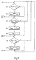
- ein Ablaufdiagramm eines erfindungsgemäßen Verfahrens zur Bestimmung eines momentan optimalen Druckes pKKB der Bremsen eines mit einem Zugfahrzeug verbundenen Anhängers,
- Fig. 2:
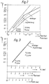
- den qualitativen Verlauf der Abbremsung z in Abhängigkeit der Drucke pALB und pKKB,
- Fig. 3:
- die graphische Darstellung einer Anpassung des Bremsverhaltens des Anhängers an das Bremsverhalten des Zugfahrzeuges,
- Fig. 4:
- eine graphische Darstellung der Zuordnung des Druckes pKKB zu dem Druck pL, der durch die Stellung sBWG des Bremswertgebers gegeben ist,
- Fig. 5:
- ein numerisch verbessertes Verfahren zur rechnerischen Bestimmung der graphischen Darstellung der Fig. 4,
- Fig. 6:
- ein Ablaufdiagramm betreffend die Regelung der Koppelkraft FKop und
- Fig. 7:
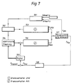
- ein System-Blockschaltbild der Steuerung und der Regelung im Zusammenspiel in Verbindung mit dem Zugfahrzeug und dem Anhänger.
- Fig. 1:
- 2 shows a flowchart of a method according to the invention for determining an instantaneously optimal pressure p KKB of the brakes of a trailer connected to a towing vehicle,
- Fig. 2:
- the qualitative course of the deceleration z as a function of the pressures p ALB and p KKB ,
- Fig. 3:
- the graphic representation of an adaptation of the braking behavior of the trailer to the braking behavior of the towing vehicle,
- Fig. 4:
- a graphical representation of the assignment of the pressure p KKB to the pressure p L , which is given by the position s BWG of the brake value transmitter,
- Fig. 5:
- 4 shows a numerically improved method for calculating the graphic representation of FIG. 4,
- Fig. 6:
- a flow chart regarding the control of the coupling force F Kop and
- Fig. 7:
- a system block diagram of the control and regulation in conjunction with the towing vehicle and the trailer.
Fig. 1 zeigt ein Ablaufdiagramm eines erfindungsgemäßen Verfahrens, bei dem zunächst in dem Schritt 101 geprüft wird, ob die Bedingung erfüllt ist, daß die gespeicherten Zuordnungen der Stellung des Bremswertgebers sBWG zu dem eingestellten Druck pKKB generell zurückgesetzt werden müssen, weil sich die Beladung und/oder Konstellation des aus einem Zugfahrzeug und einem Anhänger bestehenden Lastzuges möglicherweise geändert hat. In dem Ausführungsbeispiel nach Fig. 1 ist diese Prüfung dadurch realisiert, daß geprüft wird, ob der Motor aus ist. In diesem Fall erfolgt ein Übergang zu dem Schritt 102, in dem ein Reset aller gespeicherter Zuordnungen der Stellung des Bremswertgebers sBWG zu dem eingestellten Druck pKKB erfolgt. Es gelten dann wiederum die sich aus dem bisherigen Stand der Technik ergebenden Ausgangsabstimmungen zur Zuordnung eines Druckes pKKB zu der Stellung sBWG des Bremswertgebers. Diese vorläufige Zuordnung kann beispielsweise derart sein, daß zunächst der volle Druck pALB übergeben wird, so daß der Wert des Druckes pKKB gleich dem Wert des Druckes pALB wird. Wird dann bei einem Bremsvorgang ein stationärer Zustand erreicht, kann diese vorläufige Zuordnung weiter verbessert werden, indem das sich bei diesem Bremsvorgang ergebende Verhältnis zwischen dem Druck pALB und dem Druck pKKB bei den nächsten Bremsvorgängen verwendet wird, um einen Sollwert für den Druck pKKB zu bestimmen, bis das im folgenden beschriebene Verfahren zur Bestimmung eines Sollwertes für den Druck pKKB durchgeführt ist. Dabei kann diese vorläufige Zuordnung durch eine Mittelung über 10 Werte erfolgen.Fig. 1 shows a flow chart of a method according to the invention, in which it is first checked in
In dem Schritt 103 erfolgt dann eine Überprüfung, ob ein Bremsvorgang vorliegt. Diese Überprüfung wird dadurch realisiert, daß festgestellt wird, ob die Stellung sBWG des Bremswertgebers - im Ausführungsbeispiel der Fig. 1 ein Bremspedal - oberhalb eines vorgegebenen Schwellwertes sBWG,Schwelle liegt. In dem Ausführungsbeispiel nach Fig. 1 kann dieser Schwellwert in der Größenordnung von ca. 20% der vollen Betätigung des Bremspedals liegen. Wurde dabei festgestellt, daß ein Bremsvorgang vorliegt, wird in dem Schritt 104 ein der momentanen Stellung sBWG des Bremswertgebers zugeordneter Wert des Druckes pKKB als Sollwert vorgegeben.A check is then carried out in
Entsprechend dem Schritt 105 erfolgt zusätzlich zu dem anzusteuernden Sollwert, der entsprechend dem Schritt 104 bestimmt wurde, eine Regelung des Istwertes des Druckes pKKB auf einen solchen Wert, daß die Koppelkraft FKop zwischen dem Zugfahrzeug und dem Anhänger gleich dem für diese Koppelkraft FKop vorgegebenen Sollwert FKop,soll ist.According to step 105, in addition to the target value to be controlled, which was determined in accordance with
In dem Schritt 106 wird dann geprüft, ob der Bremsvorgang ausgeregelt ist, d.h. ob die Koppelkraft FKop für eine Zeitdauer oberhalb eines vorgegebenen Schwellwertes, der beispielsweise gleich 0,5 s sein kann, gleich dem Sollwert FKop,soll der Koppelkraft ist. Aufgrund von Schwankungen der Meßwerte durch Meßfehler und durch Störungen durch Fahrbahnunebenheiten kann es zu Ungenauigkeiten kommen, so daß Abweichungen der Koppelkraft FKop von dem Sollwert FKop,soll der Koppelkraft unterhalb eines Schwellwertes, der beispielsweise in der Größenordnung von 3 kN liegen kann, so gewertet werden, daß die Koppelkraft FKop gleich dem Sollwert FKop,soll der Koppelkraft ist. Ist dies der Fall, wird entsprechend dem Schritt 107 die Zuordnung der Stellung sBWG des Bremswertgebers zu dem ausgeregelten Druck pKKB für die Bestimmung eines Sollwertes des Druckes pKKB bei künftigen Bremsvorgängen herangezogen.In
Entsprechend der Darstellung der Fig. 1 ist es auch möglich, den dargestellten erfindungsgemäßen Ablauf in mehrere Teile zu unterteilen, wobei der Darstellung der Fig. 1 eine Unterteilung in drei Teile zu entnehmen ist. Dabei kann von einer zentralen Steuereinheit veranlaßt ein sich zyklisch wiederholender Ablauf jedes einzelnen der drei Teile realisiert werden, wobei dann auch unterschiedliche Zykluszeiten für die drei Teile möglich sind.According to the illustration in FIG. 1, it is also possible to divide the sequence according to the invention into several parts, the illustration in FIG. 1 showing a division into three parts. A central control unit can cause a cyclically repeating sequence of each of the three parts to be implemented, in which case different cycle times are also possible for the three parts.
So können beispielsweise die Schritte 101 und 102 zusammengefaßt werden, indem veranlaßt durch ein Eingangssignal 201 dieser erste Teil gestartet wird, wobei durch das Rückgabesignal 202 der Ablauf dieses ersten Teiles des erfindungsgemäßen Verfahrens wieder beendet wird. Außerdem können die Schritte 103, 104 und 105 zusammengefaßt werden, indem veranlaßt durch ein Eingangssignal 203 dieser zweite Teil gestartet wird, wobei durch das Rückgabesignal 204 der Ablauf dieses zweiten Teiles des erfindungsgemäßen Verfahrens wieder beendet wird. Es werden dann außerdem die Schritte 106 und 107 zusammengefaßt, indem veranlaßt durch ein Eingangssignal 205 dieser dritte Teil gestartet wird, wobei durch das Rückgabesignal 206 der Ablauf dieses dritten Teiles des erfindungsgemäßen Verfahrens wieder beendet wird.For example, steps 101 and 102 can be combined by starting this first part with an
Fig. 2 zeigt den qualitativen Verlauf der Abbremsung z in Einheiten der Erdbeschleunigung g für ein Zugfahrzeug sowie einen Anhänger in Abhängigkeit von dem jeweiligen Druck pALB und pKKB. Der das Zugfahrzeug betreffenden Kurve der Fig. 2 ist bei einem Druck pALB von 4 bar zu entnehmen, daß das ALB-Ventil bei diesem Wert des Druckes pALB auf eine größere Minderung umschaltet, was durch den entsprechenden Knick dieser Kurve sichtbar wird. Demnach können die jeweiligen Abbremsungen z für das Zugfahrzeug und den Anhänger in Form folgender Gleichungen angegeben werden:
Für das Zugfahrzeug:![]()
![]()

For the towing vehicle: ![]()
![]()
Grundsätzlich ist es also möglich, für jeden der beiden Bereiche pALB < 4 bar und pALB > 4 bar aus jeweils wenigstens zwei Meßpunkten die Geradengleichungen (4) und (5) durch Bestimmung der entsprechenden Steigung und des entsprechenden Achsenabschnittes zu bestimmen. Es ergibt sich somit eine Zuordnung des Druckes pALB zu dem Druck pKKB, die einem Bremsvorgang entspricht, bei dem die Koppelkraft FKop gleich 0 ist. Da andererseits die Zuordnung des Druckes pALB zu der Stellung des Bremswertgebers sBWG bekannt ist, läßt sich somit unmittelbar eine Zuordnung der Stellung des Bremswertgebers sBWG zu dem Druck pKKB angeben, bei der die Koppelkraft FKop gleich 0 wird. Es ist dann möglich, die Stellung des Bremswertgebers sBWG zu erfassen und entsprechend dieser Stellung entsprechend dem Schritt 104 einen anzusteuernden Wert des Druckes pKKB auszugeben, so daß ein sehr schneller Abbau der Koppelkraft FKop gewährleistet ist.In principle, it is therefore possible to determine the straight line equations (4) and (5) for each of the two areas p ALB <4 bar and p ALB > 4 bar from at least two measuring points by determining the corresponding slope and the corresponding axis section. This results in a Assignment of the pressure p ALB to the pressure p KKB , which corresponds to a braking process in which the coupling force F Kop is 0. On the other hand, since the assignment of the pressure p ALB to the position of the brake value transmitter s BWG is known, an assignment of the position of the brake value transmitter s BWG to the pressure p KKB can be specified at which the coupling force F Kop becomes 0. It is then possible to detect the position of the brake value transmitter s BWG and, in accordance with this position, to output a value of the pressure p KKB to be controlled in accordance with
Da die meisten Bremsvorgänge im Bereich kleiner Abbremsungen stattfinden, ist zu erwarten, daß sich nur relativ wenige Meßpunkte ergeben, mit denen eine Zuordnung der Stellung sBWG des Bremswertgebers zum Druck pKKB durchgeführt werden könnte, wenn der Druck pALB größer als 4 bar ist. In einer besonders vorteilhaften Ausführungsform des erfindungsgemäßen Verfahrens kann aus der Zuordnung der Stellung sBWG des Bremswertgebers zum Sollwert des Druckes pKKB für Werte des Druckes pALB < 4 bar auf die Zuordnung der Stellung sBWG des Bremswertgebers zum Sollwert des Druckes pKKB für Werte des Druckes pALB > 4 bar geschlossen werden.Since most braking processes take place in the area of small decelerations, it can be expected that there will be only relatively few measuring points with which the position s BWG of the braking value transmitter could be assigned to the pressure p KKB if the pressure p ALB is greater than 4 bar . In a particularly advantageous embodiment of the method according to the invention, the assignment of the position s BWG of the brake value transmitter to the setpoint value of the pressure p KKB for values of the pressure p ALB <4 bar can be used to assign the position s BWG of the brake value transmitter to the setpoint value of the pressure p KKB for values of the pressure p ALB > 4 bar.
Es kann dazu beispielsweise eine Hilfsgröße des Druckes mit der Bezeichnung pL eingeführt werden, die im Bereich 0 <= pALB <= 4 bar gleich dem Druck pALB ist. Für Werte des Druckes pALB größer als 4 bar ergibt sich dann eine Umrechnung der Werte des Druckes pALB in zugehörige Werte des Druckes pL derart, daß mittels der Gl. (1) eine Zuordnung der Abbremsung des Zugfahrzeuges zLKW über dem Druck pL statt über dem Druck pALB getroffen wird. Diese Zuordnung gilt dann für den gesamten Bereich des Druckes. Die Änderung der Zuordnung gemäß den anderen Parametern der Gl. (2) für Werte des Druckes pALB größer als 4 bar wird dann durch die Umrechnung berücksichtigt. Gemäß dieser Anforderung ergibt sich somit folgende Umrechnung für den Druck pALB in den Druck pL:
Da nun die Zuordnung der Stellung des Bremswertgebers sBWG zu dem Druck pALB bekannt ist, kann durch eine Umstellung der Gl. (6) und (7) auch unmittelbar eine Zuordnung der Stellung des Bremswertgebers sBWG zu dem Druck pL angegeben werden. Werden nun bei stationären Bremsvorgängen (Koppelkraft gleich dem Sollwert) die Zuordnungen der Drucke pKKB zu den Drucken pL abgespeichert, kann aus diesen Zuordnungen entsprechend der beispielhaften Darstellung in Fig. 4 unmittelbar eine Geradengleichung für den Druck pKKB in Abhängigkeit des Druckes pL angegeben werden. Somit ist es möglich, unter Verwendung dieser Geradengleichung und der Zuordnung des Druckes pL zu der Stellung des Bremswertgebers sBWG eine Zuordnung der Stellung des Bremswertgebers sBWG zu dem Druck pKKB anzugeben.Since the assignment of the position of the brake value transmitter s BWG to the pressure p ALB is now known, a change in Eq. (6) and (7) an assignment of the position of the brake value transmitter s BWG to the pressure p L can also be given directly. If the assignments of the pressures p KKB to the pressures p L are now stored in the case of stationary braking processes (coupling force equal to the target value), a straight line equation for the pressure p KKB as a function of the pressure p L can be derived from these assignments in accordance with the exemplary illustration in FIG. 4 can be specified. Thus it is possible, using this linear equation and the assignment of the pressure p L to the position of the braking value sensor s BWG an assignment of the position s BWG of the braking value sensor to the pressure p KKB indicated.
Weiterhin sind den Fig. 4 und 5 einige vorteilhafte Aspekte bzgl. der Vorgehensweise der Bestimmung einer Geradengleichung des Druckes pKKB über dem Druck pL zu entnehmen. Um eine "hinreichende" lineare Unabhängigkeit der der Berechnung der Geradengleichung zugrundeliegenden Meßpunkte zur Vermeidung numerischer Schwierigkeiten zu gewährleisten, ist es vorteilhaft, die Berechnung der Geradengleichung entsprechend dem Schritt 503 erst dann durchzuführen, wenn wenigstens zwei Meßpunkte vorliegen, deren Werte des Druckes pL wenigstens 1 bar Differenz aufweisen. In dem Ablaufdiagramm der Fig. 5 entspricht dies dem Schritt 501. Ansonsten kann es bei der Bestimmung der Geradengleichung aufgrund von Schwankungen der Meßwerte zu numerischen Schwierigkeiten kommen. Aus demselben Grund kann in einer besonders vorteilhaften Ausführungsform des erfindungsgemäßen Verfahrens der Bereich der insgesamt auftretenden Drucke pL entsprechend dem Schritt 502 und der Darstellung der Fig. 4 in mehrere Bereiche unterteilt werden. Es wird dann zunächst für jeden dieser Bereiche eine Mittelung aller in den jeweiligen Bereichen auftretenden Meßwerte vorgenommen. Aus den gemittelten Werten dieser einzelnen Bereiche wird dann die Geradengleichung bestimmt. Es hat sich dabei als vorteilhaft erwiesen, den Bereich der auftretenden Drucke pL in 6 Bereiche zu unterteilen.Furthermore, FIGS. 4 and 5 show some advantageous aspects with regard to the procedure for determining a straight line equation of the pressure p KKB over the pressure p L. To avoid "sufficient" linear independence of the measuring points on which the calculation of the straight line equation is based To ensure numerical difficulties, it is advantageous to carry out the calculation of the straight line equation in accordance with
Außerdem können neuere Meßwerte bei der Mittelung eine größere Gewichtung erfahren als frühere Meßwerte. Beispielsweise kann die Mittelung der früheren Meßwerte insgesamt mit 1 gewichtet werden und der aktuelle Meßwert gegenüber der Mittelung der früheren Meßwerte mit 0,25.In addition, newer averaging measurements can be weighted more heavily than previous measurements. For example, the averaging of the previous measured values can be weighted overall by 1 and the current measured value compared to the averaging of the previous measured values by 0.25.
Das bisher beschriebene Verfahren stellt lediglich ein Ausführungsbeispiel dar, wie eine Zuordnung der Stellung sBWG des Bremswertgebers zu dem Sollwert des Druckes pKKB erfolgen kann. Wesentlich an der Erfindung ist, daß die bei früheren stationären Bremsvorgängen ermittelten Zuordnungen bei künftigen Bremsvorgängen zur Bestimmung eines entsprechend Schritt 104 anzusteuernden Wertes des Druckes pKKB herangezogen werden.The method described so far represents only one exemplary embodiment of how the position s BWG of the brake value transmitter can be assigned to the setpoint value of the pressure p KKB . It is essential to the invention that the assignments determined in previous stationary braking processes are used in future braking processes to determine a value of the pressure p KKB to be controlled in accordance with
So ist es beispielsweise auch möglich, mittels der Gl. (4) zunächst die Größen µAnh und βAnh zu bestimmen, wobei diese Bestimmung beispielsweise mittels der Methode der Parameteridentifikation anhand von mehreren Meßpunkten erfolgen kann. Mit den auf diese Art und Weise bestimmten Größen µAnh und βAnh kann dann auch für Werte des Druckes pALB > 4 bar die Gl. (5) gelöst werden.For example, it is also possible to use Eq. (4) first determine the quantities µ Anh and β Anh , this determination being able to be carried out, for example, by means of the method of parameter identification on the basis of several measuring points. With the variables µ Anh and β Anh determined in this way, the equation can also be used for values of pressure p ALB > 4 bar. (5) can be solved.
Fig. 6 ist ein Verfahrensablauf der Regelung der Koppelkraft FKop zu entnehmen. Als Ausgangsgröße dieser Regelung ergibt sich ein Wert des Druckes pKKB, der zu dem entsprechend Schritt 104 (Fig. 1) anzusteuernden Wert des Druckes pKKB addiert wird. Ziel dieser Regelung ist es, eventuell noch bestehende Koppelkräfte FKop durch diese Regelung auf ihren Sollwert FKop,soll zu bringen. Da nun aber im normalen Fahrbetrieb Situationen auftreten können, in denen Koppelkräfte auftreten, die nicht ausgeregelt werden sollen, müssen vor dem Einsatz dieser Regelung zunächst einige Kriterien überprüft werden.6 shows a process sequence for regulating the coupling force F Kop . The output variable of this regulation results in a value of the pressure p KKB , which is added to the value of the pressure p KKB to be controlled in accordance with step 104 (FIG. 1). The aim of this regulation is to bring coupling forces F Kop , which may still be present, to their desired value F Kop, should by means of this regulation. However, since situations can occur in normal driving operation in which coupling forces occur that should not be corrected, some criteria must first be checked before using this control.
So darf diese Regelung beispielsweise bei Rückwärtsfahrt nicht in Aktion treten, da bei der Rückwartsfahrt in der dann gültigen Fahrtrichtung gesehen der Anhänger vor dem Zugfahrzeug herfährt. Bremst bei einer Rückwärtsfahrt beispielsweise der Anhänger schwächer als das Zugfahrzeug, tritt eine Koppelkraft FKop > 0 auf. Eine solche Koppelkraft FKop wird bei normaler Vorwärtsfahrt dadurch ausgeregelt, daß die Bremskraft (der Bremsdruck) des Anhängers abgeregelt wird. Im Falle der Rückwärtsfahrt würde durch eine solche Maßnahme aber die Koppelkraft FKop gerade weiter erhöht. Dies wäre zu umgehen, wenn man das Vorzeichen des Istwertes der Koppelkraft bei der Regelung ändert. Andererseits kann in einer vorteilhaften Ausführungsform die Regelung bei der Rückwärtsfahrt ausgeblendet werden, da Rückwärtsfahrten im allgemeinen nur langsam durchgeführt werden und infolge dessen auch keine kritischen Fahrzustände selbst beim Auftreten von Koppelkräften auftreten können. Deswegen wird in dem Schritt 601 anhand der Fahrzeuggeschwindigkeit vF die Bedingung überprüft, ob eine Rückwärtsfahrt vorliegt. Ist dies der Fall, erfolgt keine Regelung der Koppelkraft. Andernfalls erfolgt ein Übergang zu dem Schritt 602, in dem eine weitere Prüfung stattfindet.For example, this regulation must not come into action when driving backwards, since the trailer drives in front of the towing vehicle when viewed in the direction of travel that is then valid. If, for example, the trailer brakes less than the towing vehicle when reversing, a coupling force F Kop > 0 occurs. Such a coupling force F Kop is corrected during normal forward travel in that the braking force (braking pressure) of the trailer is reduced. In the case of backward travel, the coupling force F Kop would just be further increased by such a measure. This could be avoided if you change the sign of the actual value of the coupling force in the control. On the other hand, in an advantageous embodiment, the regulation can be masked out when reversing, since reversing is generally carried out only slowly and consequently also no critical driving conditions can occur even when coupling forces occur. For this reason, the condition is checked in
In dem Schritt 602 wird überprüft, ob der aus dem Zugfahrzeug und dem Anhänger bestehende Lastzug stillsteht. Beispielsweise können beim Anhalten am Berg zwischen Zugfahrzeug und Anhänger Verspannungen auftreten, die zu bleibenden Koppelkräften führen, so lange der Lastzug steht, wobei diese Koppelkräfte dann unabhängig von dem den Bremsdruck des Anhängers repräsentierenden Druck pKKB sind. Deshalb wird gemäß dem Schritt 602 überprüft, ob der Lastzug steht, d.h. ob die Fahrzeuggeschwindigkeit vF gleich 0 ist, wobei bei stehendem Lastzug die Koppelkraftregelung ausgeschaltet wird.In
Weiterhin kann eine negative Koppelkraftspitze beim Beginn eines Bremsvorganges auftreten. Da dann durch die Regelung eine verhältnismäßig große Stellgröße ausgegeben wird, die in der Folge dann im allgemeinen zu einem Überschwingen führt, ist es vorteilhaft, die Regelung zu Beginn eines Bremsvorganges auszublenden. Deshalb wird in dem Schritt 603 überprüft, ob seit Beginn des Bremsvorganges die Zeitdauer tBrems vergangen ist. Diese Zeitdauer tBrems hängt dabei wesentlich von dem Ansprechverhalten der Bremsen des Anhängers im Verhältnis zu den Bremsen des Zugfahrzeuges ab und kann in der Größenordnung von ca. 1 s liegen. Diese Koppelkraftspitze zu Beginn eines Bremsvorganges kann auch vorteilhaft dadurch minimiert werden, daß zu Beginn eines Bremsvorganges ein Druckinshot durchgeführt wird, indem beispielsweise ein Wert des Druckes pKKB von ca. 3 bar für eine Zeitdauer von ca. 0,5 s angelegt wird.Furthermore, a negative coupling force peak can occur at the start of a braking process. Since the control then outputs a relatively large manipulated variable, which then generally leads to overshoot, it is advantageous to hide the control at the beginning of a braking operation. It is therefore checked in
Aufgrund von Ventilhysteresen und Schwankungen in der Reibung der Radbremsen ist es weiterhin vorteilhaft, die Regelung erst bei einem Druck oberhalb eines Wertes von beispielsweise pKKB > 0,5 bar zu aktivieren, da es sonst zu Instabilitäten in der Regelung kommen kann. Bei niedrigen Bremsdrücken kommt es nur zu geringen Verzögerungen, so daß der Bremsvorgang insgesamt nicht instabil werden kann. Deswegen wird in dem Schritt 604 überprüft, ob der Druck pKKB einen bestimmten Schwellwert pKKB,Schwelle überschritten hat.Due to valve hysteresis and fluctuations in the friction of the wheel brakes, it is further advantageous to activate the control only at a pressure above a value of, for example, p KKB > 0.5 bar, since otherwise the control may become unstable. At low brake pressures, there are only slight delays so that the braking process as a whole cannot become unstable. It is therefore checked in
Außerdem wird in dem Schritt 605 geprüft, ob der Lastzugführer eine Dauerbremsanlage wie z.B. eine Motorbremse oder einen Retarder eingeschaltet hat. In diesem Fall kommt es zu Koppelkräften, die nicht ausgeregelt werden sollen. Bei einer Bergabfahrt könnten sich die Bremsen des Anhängers überhitzen, wenn das Zugfahrzeug mittels der Motorbremse abgebremst wird. Im Falle, daß die Dauerbremsanlage allein betätigt wird, erfolgt somit keine Regelung der Koppelkraft FKop.In addition, it is checked in
In dem Schritt 606 wird überprüft, ob zusätzlich zur Dauerbremsanlage noch die Betriebsbremsanlage des Lastzuges betätigt wird. In diesem Fall kann entsprechend der Darstellung in dem Schritt 607 als Sollwert FKop,soll der Koppelkraft eine Größe berechnet werden, die die Betätigung der Dauerbremsanlage berücksichtigt. Allgemein ergibt sich die Koppelkraft FKop nach folgender Gleichung:
Darin bedeuten:
- mAnh :
- Masse des Anhängers und
- mLKW :
- Masse des Zugfahrzeuges.
Where:
- m appendix :
- Mass of the trailer and
- m truck :
- Mass of the towing vehicle.
Entsprechend der Darstellung in dem Schritt 608 erfolgt dann eine Regelung des Druckes pKKB auf einen solchen Wert, daß die Koppelkraft FKop ihren Sollwert FKop,soll erreicht. Diese Regelung kann dabei beispielsweise mittels eines PID-Reglers erfolgen, wobei sich zeigte, daß ein stabiles Regelverhalten erreicht wurde bei einer Abtastzeit des Reglers von ca. 50 ms und Reglerparametern, die folgende Größenordnungen annehmen können:
Entsprechend der Darstellung der Fig. 7 ergibt sich nun ein Funktionsblockschaltbild des erfindungsgemäßen Verfahrens. Dabei wirkt auf den Lastzugführer entsprechend dem Block 701 der spürbare Istwert der Verzögerung z ein sowie ein sich aus der allgemeinen Fahrsituation ergebender Sollwert für die Verzögerung z. Der Fahrer wirkt in diesem Fall als Regler, der in Abhängigkeit von der Regeldifferenz entsprechend dem Block 702 das Bremspedal betätigt. Die Betätigung des Bremspedals führt entsprechend dem Block 703 unmittelbar unter Berücksichtigung des Bremsverhaltens des LKW zu einer Verzögerung zLKW des LKW. Weiterhin wird durch die Betätigung des Bremspedals die elektronische Steuerung 704 aktiviert, die einen anzusteuernden Sollwert für den Druck pKKB in Abhängigkeit der Betätigung des Bremspedals ausgibt. Zu diesem Sollwert wird zusätzlich ein Ausgangswert des Reglers 705 addiert. Dieser sich so ergebende Wert des Bresmdruckes pKKB führt dann entsprechend dem Block 706 zu einer Verzögerung zAnh des Anhängers. Außerdem wird die elektronische Steuerung 704 von dem Regler 705 unmittelbar beeinflußt, wenn ein stationärer Bremsvorgang vorliegt, indem die Zuordnung der Stellung des Bremspedals zu dem momentanen Wert des Druckes pKKB bei künftigen Bestimmungen eines anzusteuernden Sollwertes berücksichtigt wird. Entsprechend dem Block 707 kommt es zu einer Gesamtverzögerung z des Lastzuges, die der Fahrer als Istwert wahrnimmt. Außerdem treten bei unterschiedlichen Verzögerungen des Zugfahrzeuges und des Anhängers Koppelkräfte auf, die von dem Sensor 708 erfaßt werden und von einem Sollwert FKop,soll subtrahiert werden, um dann dem Regler 705 als Eingangsgröße zugeführt zu werden.7, a functional block diagram of the method according to the invention is now obtained. The noticeable actual value of the deceleration z acts on the truck driver in accordance with
Claims (13)
- Method of determining an instantaneously optimum pressure of the brakes of a trailer or semitrailer connected to a tractor for the purpose of adjusting the coupling force occurring betwen the tractor and the trailer or semitrailer to the conditions instantaneously present, characterised- in that during at least one braking process in which the coupling force FKop has been set (106) to a pre-determined desired value FKop,desired, the assignment of the braking pressure pALB, present upstream of the automatically load-dependent braking force valve, of the brakes of the tractor with a pressure pKKB at the coupling head brake between the tractor and the trailer or semitrailer is determined,- in that from assignments pf pALB to pKKB determined in the region of values of the pressure pALB below the operating pressure of the automatically load-dependent braking force valve, on the basis of a first approximation line for the deceleration z of the tractor over pressures values pALB below the operating pressure of the automatically load-dependent braking force valve having a parameter µ1,LKW for the line gradient and a parameter β1,LKW for the zero-point offset and of a second approximation line for the deceleration z of the tractor over pressure values pALB above the operating pressure of the automatically load-dependent braking force valve having a parameter µ2,LKW for the line gradient and a parameter β2,LKW for the zero-point offset a conclusion is drawn regarding assignments of pALB to PKKB in the region of values of the pressure pALB above the operating pressure of the automatically load-dependent braking force valve, as they are necessary or occur in instances of strong braking, and- in that during subsequent braking processes (103) the target value of the pressure pKKB of the brakes of the trailer or semitrailer is determined from the assignment of the pressure pALB of the brakes of the tractor to the pressure pKKB (107).
- Method according to Claim 1, characterised in that there is added to the target value of the pressure pKKB (704) an output variable of the regulation (705) such that the coupling force FKop becomes equal to its desired value FKop,desired.
- Method according to claim 2, characterised in that no regulation of the coupling force FKop is performed when at least one of the conditions is fulfilled:- the vehicle is driving backwards (601),- the road train consisting of the tractor and the trailer is stationary (602),- from the start of the braking process only a time interval has elapsed such that the peak coupling force arising at the start of a braking process is still present (603), and- the braking process (604) is a weak one.
- Method according to Claim 2 or 3, characterised in that no regulation of the coupling force is performed if a retarding unit is in operation (605).
- Method according to Claim 2 or 3, characterised in that in the event of simultaneous operation of a retarding unit and the service brake system (605, 606) only the coupling force FKop arising owing to the actuation of the service brake system is stabilised (607).
- Method according to one of Claims 2 to 5, characterised in that the controller has a PID action.
- Method according to one of Claims 1 to 6, characterised in that the pressure pALB is directly assigned to the pressure pKKB.
- Method according to one of Claims 1 to 6, characterised in that the position sBWG, determining the magnitude of the pressure pALB, of the braking value sensor is assigned to the pressure pKKB.
- Method according to one of Claims 1 to 8, characterised in that- the pressure pALB is converted into a value of the pressure pL in such a way that a continuous straight line results when the retardation zLKW is plotted against the pressure pL,- in order to determine a target value of the pressure pKKB the straight line equation between the pressure pKKB and the pressure pL is determined from at least two measuring points, and- the assignment of the position sBWG of the braking value sensor to the pressure pKKB is determined (107) using the assignment between the pressure pL and the position sBWG of the braking value sensor,when the coupling force FKop is equal to its desired value FKop,desired (106).
- Method according to Claim 9, characterised in that the minimum distance between at least two measuring points for the value of the pressure pL is greater than 1 bar (501).
- Method according to Claim 10, characterised in that- the measured values are firstly subdivided into individual ranges with regard to the pressure pL,- an averaging of the measured values in the individual ranges is performed (502), and- a determination of the parameters of the straight line equation is undertaken (503) by means of the values averaged in the individual ranges.
- Method according to one of Claims 1 to 11, characterised in that a reset of the assignments of the values of the pressure pKKB to the values of the pressure pALB or to the positions sBWG of the braking value sensor is performed when the road train is stationary for longer than a specific duration.
- Method according to one of Claims 1 to 11, characterised in that a reset of the assignments of the values of the pressure pKKB to the values of the pressure pALB or to the positions sBWG of the braking value sensor is performed when the engine of the road train is switched off.
Applications Claiming Priority (2)
| Application Number | Priority Date | Filing Date | Title |
|---|---|---|---|
| DE4035805 | 1990-11-10 | ||
| DE4035805A DE4035805C1 (en) | 1990-11-10 | 1990-11-10 |
Publications (2)
| Publication Number | Publication Date |
|---|---|
| EP0485738A1 EP0485738A1 (en) | 1992-05-20 |
| EP0485738B1 true EP0485738B1 (en) | 1995-10-18 |
Family
ID=6418007
Family Applications (1)
| Application Number | Title | Priority Date | Filing Date |
|---|---|---|---|
| EP91117191A Expired - Lifetime EP0485738B1 (en) | 1990-11-10 | 1991-10-09 | Method for determining the instantaneous optimal brake pressure of a trailer or semi-trailer, attached to a tractor |
Country Status (4)
| Country | Link |
|---|---|
| US (1) | US5281006A (en) |
| EP (1) | EP0485738B1 (en) |
| DE (1) | DE4035805C1 (en) |
| ES (1) | ES2080213T3 (en) |
Families Citing this family (19)
| Publication number | Priority date | Publication date | Assignee | Title |
|---|---|---|---|---|
| DE4136571C1 (en) * | 1991-11-07 | 1993-03-18 | Mercedes-Benz Aktiengesellschaft, 7000 Stuttgart, De | |
| DE4243245A1 (en) * | 1992-12-19 | 1994-06-23 | Wabco Westinghouse Fahrzeug | Method for braking a vehicle train |
| US5438516A (en) * | 1993-10-29 | 1995-08-01 | Williams Controls, Inc. | Integrated vehicle brake control device position sensor with precalibrated multiple sensor outputs |
| DE4412430C1 (en) * | 1994-04-11 | 1995-08-10 | Knorr Bremse Systeme | Adjustment of distribution of brake force between tractor and trailer |
| DE4431698C1 (en) * | 1994-09-06 | 1995-09-21 | Daimler Benz Ag | Angle limiting device for 2-part omnibus |
| DE4446358C1 (en) * | 1994-12-23 | 1995-12-07 | Knorr Bremse Systeme | rake force distribution regulation system for tractor/trailer vehicle |
| DE19510933A1 (en) * | 1995-03-24 | 1996-09-26 | Wabco Gmbh | Method for determining the response pressure of a pressure-actuated brake in a vehicle brake system |
| DE19510934A1 (en) * | 1995-03-24 | 1996-09-26 | Wabco Gmbh | Method for braking a vehicle |
| DE19519768C2 (en) * | 1995-05-30 | 1997-05-28 | Knorr Bremse Systeme | Method and device for adjusting the braking force of a trailer of a vehicle group consisting of a towing vehicle and at least one trailer |
| US6012781A (en) * | 1995-07-14 | 2000-01-11 | Knorr-Bremse Systeme Fur Nutzfahrzeuge Gmbh | Brake control arrangement for composite vehicles |
| DE19633834B4 (en) | 1996-08-22 | 2011-10-06 | Robert Bosch Gmbh | Method and device for controlling the brake system of a vehicle |
| GB9703356D0 (en) * | 1997-02-18 | 1997-04-09 | Lucas Ind Plc | Trailer brake control |
| ATE292033T1 (en) * | 2002-09-18 | 2005-04-15 | Zbinden Posieux Sa | METHOD FOR CONTROLLING A BRAKE DEVICE OF A TRAILER AND BRAKE DEVICE FOR IMPLEMENTING THIS METHOD |
| DE10261547A1 (en) * | 2002-12-23 | 2004-07-08 | Wabco Gmbh & Co. Ohg | Procedure for applying energy to a combination of vehicles |
| DE10315662A1 (en) * | 2003-04-04 | 2004-10-14 | Lucas Automotive Gmbh | Method for operating a vehicle unit and electronic system for a motor vehicle |
| DE102009031851B4 (en) * | 2009-07-03 | 2021-02-11 | Dipl. Ing. Tietjen Gmbh | Method for braking a tractor-trailer combination and device |
| ITMO20120320A1 (en) * | 2012-12-21 | 2014-06-21 | Cnh Italia Spa | METHOD AND APPARATUS FOR CHECKING THE BRAKING OF A TRAILER TRAILER COMBINATION. |
| DE102020106448A1 (en) * | 2020-03-10 | 2021-09-16 | Wabco Europe Bvba | Method for brake control of a vehicle combination |
| DE102021115400A1 (en) | 2021-06-15 | 2022-12-15 | Zf Cv Systems Global Gmbh | Method and device for brake control of a vehicle train |
Family Cites Families (10)
| Publication number | Priority date | Publication date | Assignee | Title |
|---|---|---|---|---|
| US3955652A (en) * | 1969-05-23 | 1976-05-11 | Ab Linde International | Operating systems for trailer brakes |
| DE2164325C3 (en) * | 1971-12-23 | 1975-10-09 | Daimler-Benz Ag, 7000 Stuttgart | Device for regulating the braking force on the wheels of motor vehicle trailers |
| DE2820921A1 (en) * | 1978-05-12 | 1979-11-15 | Knorr Bremse Gmbh | BRAKE DEVICE FOR VEHICLES |
| US4763958A (en) * | 1984-10-17 | 1988-08-16 | Vbg Produkter Ab | Apparatus for matching the brake pressure of vehicle combinations to the actual load |
| GB8513686D0 (en) * | 1985-05-30 | 1985-07-03 | Lucas Ind Plc | Vehicle braking system |
| US4984852A (en) * | 1987-04-27 | 1991-01-15 | Eaton Corporation | Trailer mounted tractor-trailer brake control system |
| SE462152B (en) * | 1988-09-09 | 1990-05-14 | Saab Scania Ab | SETTING AND ARRANGEMENTS FOR BRAKE ADJUSTMENT BETWEEN A TRUCK VEHICLE AND A CONNECTED SEMITRAILER |
| DE3920096A1 (en) * | 1988-10-08 | 1990-04-12 | Bosch Gmbh Robert | AIR BRAKE DEVICE |
| GB8827101D0 (en) * | 1988-11-19 | 1988-12-21 | Lucas Ind Plc | Trailer brake control for towing vehicles having electronic brake control |
| DE3901270A1 (en) * | 1989-01-18 | 1990-07-19 | Bosch Gmbh Robert | AIR BRAKE DEVICE FOR MOTOR VEHICLES |
-
1990
- 1990-11-10 DE DE4035805A patent/DE4035805C1/de not_active Expired - Lifetime
-
1991
- 1991-10-09 ES ES91117191T patent/ES2080213T3/en not_active Expired - Lifetime
- 1991-10-09 EP EP91117191A patent/EP0485738B1/en not_active Expired - Lifetime
- 1991-11-08 US US07/789,844 patent/US5281006A/en not_active Expired - Fee Related
Also Published As
| Publication number | Publication date |
|---|---|
| DE4035805C1 (en) | 1992-03-05 |
| US5281006A (en) | 1994-01-25 |
| EP0485738A1 (en) | 1992-05-20 |
| ES2080213T3 (en) | 1996-02-01 |
Similar Documents
| Publication | Publication Date | Title |
|---|---|---|
| EP0485738B1 (en) | Method for determining the instantaneous optimal brake pressure of a trailer or semi-trailer, attached to a tractor | |
| DE4338066C1 (en) | Method for performing an automatic braking process for motor vehicles with an anti-lock braking system | |
| DE19744066B4 (en) | Method and device for detecting trailer operation in a motor vehicle | |
| DE19854184B4 (en) | Brake control device | |
| DE19724092B4 (en) | Method and device for determining the vehicle mass | |
| EP0697314B1 (en) | Method for load dependant brake pressure control of a tractor-trailer combination | |
| EP0173954B1 (en) | Brake pressure regulation process | |
| DE4430461A1 (en) | Method for controlling the brake pressure as a function of the pedal actuation speed | |
| DE4136571C1 (en) | ||
| DE19726116B4 (en) | Method for decelerating a vehicle | |
| EP0733532B1 (en) | Method for determining set pressure of a pressure-actuated brake in a vehicle brake system | |
| DE19859953A1 (en) | Device and method for stabilizing a vehicle combination consisting of a towing vehicle and a trailer or semitrailer | |
| DE19648936B4 (en) | Method and device for controlling the brake system of a vehicle | |
| DE102015012378A1 (en) | Method for adjusting brake pressures of a motor vehicle, brake system for carrying out the method and motor vehicle | |
| DE19633224A1 (en) | Air-brake system e.g. for tractor-trailer combination vehicle | |
| DE3512716C2 (en) | ||
| EP0733531B1 (en) | Method for braking a vehicle | |
| DE10335899A1 (en) | Device for longitudinal guidance of a motor vehicle by engagement in the brake system | |
| DE19739825B4 (en) | Method and device for controlling the brake system of a vehicle | |
| DE19633834B4 (en) | Method and device for controlling the brake system of a vehicle | |
| DE19625989A1 (en) | Method for operating a brake system, in particular an externally powered brake system of commercial vehicles | |
| DE19633835A1 (en) | Brake system for commercial vehicle and trailer | |
| EP0602353B1 (en) | Brake installation with at least one brake | |
| DE19981604B4 (en) | Method for operating a brake assist system | |
| EP0663327A2 (en) | Method to reduce the jerk of an automotive vehicle during braking to a complete standstill |
Legal Events
| Date | Code | Title | Description |
|---|---|---|---|
| PUAI | Public reference made under article 153(3) epc to a published international application that has entered the european phase |
Free format text: ORIGINAL CODE: 0009012 |
|
| AK | Designated contracting states |
Kind code of ref document: A1 Designated state(s): ES FR GB IT NL SE |
|
| 17P | Request for examination filed |
Effective date: 19920820 |
|
| 17Q | First examination report despatched |
Effective date: 19940211 |
|
| GRAA | (expected) grant |
Free format text: ORIGINAL CODE: 0009210 |
|
| ITF | It: translation for a ep patent filed |
Owner name: BARZANO' E ZANARDO ROMA S.P.A. |
|
| AK | Designated contracting states |
Kind code of ref document: B1 Designated state(s): ES FR GB IT NL SE |
|
| GBT | Gb: translation of ep patent filed (gb section 77(6)(a)/1977) |
Effective date: 19951216 |
|
| ET | Fr: translation filed | ||
| REG | Reference to a national code |
Ref country code: ES Ref legal event code: FG2A Ref document number: 2080213 Country of ref document: ES Kind code of ref document: T3 |
|
| PLBE | No opposition filed within time limit |
Free format text: ORIGINAL CODE: 0009261 |
|
| STAA | Information on the status of an ep patent application or granted ep patent |
Free format text: STATUS: NO OPPOSITION FILED WITHIN TIME LIMIT |
|
| 26N | No opposition filed | ||
| NLS | Nl: assignments of ep-patents |
Owner name: DAIMLER-BENZ AKTIENGESELLSCHAFT |
|
| REG | Reference to a national code |
Ref country code: GB Ref legal event code: 732E |
|
| REG | Reference to a national code |
Ref country code: FR Ref legal event code: TP |
|
| NLS | Nl: assignments of ep-patents |
Owner name: DAIMLERCHRYSLER AG |
|
| REG | Reference to a national code |
Ref country code: GB Ref legal event code: 732E |
|
| PGFP | Annual fee paid to national office [announced via postgrant information from national office to epo] |
Ref country code: GB Payment date: 20010914 Year of fee payment: 11 |
|
| PGFP | Annual fee paid to national office [announced via postgrant information from national office to epo] |
Ref country code: NL Payment date: 20010925 Year of fee payment: 11 |
|
| PGFP | Annual fee paid to national office [announced via postgrant information from national office to epo] |
Ref country code: SE Payment date: 20011001 Year of fee payment: 11 |
|
| PGFP | Annual fee paid to national office [announced via postgrant information from national office to epo] |
Ref country code: FR Payment date: 20011011 Year of fee payment: 11 |
|
| PGFP | Annual fee paid to national office [announced via postgrant information from national office to epo] |
Ref country code: ES Payment date: 20011024 Year of fee payment: 11 |
|
| REG | Reference to a national code |
Ref country code: GB Ref legal event code: IF02 |
|
| PG25 | Lapsed in a contracting state [announced via postgrant information from national office to epo] |
Ref country code: GB Free format text: LAPSE BECAUSE OF NON-PAYMENT OF DUE FEES Effective date: 20021009 |
|
| PG25 | Lapsed in a contracting state [announced via postgrant information from national office to epo] |
Ref country code: SE Free format text: LAPSE BECAUSE OF NON-PAYMENT OF DUE FEES Effective date: 20021010 Ref country code: ES Free format text: LAPSE BECAUSE OF NON-PAYMENT OF DUE FEES Effective date: 20021010 |
|
| PG25 | Lapsed in a contracting state [announced via postgrant information from national office to epo] |
Ref country code: NL Free format text: LAPSE BECAUSE OF NON-PAYMENT OF DUE FEES Effective date: 20030501 |
|
| GBPC | Gb: european patent ceased through non-payment of renewal fee |
Effective date: 20021009 |
|
| EUG | Se: european patent has lapsed | ||
| PG25 | Lapsed in a contracting state [announced via postgrant information from national office to epo] |
Ref country code: FR Free format text: LAPSE BECAUSE OF NON-PAYMENT OF DUE FEES Effective date: 20030630 |
|
| NLV4 | Nl: lapsed or anulled due to non-payment of the annual fee |
Effective date: 20030501 |
|
| REG | Reference to a national code |
Ref country code: FR Ref legal event code: ST |
|
| REG | Reference to a national code |
Ref country code: ES Ref legal event code: FD2A Effective date: 20031112 |
|
| PG25 | Lapsed in a contracting state [announced via postgrant information from national office to epo] |
Ref country code: IT Free format text: LAPSE BECAUSE OF NON-PAYMENT OF DUE FEES;WARNING: LAPSES OF ITALIAN PATENTS WITH EFFECTIVE DATE BEFORE 2007 MAY HAVE OCCURRED AT ANY TIME BEFORE 2007. THE CORRECT EFFECTIVE DATE MAY BE DIFFERENT FROM THE ONE RECORDED. Effective date: 20051009 |