EP0485672A1 - Knock down bulk container - Google Patents
Knock down bulk container Download PDFInfo
- Publication number
- EP0485672A1 EP0485672A1 EP90312487A EP90312487A EP0485672A1 EP 0485672 A1 EP0485672 A1 EP 0485672A1 EP 90312487 A EP90312487 A EP 90312487A EP 90312487 A EP90312487 A EP 90312487A EP 0485672 A1 EP0485672 A1 EP 0485672A1
- Authority
- EP
- European Patent Office
- Prior art keywords
- panels
- base
- container
- pair
- pockets
- Prior art date
- Legal status (The legal status is an assumption and is not a legal conclusion. Google has not performed a legal analysis and makes no representation as to the accuracy of the status listed.)
- Withdrawn
Links
Images


Classifications
-
- B—PERFORMING OPERATIONS; TRANSPORTING
- B65—CONVEYING; PACKING; STORING; HANDLING THIN OR FILAMENTARY MATERIAL
- B65D—CONTAINERS FOR STORAGE OR TRANSPORT OF ARTICLES OR MATERIALS, e.g. BAGS, BARRELS, BOTTLES, BOXES, CANS, CARTONS, CRATES, DRUMS, JARS, TANKS, HOPPERS, FORWARDING CONTAINERS; ACCESSORIES, CLOSURES, OR FITTINGS THEREFOR; PACKAGING ELEMENTS; PACKAGES
- B65D11/00—Containers having bodies formed by interconnecting or uniting two or more rigid, or substantially rigid, components made wholly or mainly of plastics material
- B65D11/18—Containers having bodies formed by interconnecting or uniting two or more rigid, or substantially rigid, components made wholly or mainly of plastics material collapsible, i.e. with walls hinged together or detachably connected
- B65D11/1833—Containers having bodies formed by interconnecting or uniting two or more rigid, or substantially rigid, components made wholly or mainly of plastics material collapsible, i.e. with walls hinged together or detachably connected whereby all side walls are hingedly connected to the base panel
-
- B—PERFORMING OPERATIONS; TRANSPORTING
- B65—CONVEYING; PACKING; STORING; HANDLING THIN OR FILAMENTARY MATERIAL
- B65D—CONTAINERS FOR STORAGE OR TRANSPORT OF ARTICLES OR MATERIALS, e.g. BAGS, BARRELS, BOTTLES, BOXES, CANS, CARTONS, CRATES, DRUMS, JARS, TANKS, HOPPERS, FORWARDING CONTAINERS; ACCESSORIES, CLOSURES, OR FITTINGS THEREFOR; PACKAGING ELEMENTS; PACKAGES
- B65D2519/00—Pallets or like platforms, with or without side walls, for supporting loads to be lifted or lowered
- B65D2519/00004—Details relating to pallets
- B65D2519/00009—Materials
- B65D2519/00014—Materials for the load supporting surface
- B65D2519/00034—Plastic
-
- B—PERFORMING OPERATIONS; TRANSPORTING
- B65—CONVEYING; PACKING; STORING; HANDLING THIN OR FILAMENTARY MATERIAL
- B65D—CONTAINERS FOR STORAGE OR TRANSPORT OF ARTICLES OR MATERIALS, e.g. BAGS, BARRELS, BOTTLES, BOXES, CANS, CARTONS, CRATES, DRUMS, JARS, TANKS, HOPPERS, FORWARDING CONTAINERS; ACCESSORIES, CLOSURES, OR FITTINGS THEREFOR; PACKAGING ELEMENTS; PACKAGES
- B65D2519/00—Pallets or like platforms, with or without side walls, for supporting loads to be lifted or lowered
- B65D2519/00004—Details relating to pallets
- B65D2519/00009—Materials
- B65D2519/00049—Materials for the base surface
- B65D2519/00069—Plastic
-
- B—PERFORMING OPERATIONS; TRANSPORTING
- B65—CONVEYING; PACKING; STORING; HANDLING THIN OR FILAMENTARY MATERIAL
- B65D—CONTAINERS FOR STORAGE OR TRANSPORT OF ARTICLES OR MATERIALS, e.g. BAGS, BARRELS, BOTTLES, BOXES, CANS, CARTONS, CRATES, DRUMS, JARS, TANKS, HOPPERS, FORWARDING CONTAINERS; ACCESSORIES, CLOSURES, OR FITTINGS THEREFOR; PACKAGING ELEMENTS; PACKAGES
- B65D2519/00—Pallets or like platforms, with or without side walls, for supporting loads to be lifted or lowered
- B65D2519/00004—Details relating to pallets
- B65D2519/00009—Materials
- B65D2519/00154—Materials for the side walls
- B65D2519/00174—Plastic
-
- B—PERFORMING OPERATIONS; TRANSPORTING
- B65—CONVEYING; PACKING; STORING; HANDLING THIN OR FILAMENTARY MATERIAL
- B65D—CONTAINERS FOR STORAGE OR TRANSPORT OF ARTICLES OR MATERIALS, e.g. BAGS, BARRELS, BOTTLES, BOXES, CANS, CARTONS, CRATES, DRUMS, JARS, TANKS, HOPPERS, FORWARDING CONTAINERS; ACCESSORIES, CLOSURES, OR FITTINGS THEREFOR; PACKAGING ELEMENTS; PACKAGES
- B65D2519/00—Pallets or like platforms, with or without side walls, for supporting loads to be lifted or lowered
- B65D2519/00004—Details relating to pallets
- B65D2519/00009—Materials
- B65D2519/00189—Materials for the lid or cover
- B65D2519/00208—Plastic
-
- B—PERFORMING OPERATIONS; TRANSPORTING
- B65—CONVEYING; PACKING; STORING; HANDLING THIN OR FILAMENTARY MATERIAL
- B65D—CONTAINERS FOR STORAGE OR TRANSPORT OF ARTICLES OR MATERIALS, e.g. BAGS, BARRELS, BOTTLES, BOXES, CANS, CARTONS, CRATES, DRUMS, JARS, TANKS, HOPPERS, FORWARDING CONTAINERS; ACCESSORIES, CLOSURES, OR FITTINGS THEREFOR; PACKAGING ELEMENTS; PACKAGES
- B65D2519/00—Pallets or like platforms, with or without side walls, for supporting loads to be lifted or lowered
- B65D2519/00004—Details relating to pallets
- B65D2519/00258—Overall construction
- B65D2519/00283—Overall construction of the load supporting surface
- B65D2519/00288—Overall construction of the load supporting surface made of one piece
-
- B—PERFORMING OPERATIONS; TRANSPORTING
- B65—CONVEYING; PACKING; STORING; HANDLING THIN OR FILAMENTARY MATERIAL
- B65D—CONTAINERS FOR STORAGE OR TRANSPORT OF ARTICLES OR MATERIALS, e.g. BAGS, BARRELS, BOTTLES, BOXES, CANS, CARTONS, CRATES, DRUMS, JARS, TANKS, HOPPERS, FORWARDING CONTAINERS; ACCESSORIES, CLOSURES, OR FITTINGS THEREFOR; PACKAGING ELEMENTS; PACKAGES
- B65D2519/00—Pallets or like platforms, with or without side walls, for supporting loads to be lifted or lowered
- B65D2519/00004—Details relating to pallets
- B65D2519/00258—Overall construction
- B65D2519/00313—Overall construction of the base surface
- B65D2519/00328—Overall construction of the base surface shape of the contact surface of the base
- B65D2519/00338—Overall construction of the base surface shape of the contact surface of the base contact surface having a discrete foot-like shape
-
- B—PERFORMING OPERATIONS; TRANSPORTING
- B65—CONVEYING; PACKING; STORING; HANDLING THIN OR FILAMENTARY MATERIAL
- B65D—CONTAINERS FOR STORAGE OR TRANSPORT OF ARTICLES OR MATERIALS, e.g. BAGS, BARRELS, BOTTLES, BOXES, CANS, CARTONS, CRATES, DRUMS, JARS, TANKS, HOPPERS, FORWARDING CONTAINERS; ACCESSORIES, CLOSURES, OR FITTINGS THEREFOR; PACKAGING ELEMENTS; PACKAGES
- B65D2519/00—Pallets or like platforms, with or without side walls, for supporting loads to be lifted or lowered
- B65D2519/00004—Details relating to pallets
- B65D2519/00258—Overall construction
- B65D2519/00398—Overall construction reinforcements
- B65D2519/00402—Integral, e.g. ribs
- B65D2519/00407—Integral, e.g. ribs on the load supporting surface
-
- B—PERFORMING OPERATIONS; TRANSPORTING
- B65—CONVEYING; PACKING; STORING; HANDLING THIN OR FILAMENTARY MATERIAL
- B65D—CONTAINERS FOR STORAGE OR TRANSPORT OF ARTICLES OR MATERIALS, e.g. BAGS, BARRELS, BOTTLES, BOXES, CANS, CARTONS, CRATES, DRUMS, JARS, TANKS, HOPPERS, FORWARDING CONTAINERS; ACCESSORIES, CLOSURES, OR FITTINGS THEREFOR; PACKAGING ELEMENTS; PACKAGES
- B65D2519/00—Pallets or like platforms, with or without side walls, for supporting loads to be lifted or lowered
- B65D2519/00004—Details relating to pallets
- B65D2519/00258—Overall construction
- B65D2519/00398—Overall construction reinforcements
- B65D2519/00402—Integral, e.g. ribs
- B65D2519/00422—Integral, e.g. ribs on the walls
-
- B—PERFORMING OPERATIONS; TRANSPORTING
- B65—CONVEYING; PACKING; STORING; HANDLING THIN OR FILAMENTARY MATERIAL
- B65D—CONTAINERS FOR STORAGE OR TRANSPORT OF ARTICLES OR MATERIALS, e.g. BAGS, BARRELS, BOTTLES, BOXES, CANS, CARTONS, CRATES, DRUMS, JARS, TANKS, HOPPERS, FORWARDING CONTAINERS; ACCESSORIES, CLOSURES, OR FITTINGS THEREFOR; PACKAGING ELEMENTS; PACKAGES
- B65D2519/00—Pallets or like platforms, with or without side walls, for supporting loads to be lifted or lowered
- B65D2519/00004—Details relating to pallets
- B65D2519/00258—Overall construction
- B65D2519/00398—Overall construction reinforcements
- B65D2519/00402—Integral, e.g. ribs
- B65D2519/00427—Integral, e.g. ribs on the lid or cover
-
- B—PERFORMING OPERATIONS; TRANSPORTING
- B65—CONVEYING; PACKING; STORING; HANDLING THIN OR FILAMENTARY MATERIAL
- B65D—CONTAINERS FOR STORAGE OR TRANSPORT OF ARTICLES OR MATERIALS, e.g. BAGS, BARRELS, BOTTLES, BOXES, CANS, CARTONS, CRATES, DRUMS, JARS, TANKS, HOPPERS, FORWARDING CONTAINERS; ACCESSORIES, CLOSURES, OR FITTINGS THEREFOR; PACKAGING ELEMENTS; PACKAGES
- B65D2519/00—Pallets or like platforms, with or without side walls, for supporting loads to be lifted or lowered
- B65D2519/00004—Details relating to pallets
- B65D2519/00258—Overall construction
- B65D2519/00492—Overall construction of the side walls
- B65D2519/00502—Overall construction of the side walls whereby at least one side wall is made of two or more pieces
-
- B—PERFORMING OPERATIONS; TRANSPORTING
- B65—CONVEYING; PACKING; STORING; HANDLING THIN OR FILAMENTARY MATERIAL
- B65D—CONTAINERS FOR STORAGE OR TRANSPORT OF ARTICLES OR MATERIALS, e.g. BAGS, BARRELS, BOTTLES, BOXES, CANS, CARTONS, CRATES, DRUMS, JARS, TANKS, HOPPERS, FORWARDING CONTAINERS; ACCESSORIES, CLOSURES, OR FITTINGS THEREFOR; PACKAGING ELEMENTS; PACKAGES
- B65D2519/00—Pallets or like platforms, with or without side walls, for supporting loads to be lifted or lowered
- B65D2519/00004—Details relating to pallets
- B65D2519/00547—Connections
- B65D2519/00577—Connections structures connecting side walls, including corner posts, to each other
- B65D2519/00582—Connections structures connecting side walls, including corner posts, to each other structures intended to be disassembled, i.e. collapsible or dismountable
- B65D2519/00587—Connections structures connecting side walls, including corner posts, to each other structures intended to be disassembled, i.e. collapsible or dismountable side walls directly connected to each other
-
- B—PERFORMING OPERATIONS; TRANSPORTING
- B65—CONVEYING; PACKING; STORING; HANDLING THIN OR FILAMENTARY MATERIAL
- B65D—CONTAINERS FOR STORAGE OR TRANSPORT OF ARTICLES OR MATERIALS, e.g. BAGS, BARRELS, BOTTLES, BOXES, CANS, CARTONS, CRATES, DRUMS, JARS, TANKS, HOPPERS, FORWARDING CONTAINERS; ACCESSORIES, CLOSURES, OR FITTINGS THEREFOR; PACKAGING ELEMENTS; PACKAGES
- B65D2519/00—Pallets or like platforms, with or without side walls, for supporting loads to be lifted or lowered
- B65D2519/00004—Details relating to pallets
- B65D2519/00547—Connections
- B65D2519/00636—Connections structures connecting side walls to the pallet
- B65D2519/00641—Structures intended to be disassembled
- B65D2519/00646—Structures intended to be disassembled by means of hinges
- B65D2519/00651—Structures intended to be disassembled by means of hinges integrally formed
-
- B—PERFORMING OPERATIONS; TRANSPORTING
- B65—CONVEYING; PACKING; STORING; HANDLING THIN OR FILAMENTARY MATERIAL
- B65D—CONTAINERS FOR STORAGE OR TRANSPORT OF ARTICLES OR MATERIALS, e.g. BAGS, BARRELS, BOTTLES, BOXES, CANS, CARTONS, CRATES, DRUMS, JARS, TANKS, HOPPERS, FORWARDING CONTAINERS; ACCESSORIES, CLOSURES, OR FITTINGS THEREFOR; PACKAGING ELEMENTS; PACKAGES
- B65D2519/00—Pallets or like platforms, with or without side walls, for supporting loads to be lifted or lowered
- B65D2519/00004—Details relating to pallets
- B65D2519/00547—Connections
- B65D2519/00706—Connections structures connecting the lid or cover to the side walls or corner posts
- B65D2519/00711—Connections structures connecting the lid or cover to the side walls or corner posts removable lid or covers
-
- B—PERFORMING OPERATIONS; TRANSPORTING
- B65—CONVEYING; PACKING; STORING; HANDLING THIN OR FILAMENTARY MATERIAL
- B65D—CONTAINERS FOR STORAGE OR TRANSPORT OF ARTICLES OR MATERIALS, e.g. BAGS, BARRELS, BOTTLES, BOXES, CANS, CARTONS, CRATES, DRUMS, JARS, TANKS, HOPPERS, FORWARDING CONTAINERS; ACCESSORIES, CLOSURES, OR FITTINGS THEREFOR; PACKAGING ELEMENTS; PACKAGES
- B65D2519/00—Pallets or like platforms, with or without side walls, for supporting loads to be lifted or lowered
- B65D2519/00004—Details relating to pallets
- B65D2519/00736—Details
- B65D2519/00805—Means for facilitating the removal of the load
-
- B—PERFORMING OPERATIONS; TRANSPORTING
- B65—CONVEYING; PACKING; STORING; HANDLING THIN OR FILAMENTARY MATERIAL
- B65D—CONTAINERS FOR STORAGE OR TRANSPORT OF ARTICLES OR MATERIALS, e.g. BAGS, BARRELS, BOTTLES, BOXES, CANS, CARTONS, CRATES, DRUMS, JARS, TANKS, HOPPERS, FORWARDING CONTAINERS; ACCESSORIES, CLOSURES, OR FITTINGS THEREFOR; PACKAGING ELEMENTS; PACKAGES
- B65D2519/00—Pallets or like platforms, with or without side walls, for supporting loads to be lifted or lowered
- B65D2519/00004—Details relating to pallets
- B65D2519/00736—Details
- B65D2519/00865—Collapsible, i.e. at least two constitutive elements remaining hingedly connected
- B65D2519/00875—Collapsible, i.e. at least two constitutive elements remaining hingedly connected collapsible side walls
- B65D2519/009—Collapsible, i.e. at least two constitutive elements remaining hingedly connected collapsible side walls whereby all side walls are hingedly connected to the base panel
Definitions
- the present invention relates to a bulk container having a base with aide and end panels that are pivotally mounted to the base.
- the panels lie flat during shipment, and then are uprighted and joined at their corners to form end and side walls of the container when the container is assembled for use.
- the container is stackable during shipment in its unassembled state and stackable in use, and further assembled and unassembled containers can be interstacked.
- Knock down bulk containers are known, and have the advantage that the side and end walls of the container can be erected when the container is to be used, but otherwise the container can be shipped or stored in an unassembled state to save space.
- Knock down or collapsible type containers also suffer from the disadvantage that they are difficult to assemble when they are ready to be used.
- the connecting structure provided to form the corner joints is frequently difficult to assemble in that more than one person is required to complete the task, thereby detracting from the efficient assembly of the container by the end user.
- the invention relates to a bulk container that is shipped and stored in a knock down state and assembled when needed for use as a container.
- the side and end walls are pivotally mounted to the base along the edges of the base.
- a full sized container can be formed by erecting each of the side and end wall panels of the container to their upright position, and by joining the adjacent panels together at the corners of the container.
- the end and side walls of the container are pivotally mounted to the base along the edges of the base so that the container can be easily formed or assembled by uprighting the walls.
- the first set of panels to be uprighted remain erect while the second set of walls is uprighted by providing a detent structure between the first set of panels and the base.
- the corner joints of the bulk container are formed with interengaging hook and pocket corner connectors.
- the hooks of one set of panels enter the pockets of another set of panels vertically and are seated within the pockets by continued relative vertical movement of one set of panels with respect to the other.
- the second set of panels to be erected engage a cam surface or track so that the panels are raised vertically with respect to the base as they are swung into the erected position. This causes the hooks to be raised into position in vertical alignment with the pockets. Then, when the second panels are fully uprighted, the panels disengage the cam surface or track so that the hooks fully engage with the pockets to form the corners of the container.
- each of the hooks has a tapered or wedge shaped terminal portion that engages the pocket in which it is seated to secure them together.
- a gate in one side wall provides access to the interior of the container when the container is in the middle of a stack of several containers.
- the gate can be opened without requiring a latch to be operated in order to open the gate.
- the gate is further mounted by a hinge element to one of the panels so that when the gate is opened and access is provided into the interior of the container, the gate hangs downwardly flush or coplanar with the side wall or panel to which it is mounted.
- the base of the bulk container is suitable for handling with a forklift.
- the feet that engage the surface on which the container is supported are cored from the top and have metal reinforcing straps extending along their ground engaging surfaces.
- each of the reinforcing straps is manufactured of a uniform length and secured to span the feet of the base of the container after the container base has been molded.
- the sides of the foot are preferably reinforced by metal strike plates that reinforce the feet from possible damage caused by impact with the tines of a forklift.
- the bulk containers can be stacked on one another whether assembled for use or unassembled in the knock down state by providing L-shaped corner flanges that open outwardly at the top of each of the corners of the container.
- the corner flanges are provided at upper portions of corner posts of the base for stacking unassembled containers or containers in the knock down state, and at the corners formed between adjacent upper portions of the side and end walls of the base for stacking fully assembled containers.
- the feet at the corner portions of the base have bottom structure that cooperates or engages with the L-shaped flanges to permit the stocking of both assembled and unassembled containers.
- Figure 1 is a perspective view of three knock down bulk containers 10 of the present invention wherein the uppermost container is in the knocked-down or unassembled state and the bottom two containers have bean erected for use.
- the containers have an open top, a base 11, end walls formed of end panels 18 that are substantially similar, and side walls formed of similar side panels 24 and 25.
- Side panel 25 has a gate 60 that allows access to the interior of the container when another container is stacked on top, as shown in Figure 1.
- the base 11 of the container has a bottom wall 16, as shown in Figures 2 and 3, oppositely facing end walls 14 and oppositely facing side walls 15 adjacent the end walls.
- the base also has feet 17.
- Figure 2 shows an interior view of the base and bottom wall 16
- Figure 3 shows an exterior view of the base and bottom wall 16. It is understood that each of Figures 2 and 3 show only one-fourth of the base structure, with the remainder being in mirror image of the quarter portion shown. Preferably, for example, it is apparent that nine feet 17 are provided for supporting the container.
- the container is manufactured from injection molded synthetic resin in parts that are initially assembled together in the knocked-down state, shown at the top of the stack of containers in Figure 1.
- the end panels 18 and side panels 24, 25 are hinged to the edges of the base along the end walls 14 and side walls 15 of the base, respectively, so that the panels can be uprighted by swinging them into a substantially vertical position.
- the corner joints between the panels are formed by merely swinging the side panels into position with respect to the end panels after the end panels have been erected.
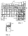
- the end walls 14 of the base 11 have a plurality of recesses 32, shown in Figures 4 and 7, that receive pintles 37 of the end panels 18.
- the recesses 32 have flanges 33 at opposite ends of the recesses that are cantilevered and adapted to be resiliently deformed as the pintles 37 are forced into the recesses.
- the pintles 37 have pins 38 that flex the flanges 33 outwardly as the pintle is driven downwardly into the recess.
- the pins 38 are forced downwardly into the recesses beyond the ends of the flanges so that the flanges snap or flex back into position to capture the pins and hold the pintles into the recesses.
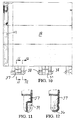
- the recesses have a rounded bottom wall surface 35 that receives a correspondingly shaped bearing surface 36 of the end panel pintles 37, as shown in Figures 11 and 12.
- This permits a smooth pivoting movement of the end panels when they are uprighted into a substantially vertical position for assembling the container for use.
- each of the pintles has an opening 39 between the pins that receives a corresponding buttress flange 34 formed on the end wall 14 of the base for strengthening the hinge joint against impact or forces applied from the exterior of the container.
- Figure 7 shows the end panels with pintles 37 engaged in the recesses 32 and an end panel 18 swung into a substantially vertical upright position.
- the end panels are swung into the vertical position first, and held in this position by a detent.
- a V-shaped rib 41 is provided along a bottom portion of the end panel to engage a correspondingly positioned groove 42 provided along a top portion of the base end wall. This prevents the end panels from falling once erected during final assembly of the container.
- the end panels have pockets 43 extending along an inwardly facing edge 44 of the panels that receive correspondingly shaped hooks 54 of the side panels 24, 25 to form corners 45, as shown in a top plan view, in Figure 14.
- the side panels are of a substantially similar construction, but side panel 25 differs from side panel 24 in that an opening is provided for a gate 60.
- the side panels have journal portions 47 with an elongated slot 48 to permit them to be raised vertically while being pivoted.
- the elongated slots 48 receive therein a hinge pin, not shown, that extends along hinge axis 46.
- the slot 48 is molded in the journal portions of the side panels by providing alternating oppositely facing U-shaped portions 48a and 48b, as shown in Figures 21 and 23.
- Each of the side panels is erected to assemble the container for use after the end panels 18 have been swung into their upright position.
- the corner joints are formed by engaging the hooks in the pockets, which requires no additional latching structure or tools.
- the hooks 54 of the side panels 18 are vertically aligned above the pockets 43 of the end panels, and then the end panels are dropped downwardly to securely seat the hooks into the pockets.
- the side panels are raised or moved outwardly from their hinged connection to the base as they are swung into their upright position. This movement is permitted since the elongated slots of the journal portions 47 allow relative movement of the side panels to occur in a direction perpendicular to hinge axis 46.
- lift pins 49 which protrude from each edge of the side panels, are received in tracks 50, which are formed along an interior portion of each of the end walls 14 of the base.
- Figures 7 and 16 show one of the tracks 50.
- the pins slide along the tracks lifting the panel upwardly to position the hooks above the corresponding pockets.
- Figure 16 the positions that the lift pins of the side panels take as the panels are uprighted are shown.
- the side panels lay flat along the bottom wall of the base with the lift pins in the position shown at 51.
- the pins move within the tracks to position 52, whereupon the hooks of the side panels are raised and brought into alignment with the pockets of the ends panels.
- the pins travel to the end 50a of the tracks causing them to drop downwardly to position 53, allowing the side panels to correspondingly drop downwardly and seat the hooks within the pockets.
- the hooks 54 have tapered or wedged lower portions 55 so that once the hooks have been seated within the pockets 43 of the side panels, the hooks are not easily displaced from the pockets.
- one side panel 25 has an opening 58 for receiving the gate 60.
- Pockets 65 are formed in the panel along each side of the opening 58. Adjacent each of the pockets is a flange 58a that the gate engages during closing.
- Figure 22 shows a cross-sectional view of pockets 65 and the flange 58a. The pockets receive corresponding hooks 61 formed along each edge of the gate in a manner similar to the way in which hooks 54 of the side panels 25, 26 are received within pockets 43 of the end panels 18.
- the gate 60 is hinged by a hinge member 63 journaled on two hinge pins, not shown.
- the hinge pins have first and second axes of rotation 62 and 64, respectively, shown in Figure 24.
- tab portions 68 formed along the bottom edge of the gate are provided to fix one of the hinge pins to the gate.
- side panel 25 has upstanding tab portions 59 along the bottom edge of the opening 58 to fix the other of the hinge pins to the side panel.
- the downward depending tab portions 68 are positioned at the interior side of the gate.
- the upstanding tab portions 59 are formed adjacent the exterior side of the panel, as shown in Figure 23.
- the hinge member 63 provides lost motion in the vertical direction to permit gate hooks 61 to enter in and withdraw from pockets 65 formed in the edges of the opening 58 of the side panels.
- the construction of the containers permits injection molding of each of the parts, and efficient production of the containers in the knock down state.
- the containers are assembled in the knock down state after molding by hinging the side panels to the side walls of the base.
- the gate is hinged to side panel 25 by means of hinge member 63
- the side panels are hinged to the base.
- the slots 40 of journal portions 47 of the side panels are aligned with the hinge pin axis 46 and thereafter a hinge pin is passed through to join the side panels to the base.
- Each of the side panels is laid flat against the base.
- the end panels are joined to the base portion by forcing the pintles 37 of the end panels 18 down into the recesses 32 formed along the end walls 14 of the base 13.
- the containers can be stacked on top of other assembled or unassembled containers.
- the corners of the base have corner posts 20 with outwardly facing L-shaped flanges 21 formed along an upper portion thereof.
- the corner feet of the base receive the L-shaped flanges 21 to permit aligned stacking of the containers.
- the corner feet can be stacked on top of an assembled container by engaging the top portions of the corners 45 formed between the side and end panels when the container is assembled for use.
- each of the runners extends from one foot, across a second foot to a third foot along each side of the base and across the middle of the base. In this way, the runners extend around the perimeter of the base of the container and also across the middle for ensuring a uniform ground engaging support surface that can withstand sliding contact with uneven floors.
- the feet 17 of the container permit forklift entry and handling of the containers.
- a hit plate 85 having apertures 86 is fixed to the walls of the feet.
- the hit plate is shown in Figures 31 and 32, and is mounted to each of the corner feet by conventional fasteners, such as screws, not shown,
- mounting holes 87 shown in Figures 7, 15 and 16, are molded in the side walls of the feet in positions corresponding to the apertures 86 of the hit plate.
- cover plates 90 having snap hooks 91 are provided to cover the openings in the bottom wall 16 of base 11 where the feet are located.
- the snap hooks are received within apertures 76 formed in bottom wall 16 adjacent the feet 17.
- a shoulder 90a of each snap hook is dimensioned to engage a lip 76a adjacent each aperture 76 underneath the bottom wall 16 of the base, as shown in Figure 29.
- eight snap hooks are used to secure the cover plates to the bottom wall for covering the openings of the feet 17.
Abstract
A knock down bulk container (10) has side and end panels (24,25,18) hinged to a base (11). In assembling the container (10) for use, first the end panels (18) are uprighted to a substantially vertical position, and then the side panels (24,25) are swung to an upright position. As the side panels (24,25) are swung into their upright position, lift pins (38) formed to protrude laterally outwardly from each side edge of the side panels engage a lift track (50) in an end wall (14) of the base (11) to raise each of the side panels (24,25) vertically with respect to its hinge axis. To connect the panels together, the end panels (18) are formed with pockets (43) along their edges adjacent the corners of the container, and the side panels (24,25) have hooks (54) that are seated within the pockets (43) of the end panels (18). As the side panels (24,25) are swung into their upright position, the hooks (54) are positioned vertically above the pockets (43) by the engagement of the lift pins (38) with the tracks (50). Once in the vertical position, the lift pins (38) disengage from the tracks (50) and the side panels (24,25) drop downwardly to seat the hooks (54) within the pockets (43) to form the corners of the container.
Description
- The present invention relates to a bulk container having a base with aide and end panels that are pivotally mounted to the base. The panels lie flat during shipment, and then are uprighted and joined at their corners to form end and side walls of the container when the container is assembled for use. The container is stackable during shipment in its unassembled state and stackable in use, and further assembled and unassembled containers can be interstacked.
- Knock down bulk containers are known, and have the advantage that the side and end walls of the container can be erected when the container is to be used, but otherwise the container can be shipped or stored in an unassembled state to save space.
- Conventional bulk containers of the knock down type suffer from many disadvantages, particularly with regard to manufacturing the container in a minimum number of pieces that can be efficiently assembled together, both in the initial assembly of the container when it is formed in the knock down state, and in the final steps of assembly when the container is erected for use. The container parts are molded of a synthetic resin material. In the initial assembly steps, the side and end panels are hinged to the base along its edges. These hinged joints must then function to permit the side and end panels to be swung into an upright position in the steps performed later to assemble the container for use. Furthermore, the hinged joints must withstand the loading forces of the material contained within the bulk box once it is assembled.
- Knock down or collapsible type containers also suffer from the disadvantage that they are difficult to assemble when they are ready to be used. In particular, the connecting structure provided to form the corner joints is frequently difficult to assemble in that more than one person is required to complete the task, thereby detracting from the efficient assembly of the container by the end user.
- The invention relates to a bulk container that is shipped and stored in a knock down state and assembled when needed for use as a container. The side and end walls are pivotally mounted to the base along the edges of the base. A full sized container can be formed by erecting each of the side and end wall panels of the container to their upright position, and by joining the adjacent panels together at the corners of the container.
- The end and side walls of the container are pivotally mounted to the base along the edges of the base so that the container can be easily formed or assembled by uprighting the walls. Preferably, the first set of panels to be uprighted remain erect while the second set of walls is uprighted by providing a detent structure between the first set of panels and the base.
- The corner joints of the bulk container are formed with interengaging hook and pocket corner connectors. The hooks of one set of panels enter the pockets of another set of panels vertically and are seated within the pockets by continued relative vertical movement of one set of panels with respect to the other. It is preferred that the second set of panels to be erected engage a cam surface or track so that the panels are raised vertically with respect to the base as they are swung into the erected position. This causes the hooks to be raised into position in vertical alignment with the pockets. Then, when the second panels are fully uprighted, the panels disengage the cam surface or track so that the hooks fully engage with the pockets to form the corners of the container. Further, each of the hooks has a tapered or wedge shaped terminal portion that engages the pocket in which it is seated to secure them together.
- A gate in one side wall provides access to the interior of the container when the container is in the middle of a stack of several containers. The gate can be opened without requiring a latch to be operated in order to open the gate. The gate is further mounted by a hinge element to one of the panels so that when the gate is opened and access is provided into the interior of the container, the gate hangs downwardly flush or coplanar with the side wall or panel to which it is mounted.
- The base of the bulk container is suitable for handling with a forklift. In particular, with respect to synthetic resin molding of the base, the feet that engage the surface on which the container is supported are cored from the top and have metal reinforcing straps extending along their ground engaging surfaces. Preferably, each of the reinforcing straps is manufactured of a uniform length and secured to span the feet of the base of the container after the container base has been molded. Furthermore, in order to accommodate handling by a forklift, the sides of the foot are preferably reinforced by metal strike plates that reinforce the feet from possible damage caused by impact with the tines of a forklift.
- The bulk containers can be stacked on one another whether assembled for use or unassembled in the knock down state by providing L-shaped corner flanges that open outwardly at the top of each of the corners of the container. The corner flanges are provided at upper portions of corner posts of the base for stacking unassembled containers or containers in the knock down state, and at the corners formed between adjacent upper portions of the side and end walls of the base for stacking fully assembled containers. The feet at the corner portions of the base have bottom structure that cooperates or engages with the L-shaped flanges to permit the stocking of both assembled and unassembled containers.
- Figure 1 is a perspective view of two assembled bulk containers constructed according to an embodiment of the present invention with a third unassembled bulk container stacked on top;
- Figure 2 is a partial plan view of the base of the bulk container showing details of one half of each of the side and end walls and one quarter of the bottom wall of the base with the remainder of each wall not shown, but being constructed in mirror image thereof;
- Figure 3 is a reverse plan view of a portion of the base with respect to Figure 2;
- Figures 4, 5 and 6 are partial sectional views of the end wall of the base taken along lines 4-4, 5-5 and 6-6 of Figure 2, respectively;
- Figure 7 is an end elevational view showing a portion of the end wall of the base with a bottom portion of part of an end panel shown connected thereto;
- Figure 8 is a sectional view taken along line 8-8 of Figure 7;
- Figure 9 is a view of one half of an end panel in elevation;
- Figure 10 is a reverse view with respect to Figure 9 of one half of an end panel in elevation;
- Figures 11 and 12 are partial sectional views taken along lines 11-11 and 12-12 of Figure 10, respectively;
- Figure 13 is a side view of the end panel shown in Figure 9;
- Figure 14 is a top view of an end panel according to Figure 9 joined to a side panel at a corner of the bulk box;
- Figure 15 is a side elevational view of one half of the side wall of the base;
- Figures 16 and 17 are partial sectional views of the side wall of the base taken along lines 16-16 and 17-17 of Figure 15, respectively;
- Figure 18 is a view in elevation of one half of one side panel of the bulk box;
- Figure 19 is a side view in elevation of the side panel shown in Figure 18;
- Figure 20 is a view in elevation of one half of another side panel of the bulk box having a drop gate opening;
- Figures 21, 22 and 23 are partial sectional views taken along lines 21-21, 22-22 and 23-23, respectively, of Figure 20;
- Figure 24 is a view in elevation of one half of the drop gate that is hinged to the side panel shown in Figure 20 with a hinge member;
- Figures 25, 26 and 27 are partial sectional views taken along lines 25-25, 26-26 and 27-27 of Figure 24, respectively;
- Figure 28 is a sectional view of a portion of the base taken along line 28-28 of Figure 2;
- Figure 29 is a plan view of a runner mounted to the base of the bulk box;
- Figure 30 is a sectional view taken along line 30-30 in Figure 29;
- Figure 31 is a plan view of a hit plate mounted on a foot of the base of the bulk box;
- Figure 32 is an end view, partially in section, of the hit plate shown in Figure 31;
- Figure 33 is a plan view of a cover plate mounted to cover an opening of a foot in the bottom wall of the bulk box; and
- Figure 34 is a side view of the cover plate shown in Figure 33.
- Figure 1 is a perspective view of three knock down
bulk containers 10 of the present invention wherein the uppermost container is in the knocked-down or unassembled state and the bottom two containers have bean erected for use. - The containers have an open top, a base 11, end walls formed of
end panels 18 that are substantially similar, and side walls formed ofsimilar side panels Side panel 25 has agate 60 that allows access to the interior of the container when another container is stacked on top, as shown in Figure 1. - The base 11 of the container has a
bottom wall 16, as shown in Figures 2 and 3, oppositely facingend walls 14 and oppositely facingside walls 15 adjacent the end walls. The base also hasfeet 17. Figure 2 shows an interior view of the base andbottom wall 16 and Figure 3 shows an exterior view of the base andbottom wall 16. It is understood that each of Figures 2 and 3 show only one-fourth of the base structure, with the remainder being in mirror image of the quarter portion shown. Preferably, for example, it is apparent that ninefeet 17 are provided for supporting the container. - Preferably, the container is manufactured from injection molded synthetic resin in parts that are initially assembled together in the knocked-down state, shown at the top of the stack of containers in Figure 1. The
end panels 18 andside panels end walls 14 andside walls 15 of the base, respectively, so that the panels can be uprighted by swinging them into a substantially vertical position. By the present invention, discussed in greater detail herein, the corner joints between the panels are formed by merely swinging the side panels into position with respect to the end panels after the end panels have been erected. - The
end walls 14 of the base 11 have a plurality ofrecesses 32, shown in Figures 4 and 7, that receivepintles 37 of theend panels 18. Therecesses 32 haveflanges 33 at opposite ends of the recesses that are cantilevered and adapted to be resiliently deformed as thepintles 37 are forced into the recesses. In particular, thepintles 37 havepins 38 that flex theflanges 33 outwardly as the pintle is driven downwardly into the recess. As shown in Figure 7, thepins 38 are forced downwardly into the recesses beyond the ends of the flanges so that the flanges snap or flex back into position to capture the pins and hold the pintles into the recesses. - As shown in Figures 5 and 6, the recesses have a rounded bottom wall surface 35 that receives a correspondingly shaped bearing
surface 36 of theend panel pintles 37, as shown in Figures 11 and 12. This permits a smooth pivoting movement of the end panels when they are uprighted into a substantially vertical position for assembling the container for use. As further shown in Figures 11 and 12, each of the pintles has anopening 39 between the pins that receives a corresponding buttressflange 34 formed on theend wall 14 of the base for strengthening the hinge joint against impact or forces applied from the exterior of the container. - Figure 7 shows the end panels with
pintles 37 engaged in therecesses 32 and anend panel 18 swung into a substantially vertical upright position. In assembling the container for use, the end panels are swung into the vertical position first, and held in this position by a detent. For example, a V-shapedrib 41 is provided along a bottom portion of the end panel to engage a correspondingly positionedgroove 42 provided along a top portion of the base end wall. This prevents the end panels from falling once erected during final assembly of the container. - As shown in Figures 9, 10, 13 and 14, the end panels have
pockets 43 extending along an inwardly facing edge 44 of the panels that receive correspondingly shaped hooks 54 of theside panels corners 45, as shown in a top plan view, in Figure 14. - The side panels are of a substantially similar construction, but
side panel 25 differs fromside panel 24 in that an opening is provided for agate 60. The side panels havejournal portions 47 with anelongated slot 48 to permit them to be raised vertically while being pivoted. Theelongated slots 48 receive therein a hinge pin, not shown, that extends alonghinge axis 46. Theslot 48 is molded in the journal portions of the side panels by providing alternating oppositely facingU-shaped portions 48a and 48b, as shown in Figures 21 and 23. When the side panels are erected to extend substantially vertical, thejournal portions 47 are received withinrecesses 12 formed in theside walls 15 of the base 11, as shown in Figures 15, 16 and 17. - Each of the side panels is erected to assemble the container for use after the
end panels 18 have been swung into their upright position. The corner joints are formed by engaging the hooks in the pockets, which requires no additional latching structure or tools. To form thecorners 45 of the container, thehooks 54 of theside panels 18 are vertically aligned above thepockets 43 of the end panels, and then the end panels are dropped downwardly to securely seat the hooks into the pockets. - To align the hooks vertically above the pockets, the side panels are raised or moved outwardly from their hinged connection to the base as they are swung into their upright position. This movement is permitted since the elongated slots of the
journal portions 47 allow relative movement of the side panels to occur in a direction perpendicular to hingeaxis 46. To raise the side panels as they are uprighted, lift pins 49, which protrude from each edge of the side panels, are received in tracks 50, which are formed along an interior portion of each of theend walls 14 of the base. - Figures 7 and 16 show one of the tracks 50. As a side panel is uprighted, the pins slide along the tracks lifting the panel upwardly to position the hooks above the corresponding pockets. In Figure 16, the positions that the lift pins of the side panels take as the panels are uprighted are shown. Initially, the side panels lay flat along the bottom wall of the base with the lift pins in the position shown at 51. As the panels are swung upwardly, the pins move within the tracks to position 52, whereupon the hooks of the side panels are raised and brought into alignment with the pockets of the ends panels. Then, the pins travel to the
end 50a of the tracks causing them to drop downwardly toposition 53, allowing the side panels to correspondingly drop downwardly and seat the hooks within the pockets. Thehooks 54 have tapered or wedgedlower portions 55 so that once the hooks have been seated within thepockets 43 of the side panels, the hooks are not easily displaced from the pockets. - As shown in Figure 29, one
side panel 25 has anopening 58 for receiving thegate 60.Pockets 65 are formed in the panel along each side of theopening 58. Adjacent each of the pockets is aflange 58a that the gate engages during closing. Figure 22 shows a cross-sectional view ofpockets 65 and theflange 58a. The pockets receive corresponding hooks 61 formed along each edge of the gate in a manner similar to the way in which hooks 54 of theside panels pockets 43 of theend panels 18. - The
gate 60 is hinged by ahinge member 63 journaled on two hinge pins, not shown. The hinge pins have first and second axes ofrotation 62 and 64, respectively, shown in Figure 24. Dependingtab portions 68 formed along the bottom edge of the gate are provided to fix one of the hinge pins to the gate. Similarly,side panel 25 hasupstanding tab portions 59 along the bottom edge of theopening 58 to fix the other of the hinge pins to the side panel. - As shown in Figures 1, 25 and 26, the downward depending
tab portions 68 are positioned at the interior side of the gate. On the other hand, theupstanding tab portions 59 are formed adjacent the exterior side of the panel, as shown in Figure 23. Thus, thehinge member 63 provides lost motion in the vertical direction to permit gate hooks 61 to enter in and withdraw frompockets 65 formed in the edges of theopening 58 of the side panels. - The construction of the containers permits injection molding of each of the parts, and efficient production of the containers in the knock down state. In particular, as shown in Figure 1, the containers are assembled in the knock down state after molding by hinging the side panels to the side walls of the base. After the gate is hinged to
side panel 25 by means ofhinge member 63, the side panels are hinged to the base. Specifically, the slots 40 ofjournal portions 47 of the side panels are aligned with thehinge pin axis 46 and thereafter a hinge pin is passed through to join the side panels to the base. Each of the side panels is laid flat against the base. Then, the end panels are joined to the base portion by forcing thepintles 37 of theend panels 18 down into therecesses 32 formed along theend walls 14 of the base 13. - The containers can be stacked on top of other assembled or unassembled containers. To permit stacking of containers in the knock down state, the corners of the base have
corner posts 20 with outwardly facing L-shapedflanges 21 formed along an upper portion thereof. The corner feet of the base receive the L-shapedflanges 21 to permit aligned stacking of the containers. Furthermore, the corner feet can be stacked on top of an assembled container by engaging the top portions of thecorners 45 formed between the side and end panels when the container is assembled for use. - In Figure 28, a cross section of one of the
container feet 17 is shown. The feet are molded by being cored from the top so that the exterior of each foot has a contoured surface that engages the floor or other surface. This increases the load and impact resistance of the feet. Further, between each of the feet is arunner 80 havingapertures 80a, as shown in Figures 29 and 30. The runners are attached to the feet to fit withingrooves 74 that match the cross sectional shape of the runner by conventional fasteners that extend through apertures into mountingholes 74a formed in the bottom walls of the feet. As shown in Figures 1 and 3, each of the runners extends from one foot, across a second foot to a third foot along each side of the base and across the middle of the base. In this way, the runners extend around the perimeter of the base of the container and also across the middle for ensuring a uniform ground engaging support surface that can withstand sliding contact with uneven floors. - The
feet 17 of the container permit forklift entry and handling of the containers. To support thefeet 17 at the corners of the container against impact from the tines of the forklift, ahit plate 85 havingapertures 86 is fixed to the walls of the feet. The hit plate is shown in Figures 31 and 32, and is mounted to each of the corner feet by conventional fasteners, such as screws, not shown, For this purpose, mountingholes 87, shown in Figures 7, 15 and 16, are molded in the side walls of the feet in positions corresponding to theapertures 86 of the hit plate. - As shown in Figures 33 and 34,
cover plates 90 having snap hooks 91 are provided to cover the openings in thebottom wall 16 of base 11 where the feet are located. The snap hooks are received withinapertures 76 formed inbottom wall 16 adjacent thefeet 17. Specifically, ashoulder 90a of each snap hook is dimensioned to engage a lip 76a adjacent eachaperture 76 underneath thebottom wall 16 of the base, as shown in Figure 29. Preferably, eight snap hooks are used to secure the cover plates to the bottom wall for covering the openings of thefeet 17. - While a preferred embodiment has bean described structurally and functionally in detail for the advantages thereof, other embodiments, modifications and variations are contemplated within the broad aspects of the present invention, all of which are defined by the spirit and scope of the following claims.
Claims (10)
- A container (10) having a base (11) with base side (15) and end walls (15, 14), a pair of container end walls and a pair of container side walls wherein the container side and end walls are panels (18, 24, 25) pivotally mounted to the base (11) to lie substantially parallel with the base (11) in an unassembled position and are swung into an upright position and joined at adjacent vertical edges to form corners (20) of the container, comprising:
one of said pairs of side and end panels (18) being hinged to a respective pair of base side and end walls (14) for being first swung into an upright position;
the other of said pairs of side and end panels (24, 25) being mounted to said other of said base side and end walls (15) by hinge means (47, 46) providing lost motion in a direction perpendicular to a hinge axis (46) of said hinge means;
said one pair of panels (18) having inwardly facing pockets (43) formed along each vertically extending edge (44) and said other pair of panels (24, 25) having outwardly facing hooks (54) corresponding in position to said pockets (43) formed along each vertically extending edge (44) for engaging said pockets (43), said pockets (43) receiving said hooks (54) when said one pair of panels (18) has been erected and said other pair of panels (24, 25) has been uprighted to be substantially vertical, said hooks (54) being seated within said pockets (43) by downward movement of said other pair of panels (24, 25) with respect to said one pair of panels (18) and said base as permitted by said hinge means (47, 48); and
means for lifting (49, 50) said other pair of panels (24, 25) to raise each of said other pair of panels (24, 25) as each is swung into an upright position so that said hooks (54) are positioned vertically above said pockets (43), and said means for lifting (48, 50) permitting the lowering of said other pair of panels (24, 25) with respect to said one pair of panels (18) when said hooks (54) and pockets (43) are aligned with one another to allow said hooks (54) to be seated within said pockets (43) whereby the corners (20) of said container (11) are formed. - The container according to claim 1, wherein said lifting means (49, 50) comprises laterally extending pins (49) extending outwardly from each of said vertically extending edges of each of said other pair of panels (24, 25) and groove means (50) formed in the base (11) adjacent to each of said laterally extending pins (49) for receiving said pins (49) and lifting said panels (24, 25) with respect to said base (11) as said panels are swung into an erected position.
- The container according to claim 1, further comprising each of said one pair of panels (18) being snapped into engagement with a corresponding base side or end wall (15, 14); said panels having a pintle body (37) extending downwardly and having two laterally extending pins (38) extending outwardly therefrom; and said corresponding base wall (14) having a recess (32) for each of said pintle bodies with resilient deformable flanges (33) that engage said pins (38) as said pintle body (37) is forced downwardly into said recess (32), said pins (38) resiliently forcing said flanges (33) apart until said pins (38) pass said flanges (33) allowing them to flex inwardly toward one another to engage said pintle body (37) and said pins (38) therein between for preventing said pintle body (37) from being disengaged from said recess (32).
- A container according to claim 3, wherein said base (11) has a buttress flange (34) extending upwardly within said recess (32) for buttressing said pintle body (37) to reinforce said hinge means (47, 48).
- The container according to claim 4, wherein said pintle body (37) has an opening (39) between said pins (38) for receiving said buttress flange (33) and has a rounded bottom base (36) engagement surface adjacent each of said pins for engaging a corresponding rounded surface (35) of said base end wall (14) to permit one pair of said panels (18) to be rotated with said surfaces (35, 36) engaging.
- A container according to claim 1, wherein said base (11) has upstanding corner posts (20) at each of the corners of the base with outwardly facing L-shaped flanges (21) and said base (11) having feet (17) at each of said corners at a bottom portion of the base, wherein said L-shaped flanges (21) receive corresponding structure of said foot (17) for permitting stacking of said containers (11) in an unassembled state; and
each of said corners (20) of an assembled container having an outwardly facing L-shaped corner structure to permit interstacking of assembled and unassembled containers. - A container according to claim 1, wherein said other of said pair of end and side panels (25) has a drop gate (60) hingedly mounted to the panel (25) for permitting access to an interior of the container (11), said drop gate having means for engaging said panel along its edges (54, 61) for securing said drop gate to said panel without a latch.
- A container according to claim 1, further comprising:
said container being molded of a synthetic resin material and having a plurality of feet (22) extending downwardly from said base that are mold cored from the top to leave open top portions of the feet in a bottom wall (16) of the base (11); and
a plurality of cover plates (90) having means for mounting said cover plates to said bottom wall (91, 76) of the base to cover said open top portions.
- A container according to claim 8, further comprising:
a plurality of runners (80) extending between predetermined ones of said feet (22), each of said runners (80) being of a uniform length and having a cross-sectional shape; and
each of said feet (22) having a shape (74) in its bottom wall matching said cross-sectional shape for receiving said runners. - A container according to claim 8, wherein each of said feet (22) at the corners of said container has a hit plate (85) mounted on its exterior walls.
Applications Claiming Priority (2)
| Application Number | Priority Date | Filing Date | Title |
|---|---|---|---|
| US609719 | 1990-11-13 | ||
| US07/609,719 US5094356A (en) | 1990-11-13 | 1990-11-13 | Knock down bulk container |
Publications (1)
| Publication Number | Publication Date |
|---|---|
| EP0485672A1 true EP0485672A1 (en) | 1992-05-20 |
Family
ID=24442046
Family Applications (1)
| Application Number | Title | Priority Date | Filing Date |
|---|---|---|---|
| EP90312487A Withdrawn EP0485672A1 (en) | 1990-11-13 | 1990-11-16 | Knock down bulk container |
Country Status (4)
| Country | Link |
|---|---|
| US (1) | US5094356A (en) |
| EP (1) | EP0485672A1 (en) |
| JP (1) | JPH04327170A (en) |
| CA (1) | CA2030157C (en) |
Cited By (16)
| Publication number | Priority date | Publication date | Assignee | Title |
|---|---|---|---|---|
| FR2762300A1 (en) * | 1997-04-22 | 1998-10-23 | Allibert Equipement | CONTAINER PROVIDED WITH A GATEWAY AND MANUFACTURING METHOD THEREOF |
| WO2000063084A1 (en) * | 1999-04-20 | 2000-10-26 | Bekuplast Kunststoffverarbeitungs-Gmbh | Transport and storage container with inward-folding side walls |
| US6409041B1 (en) | 2000-09-21 | 2002-06-25 | Rehrig Pacific Company | Container |
| US6631822B1 (en) | 2000-10-28 | 2003-10-14 | Rehrig Pacific Company | Collapsible container |
| US7331480B1 (en) | 2002-09-27 | 2008-02-19 | Roger Nolan | Articulated hinge apparatus and related methods |
| US7740149B2 (en) | 2002-09-27 | 2010-06-22 | Ropak Corporation | Container sidewall strengthening apparatus and methods |
| US8727165B2 (en) | 2007-08-15 | 2014-05-20 | Orbis Corporation | Hinge system for a modular bulk container |
| US8820560B2 (en) | 2009-12-16 | 2014-09-02 | Orbis Corporation | Collapsible bin |
| US8915397B2 (en) | 2012-11-01 | 2014-12-23 | Orbis Corporation | Bulk container with center support between drop door and side wall |
| US8950613B2 (en) | 2011-02-16 | 2015-02-10 | Orbis Corporation | Bulk bin container with removable side wall |
| US9422082B2 (en) | 2005-06-03 | 2016-08-23 | Roger Nolan | Container assembly and latch apparatus, and related methods |
| US9487326B2 (en) | 2013-11-26 | 2016-11-08 | Orbis Corporation | Bulk bin with panel to panel interlock features |
| US9708097B2 (en) | 2013-11-15 | 2017-07-18 | Orbis Corporation | Bulk bin with integrated shock absorber |
| US9863174B2 (en) | 2014-06-20 | 2018-01-09 | Orbis Corporation | Hinge rod trap for a collapsible bin |
| US10703531B2 (en) | 2016-03-11 | 2020-07-07 | Rehrig Pacific Company | Collapsible crate with wood appearance |
| US11597557B2 (en) | 2018-10-04 | 2023-03-07 | Rehrig Pacific Company | Reconfigurable beverage crate |
Families Citing this family (78)
| Publication number | Priority date | Publication date | Assignee | Title |
|---|---|---|---|---|
| US5501351A (en) * | 1992-07-17 | 1996-03-26 | Minnesota Mining And Manufacturing Company | Reusable, multiple-piece storage container |
| US5328048A (en) * | 1993-02-08 | 1994-07-12 | Otto Industries, Inc. | Tote box |
| FR2702198A1 (en) * | 1993-03-01 | 1994-09-09 | Raef Sarl Location | Folding crate for transporting fruit and vegetables |
| EP0629558B2 (en) † | 1993-06-07 | 2009-03-25 | Macroplastics, Inc. | Stackable container |
| US5467885A (en) * | 1993-11-29 | 1995-11-21 | Blinstrub; Robert M. | Collapsible material handling container |
| US5398835A (en) * | 1993-11-29 | 1995-03-21 | Blinstrub; Robert M. | Collapsible material handling container having improved corner interlock |
| US5586675A (en) * | 1993-11-29 | 1996-12-24 | General Electric Company | Reinforced material handling container |
| EP0690003A1 (en) | 1993-11-29 | 1996-01-03 | Otto Industries, Inc. | Collapsible container |
| US6010022A (en) * | 1994-05-18 | 2000-01-04 | Buckhorn, Inc. | Dispensing box for flowable material |
| US5845799A (en) * | 1994-05-18 | 1998-12-08 | Buckhorn Material Handling Group, Inc. | Dispensing gate for knock down bulk box |
| DE69637919D1 (en) * | 1995-06-07 | 2009-06-18 | Orbis Corp | COMPATIBLE CONTAINER WITH ANCHORED SIDE WALLS |
| GB2330826B (en) * | 1995-07-26 | 2000-02-16 | Mckechnie Uk Ltd | Collapsible container |
| US5722550A (en) * | 1996-06-06 | 1998-03-03 | Buckhorn Material Handling Group, Inc. | Container having reusable base and disposable over sleeve |
| WO1997049613A1 (en) * | 1996-06-24 | 1997-12-31 | Schoeller International Engineering S.A. | Hinge and lock for the side walls of a box-shaped collapsible container |
| BE1010646A3 (en) * | 1996-09-24 | 1998-11-03 | Overpelt Plascobel Nv | Folding crate |
| CA2228541C (en) * | 1997-02-07 | 2006-04-18 | Hans Umiker | Folding container with detachable lockable side walls |
| US6601724B1 (en) * | 1999-11-20 | 2003-08-05 | Rehrig Pacific Company | Collapsible merchandizing container |
| US6142329A (en) | 2000-01-31 | 2000-11-07 | Dolav Dvir Lahav Plastic Products | Knock-down bin |
| US6416271B1 (en) | 2000-04-07 | 2002-07-09 | Nucon Corporation | Drop box container |
| US6631821B2 (en) | 2000-10-31 | 2003-10-14 | Peter N. Vourganas | Reinforced double-wall knock-down bin |
| US20020108950A1 (en) * | 2001-02-14 | 2002-08-15 | Moorman Stephen E. | Collapsible container |
| US7104414B2 (en) * | 2002-01-12 | 2006-09-12 | Rehrig Pacific Company | Collapsible container |
| US7059489B2 (en) * | 2002-10-11 | 2006-06-13 | Rehrig Pacific Company | Portable storage device |
| US6966449B2 (en) * | 2003-01-02 | 2005-11-22 | The Little Tikes Company | Bulk box |
| US7017766B2 (en) * | 2003-03-10 | 2006-03-28 | Rehrig Pacific Company | Collapsible container with side wall latching capability |
| US7100786B2 (en) * | 2003-03-21 | 2006-09-05 | Rehrig Pacific Company | Collapsible container |
| US7195127B2 (en) * | 2003-05-13 | 2007-03-27 | Rehrig Pacific Company | Collapsible container |
| US20050150892A1 (en) * | 2004-01-09 | 2005-07-14 | Miller Daniel R. | Collapsible container having recessed lid locking latches |
| US7475526B2 (en) * | 2004-04-19 | 2009-01-13 | Polymer Logistics (Israel) Ltd. | Knock-down crate with walls stored in base and method employing such a crate |
| EP1737737B1 (en) | 2004-04-19 | 2010-03-17 | Polymer Logistics (Israel) Ltd. | Knock-down crate with walls stored in base and method employing such a crate |
| JP4540531B2 (en) * | 2005-04-20 | 2010-09-08 | 三甲株式会社 | Box pallet |
| US7484634B2 (en) * | 2005-05-17 | 2009-02-03 | Rehrig Pacific Company | Container with collapsible wall |
| AU2006203690A1 (en) * | 2005-09-09 | 2007-03-29 | Fuvi Mechanical Technology Company Limited | An Assemble/Diassemble Type Container |
| US20070095842A1 (en) * | 2005-11-01 | 2007-05-03 | Apps William P | Container |
| US7357269B2 (en) * | 2005-11-01 | 2008-04-15 | Rehrig Pacific Company | Container |
| US7748329B2 (en) * | 2006-07-24 | 2010-07-06 | Rehrig Pacific Company | Pallet assembly |
| US20080083636A1 (en) * | 2006-10-10 | 2008-04-10 | Devine Timothy A | Stackable plant carrying system |
| US20080116201A1 (en) * | 2006-11-17 | 2008-05-22 | Kyle Baltz | Container |
| US20080169285A1 (en) * | 2007-01-16 | 2008-07-17 | Nick Marazita | Collapsible container |
| US7641066B2 (en) * | 2007-06-11 | 2010-01-05 | Rehrig Pacific Company | Collapsible container |
| US8137043B2 (en) * | 2007-09-10 | 2012-03-20 | Beck Tom J | Device for opening and closing the discharge door of a bulk seed box |
| US7717283B2 (en) * | 2007-11-06 | 2010-05-18 | Rehrig Pacific Company | Collapsible container |
| US8720692B2 (en) * | 2007-11-21 | 2014-05-13 | Rehrig Pacific Company | Pallet |
| US7861458B2 (en) * | 2007-12-13 | 2011-01-04 | Rehrig Pacific Company | Collapsible container |
| US20090159593A1 (en) * | 2007-12-21 | 2009-06-25 | Apps William P | Collapsible container |
| US20100072199A1 (en) * | 2008-09-24 | 2010-03-25 | Nathan Manuel | Collapsible bin |
| US8851822B2 (en) * | 2009-02-17 | 2014-10-07 | C & B Manufacturing | Seed cart |
| US8961098B2 (en) | 2009-02-17 | 2015-02-24 | Chad Mohns | Seed cart |
| DE102009049184A1 (en) | 2009-04-15 | 2010-11-04 | Ifco Systems Gmbh | Crate with foldable side walls and locking mechanisms with overload protection |
| DE102009049186A1 (en) | 2009-04-15 | 2010-11-04 | Ifco Systems Gmbh | Crate with foldable and self-locking side walls |
| DE102009049103A1 (en) | 2009-04-15 | 2010-11-04 | Ifco Systems Gmbh | Crate with foldable and removable outer walls |
| DK2408677T3 (en) * | 2009-04-15 | 2013-04-22 | Ifco Systems Gmbh | Container with foldable side wall |
| US8240494B1 (en) | 2009-07-30 | 2012-08-14 | Brad Mohns | Bulk material container with adaptable base |
| US8083083B1 (en) | 2009-07-30 | 2011-12-27 | Brad Mohns | Bulk material container with adaptable base |
| US8303236B2 (en) * | 2009-09-30 | 2012-11-06 | Beck Tom J | Bulk seed handling and dispensing system |
| EP2571775A1 (en) * | 2010-05-17 | 2013-03-27 | Schoeller Arca Systems GmbH | Plastics transport container, in particular transport box |
| EP2390199B1 (en) | 2010-05-27 | 2013-07-10 | Rehrig Pacific Company | Collapsible dual height stacking container |
| US8616370B2 (en) | 2010-10-28 | 2013-12-31 | Arrows Up, Inc. | Bulk material shipping container |
| US8887914B2 (en) | 2010-10-28 | 2014-11-18 | Arrows Up, Inc. | Bulk material shipping container |
| JP5627532B2 (en) | 2011-04-15 | 2014-11-19 | 三甲株式会社 | Box pallet and side wall of box pallet |
| CA2794108A1 (en) | 2011-11-09 | 2013-05-09 | Norduyn Inc. | Cargo pallet and method of manufacture thereof |
| US20140020927A1 (en) * | 2012-07-18 | 2014-01-23 | Checkers Industrial Products, Llc | Cable protector lid connection systems and methods |
| WO2014176578A1 (en) * | 2013-04-25 | 2014-10-30 | A.R. Arena Products, Inc. | Disassembleable cheese container with wrap-around interlock and increased fill volume |
| US9731864B2 (en) | 2013-05-13 | 2017-08-15 | Macro Plastics, Inc. | Shipping container and safety catch therefor |
| US9273506B1 (en) | 2013-07-15 | 2016-03-01 | Tom J. Beck | Device for opening and closing the discharge door of a bulk seed box |
| US9440787B1 (en) | 2013-08-27 | 2016-09-13 | Stacy W. Cochran | Platform for supporting and moving a bulk seed container or the like |
| US9580237B2 (en) * | 2013-09-09 | 2017-02-28 | Orbis Corporation | Collapsible hopper bin |
| JP2014156286A (en) * | 2014-04-25 | 2014-08-28 | Sanko Co Ltd | Raisable container |
| JP5883069B2 (en) * | 2014-05-21 | 2016-03-09 | 三甲株式会社 | Assembly / disassembly container |
| US10427837B2 (en) | 2015-04-20 | 2019-10-01 | Orbis Corporation | Container with feature to block fork tine openings |
| US10457444B2 (en) | 2016-05-24 | 2019-10-29 | Orbis Corporation | Bulk container with interlocking features |
| CA2945454C (en) | 2016-06-30 | 2023-11-07 | Arrows Up, Llc | Bulk material shipping container |
| US10994954B2 (en) | 2016-06-30 | 2021-05-04 | Sandbox Enterprises, Llc | Bulk material shipping container unloader |
| US10065763B2 (en) | 2016-09-15 | 2018-09-04 | Arena Packaging, Llc | Wall latching system |
| CN108860921B (en) * | 2018-08-08 | 2020-11-20 | 上海鸿研物流技术有限公司 | Collapsible container |
| US11661235B2 (en) | 2018-10-15 | 2023-05-30 | Sandbox Enterprises, Llc | Bulk material shipping container top wall assembly and bulk material shipping container having a top wall assembly |
| US10926940B2 (en) | 2018-11-20 | 2021-02-23 | Sandbox Enterprises, Llc | Bulk material shipping container |
| US11834258B2 (en) | 2021-09-03 | 2023-12-05 | A. R. Arena Products, Inc. | Intermediate bulk container systems and methods of using same |
Citations (3)
| Publication number | Priority date | Publication date | Assignee | Title |
|---|---|---|---|---|
| US3874546A (en) * | 1973-10-11 | 1975-04-01 | Pinckney Molded Plastic Inc | Convertible container-pallet |
| US4591065A (en) * | 1984-09-25 | 1986-05-27 | Foy Dennis M | Foldable container assembly |
| EP0281422A2 (en) * | 1987-03-06 | 1988-09-07 | Ropak Corporation | Collapsible container |
Family Cites Families (28)
| Publication number | Priority date | Publication date | Assignee | Title |
|---|---|---|---|---|
| US1155161A (en) * | 1915-06-17 | 1915-09-28 | Walter C Ramsey | Hinge. |
| US1358373A (en) * | 1920-04-17 | 1920-11-09 | Gust A F Johnson | Grain-car door |
| US1735696A (en) * | 1927-09-16 | 1929-11-12 | Ridley Alfred | Concealed hinge |
| GB826578A (en) * | 1957-01-11 | 1960-01-13 | B C Barton & Son Ltd | Improvements relating to stacking pallets or bins |
| FR1273689A (en) * | 1960-11-15 | 1961-10-13 | Crate-packing more particularly for fruits | |
| US3348723A (en) * | 1965-08-02 | 1967-10-24 | Banner Metals Inc | Receptacle |
| US3628683A (en) * | 1969-11-20 | 1971-12-21 | Wolfgang Erhard Friedrich | Collapsible box |
| US3796342A (en) * | 1972-06-05 | 1974-03-12 | Pinckney Molded Plastics | Collapsible container |
| FR2272907A1 (en) * | 1974-05-31 | 1975-12-26 | Allibert Exploitation | Collapsible box with sides hinged to base - has sides movable vertically to unlock hooks holding sides together |
| US4062467A (en) * | 1974-07-27 | 1977-12-13 | Friedrich Wolfgang E | Collapsible transport container |
| SU662432A1 (en) * | 1974-08-16 | 1979-05-15 | Kashevnik Boris L | Collapsible box |
| US3948190A (en) * | 1974-10-04 | 1976-04-06 | Oakland Plastics Corporation | Industrial load-carrying pallet |
| US3968895A (en) * | 1975-02-19 | 1976-07-13 | Richard R. Barnes, Jr. | Air cargo shipping container |
| FR2343110A1 (en) * | 1976-03-01 | 1977-09-30 | Reunis Sa Ateliers | LOCKING DEVICE INTENDED TO EQUIP THE WALLS OF A TRANSPORTER TROLLEY OR A RECEPTACLE OF GOODS OR SIMILAR |
| GB1529485A (en) * | 1976-08-12 | 1978-10-18 | Worldwide Plastics Dev | Collapsible container |
| GR64982B (en) * | 1977-10-04 | 1980-06-11 | Palbox Spa | Reception(receiver)made of inflated thermoplastic material for the carrying out and storage of goods in bulk,for example agricultural products |
| US4320845A (en) * | 1978-12-07 | 1982-03-23 | Waller John G | Collapsible container |
| US4192430A (en) * | 1979-03-12 | 1980-03-11 | Allibert Exploitation, Societe Anonyme | Laterally openable storage and transport box |
| US4466541A (en) * | 1982-04-26 | 1984-08-21 | Buckhorn Material Handling Group Inc. | Molded container with integral hinge |
| US4630746A (en) * | 1984-02-27 | 1986-12-23 | Fortenberry & Associates, Inc. | Collapsible stackable shipping container |
| US4674647A (en) * | 1985-06-21 | 1987-06-23 | Xytec Plastics, Inc. | Collapsible storage bin |
| US4673087A (en) * | 1985-11-04 | 1987-06-16 | Peninsula Plastics Co., Inc. | Collapsable, reusable container system |
| US4662532A (en) * | 1985-11-04 | 1987-05-05 | Steel King Industries, Inc. | Foldable container |
| US4735330A (en) * | 1987-03-02 | 1988-04-05 | Chrysler Motors Corporation | Collapsible bin |
| US4923079A (en) * | 1987-03-06 | 1990-05-08 | Ropak Corporation | Collapsible container |
| US4735331A (en) * | 1987-04-06 | 1988-04-05 | Chrysler Motors Corporation | Collapsible bin |
| US4775068A (en) * | 1988-01-11 | 1988-10-04 | Xytec Plastics, Inc. | Collapsible container with removable access panel |
| US4917255A (en) * | 1989-02-24 | 1990-04-17 | J.I.T. Corporation | Collapsible container |
-
1990
- 1990-11-13 US US07/609,719 patent/US5094356A/en not_active Expired - Lifetime
- 1990-11-16 EP EP90312487A patent/EP0485672A1/en not_active Withdrawn
- 1990-11-16 CA CA002030157A patent/CA2030157C/en not_active Expired - Lifetime
-
1991
- 1991-11-08 JP JP3293210A patent/JPH04327170A/en active Pending
Patent Citations (3)
| Publication number | Priority date | Publication date | Assignee | Title |
|---|---|---|---|---|
| US3874546A (en) * | 1973-10-11 | 1975-04-01 | Pinckney Molded Plastic Inc | Convertible container-pallet |
| US4591065A (en) * | 1984-09-25 | 1986-05-27 | Foy Dennis M | Foldable container assembly |
| EP0281422A2 (en) * | 1987-03-06 | 1988-09-07 | Ropak Corporation | Collapsible container |
Cited By (22)
| Publication number | Priority date | Publication date | Assignee | Title |
|---|---|---|---|---|
| EP0876963A1 (en) * | 1997-04-22 | 1998-11-11 | Allibert Equipement | Container provided with a flap and manufacturing method therefor |
| FR2762300A1 (en) * | 1997-04-22 | 1998-10-23 | Allibert Equipement | CONTAINER PROVIDED WITH A GATEWAY AND MANUFACTURING METHOD THEREOF |
| WO2000063084A1 (en) * | 1999-04-20 | 2000-10-26 | Bekuplast Kunststoffverarbeitungs-Gmbh | Transport and storage container with inward-folding side walls |
| US6409041B1 (en) | 2000-09-21 | 2002-06-25 | Rehrig Pacific Company | Container |
| US7086555B2 (en) | 2000-09-21 | 2006-08-08 | Rehrig Pacific Company | Container |
| US6631822B1 (en) | 2000-10-28 | 2003-10-14 | Rehrig Pacific Company | Collapsible container |
| US7128231B2 (en) | 2000-10-28 | 2006-10-31 | Rehrig Pacific Company | Collapsible container |
| US7331480B1 (en) | 2002-09-27 | 2008-02-19 | Roger Nolan | Articulated hinge apparatus and related methods |
| US7740149B2 (en) | 2002-09-27 | 2010-06-22 | Ropak Corporation | Container sidewall strengthening apparatus and methods |
| US7828167B2 (en) | 2002-09-27 | 2010-11-09 | Roger Nolan | Articulated hinge apparatus and related methods |
| US9422082B2 (en) | 2005-06-03 | 2016-08-23 | Roger Nolan | Container assembly and latch apparatus, and related methods |
| US8727165B2 (en) | 2007-08-15 | 2014-05-20 | Orbis Corporation | Hinge system for a modular bulk container |
| US9415898B2 (en) | 2009-12-16 | 2016-08-16 | Orbis Corporation | Bulk container with angled side wall to base installation |
| US8820560B2 (en) | 2009-12-16 | 2014-09-02 | Orbis Corporation | Collapsible bin |
| US8950613B2 (en) | 2011-02-16 | 2015-02-10 | Orbis Corporation | Bulk bin container with removable side wall |
| US8915397B2 (en) | 2012-11-01 | 2014-12-23 | Orbis Corporation | Bulk container with center support between drop door and side wall |
| US9296557B2 (en) | 2012-11-01 | 2016-03-29 | Orbis Corporation | Bulk container with center support between drop door and side wall |
| US9708097B2 (en) | 2013-11-15 | 2017-07-18 | Orbis Corporation | Bulk bin with integrated shock absorber |
| US9487326B2 (en) | 2013-11-26 | 2016-11-08 | Orbis Corporation | Bulk bin with panel to panel interlock features |
| US9863174B2 (en) | 2014-06-20 | 2018-01-09 | Orbis Corporation | Hinge rod trap for a collapsible bin |
| US10703531B2 (en) | 2016-03-11 | 2020-07-07 | Rehrig Pacific Company | Collapsible crate with wood appearance |
| US11597557B2 (en) | 2018-10-04 | 2023-03-07 | Rehrig Pacific Company | Reconfigurable beverage crate |
Also Published As
| Publication number | Publication date |
|---|---|
| JPH04327170A (en) | 1992-11-16 |
| US5094356A (en) | 1992-03-10 |
| CA2030157C (en) | 1996-06-04 |
| CA2030157A1 (en) | 1992-05-14 |
Similar Documents
| Publication | Publication Date | Title |
|---|---|---|
| EP0485672A1 (en) | Knock down bulk container | |
| US4674647A (en) | Collapsible storage bin | |
| US9296514B2 (en) | Collapsible container having foldable side and end panels | |
| US8820560B2 (en) | Collapsible bin | |
| KR100518772B1 (en) | A Stackable Knock Down Box | |
| US5415311A (en) | Collapsible storage containers | |
| US4630746A (en) | Collapsible stackable shipping container | |
| US4693386A (en) | Collapsible shipping container | |
| CA2340619C (en) | Collapsible container | |
| US6286701B1 (en) | Container, in particular for transporting fruits and vegetables | |
| CA1159379A (en) | Collapsible shipping container | |
| EP0218320B1 (en) | a frame structure | |
| EP0211116B1 (en) | Collapsible storage bin | |
| US8408411B2 (en) | Collapsible plastic container | |
| CA2279856C (en) | Container, in particular for transporting fruits and vegetables | |
| US20090114645A1 (en) | Articulate Collapsible Modular Container | |
| CA1302862C (en) | Removable and stackable hoistway door assembly | |
| US20120152799A1 (en) | Collapsible plastic container | |
| US4974737A (en) | Extension ring | |
| US5458255A (en) | Folding case for fruit and vegetables | |
| US20190270545A1 (en) | Collapsible container | |
| KR101484758B1 (en) | Side wall for assembly box and assembly box comprising the same | |
| JPH0513713Y2 (en) | ||
| JPH0526035Y2 (en) | ||
| JPH057147Y2 (en) |
Legal Events
| Date | Code | Title | Description |
|---|---|---|---|
| PUAI | Public reference made under article 153(3) epc to a published international application that has entered the european phase |
Free format text: ORIGINAL CODE: 0009012 |
|
| AK | Designated contracting states |
Kind code of ref document: A1 Designated state(s): AT BE CH DE DK ES FR GB GR IT LI LU NL SE |
|
| 17P | Request for examination filed |
Effective date: 19920925 |
|
| STAA | Information on the status of an ep patent application or granted ep patent |
Free format text: STATUS: THE APPLICATION HAS BEEN WITHDRAWN |
|
| 18W | Application withdrawn |
Withdrawal date: 19940914 |