EP0485555B1 - Plate evaporator - Google Patents
Plate evaporator Download PDFInfo
- Publication number
- EP0485555B1 EP0485555B1 EP91909728A EP91909728A EP0485555B1 EP 0485555 B1 EP0485555 B1 EP 0485555B1 EP 91909728 A EP91909728 A EP 91909728A EP 91909728 A EP91909728 A EP 91909728A EP 0485555 B1 EP0485555 B1 EP 0485555B1
- Authority
- EP
- European Patent Office
- Prior art keywords
- heat transfer
- fluid
- evaporating
- transfer plates
- passages
- Prior art date
- Legal status (The legal status is an assumption and is not a legal conclusion. Google has not performed a legal analysis and makes no representation as to the accuracy of the status listed.)
- Expired - Lifetime
Links
Images

Classifications
-
- F—MECHANICAL ENGINEERING; LIGHTING; HEATING; WEAPONS; BLASTING
- F28—HEAT EXCHANGE IN GENERAL
- F28F—DETAILS OF HEAT-EXCHANGE AND HEAT-TRANSFER APPARATUS, OF GENERAL APPLICATION
- F28F3/00—Plate-like or laminated elements; Assemblies of plate-like or laminated elements
- F28F3/02—Elements or assemblies thereof with means for increasing heat-transfer area, e.g. with fins, with recesses, with corrugations
- F28F3/04—Elements or assemblies thereof with means for increasing heat-transfer area, e.g. with fins, with recesses, with corrugations the means being integral with the element
- F28F3/042—Elements or assemblies thereof with means for increasing heat-transfer area, e.g. with fins, with recesses, with corrugations the means being integral with the element in the form of local deformations of the element
- F28F3/046—Elements or assemblies thereof with means for increasing heat-transfer area, e.g. with fins, with recesses, with corrugations the means being integral with the element in the form of local deformations of the element the deformations being linear, e.g. corrugations
-
- B—PERFORMING OPERATIONS; TRANSPORTING
- B01—PHYSICAL OR CHEMICAL PROCESSES OR APPARATUS IN GENERAL
- B01D—SEPARATION
- B01D1/00—Evaporating
- B01D1/22—Evaporating by bringing a thin layer of the liquid into contact with a heated surface
- B01D1/221—Composite plate evaporators
-
- F—MECHANICAL ENGINEERING; LIGHTING; HEATING; WEAPONS; BLASTING
- F28—HEAT EXCHANGE IN GENERAL
- F28F—DETAILS OF HEAT-EXCHANGE AND HEAT-TRANSFER APPARATUS, OF GENERAL APPLICATION
- F28F3/00—Plate-like or laminated elements; Assemblies of plate-like or laminated elements
- F28F3/08—Elements constructed for building-up into stacks, e.g. capable of being taken apart for cleaning
- F28F3/083—Elements constructed for building-up into stacks, e.g. capable of being taken apart for cleaning capable of being taken apart
-
- F—MECHANICAL ENGINEERING; LIGHTING; HEATING; WEAPONS; BLASTING
- F28—HEAT EXCHANGE IN GENERAL
- F28D—HEAT-EXCHANGE APPARATUS, NOT PROVIDED FOR IN ANOTHER SUBCLASS, IN WHICH THE HEAT-EXCHANGE MEDIA DO NOT COME INTO DIRECT CONTACT
- F28D21/00—Heat-exchange apparatus not covered by any of the groups F28D1/00 - F28D20/00
- F28D2021/0019—Other heat exchangers for particular applications; Heat exchange systems not otherwise provided for
- F28D2021/0061—Other heat exchangers for particular applications; Heat exchange systems not otherwise provided for for phase-change applications
- F28D2021/0066—Other heat exchangers for particular applications; Heat exchange systems not otherwise provided for for phase-change applications with combined condensation and evaporation
-
- F—MECHANICAL ENGINEERING; LIGHTING; HEATING; WEAPONS; BLASTING
- F28—HEAT EXCHANGE IN GENERAL
- F28F—DETAILS OF HEAT-EXCHANGE AND HEAT-TRANSFER APPARATUS, OF GENERAL APPLICATION
- F28F2215/00—Fins
- F28F2215/04—Assemblies of fins having different features, e.g. with different fin densities
-
- Y—GENERAL TAGGING OF NEW TECHNOLOGICAL DEVELOPMENTS; GENERAL TAGGING OF CROSS-SECTIONAL TECHNOLOGIES SPANNING OVER SEVERAL SECTIONS OF THE IPC; TECHNICAL SUBJECTS COVERED BY FORMER USPC CROSS-REFERENCE ART COLLECTIONS [XRACs] AND DIGESTS
- Y10—TECHNICAL SUBJECTS COVERED BY FORMER USPC
- Y10S—TECHNICAL SUBJECTS COVERED BY FORMER USPC CROSS-REFERENCE ART COLLECTIONS [XRACs] AND DIGESTS
- Y10S165/00—Heat exchange
- Y10S165/903—Convection
Definitions
- the present invention relates to a plate heat exchanger for evaporating a fluid, comprising a package of abutting rectangular and essentially vertically arranged heat transfer plates, delimiting flow spaces between themselves and provided with corrugation patterns of ridges and grooves, said ridges intersectingly abutting each other in at least a part of each flow space and forming a number of supporting points between adjacent heat transfer plates, wherein each alternate flow space forms an evaporating passage, which evaporating passage has an inlet for fluid at its lower portion and an outlet for fluid and generated vapour at its upper portion near one of the vertical sides of the heat transfer plates, and the remaining flow spaces form passages for a heating fluid, which passages have inlets at their upper portions near the other vertical sides of the heat transfer plates and outlets at their lower portions.
- each heat transfer plate has one and the same kind of corrugation pattern over its entire surface. This is ineffective with respect of the heat transfer capacity of the plate heat exchanger.
- an outlet duct for fluid and generated vapour extends further through the package of heat transfer plates, which outlet duct is formed of aligned openings of the heat transfer plates. The openings are made as great as possible to minimize the flow resistance in the outlet duct for the produced vapour. In practice a large part of the upper portion of each heat transfer plate has been used for such opening.
- An object of the present invention is to increase the efficiency of a plate heat exchanger of the kind described above, and to provide an uniform quality of the discharged fluid and generated vapour.
- a plate heat exchanger is characterised in that in each evaporating passage, close to its inlet for fluid, at least one heat transfer plate is provided with a plurality of zones having different corrugation pattern, arranged laterally adjacent to each other across the heat transfer plate between the vertical sides of the heat transfer plate, the ridges and grooves of the heat transfer plates in the area of said zones forming different angles against the main flow direction of the fluid in the evaporating passages, which angles are chosen in such a way that the ridges and grooves in consequence of their different direction cooperate to provide a flow resistance in each evaporating passage, in its main flow direction, which gradually decreases from said one to said other vertical side of the heat transfer plate.
- a fluid in a plate heat exchanger according to the invention, flows upwards through an evaporating passage and gradually evaporates, starting at one vertical side of the heat transfer plates, an increasing space is required for the produced vapour, in the evaporating passage close to said one side.
- the flowing fluid from below is forced to distribute across the evaporating passage such that a larger amount of fluid will flow near the other vertical side of the heat transfer plate, than in case of the evaporation of the fluid starting at the same level over the entire width of the heat transfer plate.
- the result is that the heat transfer surface of the heat transfer plates is used in the most efficient way.
- the risk of drying out in a part of each evaporating passage is reduced, owing to a larger amount of fluid than otherwise passing near the inlet of the heating fluid.
- the corrugation patterns of the heat transfer plates are designed such that the difference in flow resistance, caused by the ridges and grooves of the corrugation pattern, from said one to said other vertical side of the heat transfer plate is located mainly in the lower part of each evaporating passage, in which, during operation the supplied fluid has not yet evaporated to any important extent, while the corresponding difference in flow resistance is essentially lower or non-existant in other levels in each evaporating passage.
- a corrugation pattern of ridges and grooves being pressed in a heat transfer plate of the present kind will effect the flow of fluid on both sides of the heat transfer plate.
- a major part of the steam has already condensed.
- the plate heat exchanger shown in Fig. 1 comprises two kinds of rectangular, elongated heat transfer plates 1,2 which have been provided with different corrugation patterns by means of pressing.
- the heat transfer plates which are intended to be kept together in a frame (not shown) in a conventional manner, may be provided with rubber gaskets along their edges to delimit flow spaces 3 between them, but as an alternative they could be permanently joined to each other, e.g. through soldering, welding or gluing.
- the heat transfer plates 1 and 2 have been provided with a corrugation pattern of ridges and grooves by means of pressing, the ridges of two adjacent heat transfer plates in the flow spaces 3 crossing and abutting each other to form a number of supporting points between the heat transfer plates.
- Every second flow space 3 forms a passage 4 for evaporation of a fluid, which passage communicates with a fluid inlet 5 extending through a lower portion of the heat transfer plates and an outlet 6 for fluid and generated vapour, which extends through an upper portion of the heat transfer plates.
- Remaining flow spaces form second passages 7 for a heating fluid, which passages communicate with a steam inlet 8 extending through the upper portion of the heat transfer plates, and two condensate outlets 9 extending through the lower portion of the heat transfer plates.
- the heat exchanger shown in Fig. 1 is principally intended for evaporation or concentration of various liquid products by means of climbing film evaporation.
- the long sides of the heat transfer plates 1 and 2 are arranged vertically, and fluid to be evaporated is supplied to the passages 4 at their lower portion and discharged at their upper portion.
- the plate heat exchanger is arranged for use as a falling film evaporator with steam as heating medium supplied at the upper portion of the passages 7 and the condensate produced discharged at the lower portion of the passages 7.
- Each of the heat transfer plates 1 and 2 has a lower distribution portion 15, a heat transferring portion 16, divided in different horizontally extended portions 17, 18 and 19 having different corrugation patterns, and an upper distribution portion 20.
- the lower distribution portion 15 is arranged to convey fluid in each passage 4, essentially vertically upwards from the inlet 5 to the heat transfer portion 16, and in each passage 7, to convey the condensate both vertically downwards and horizontally towards the outlets 9.
- the upper distribution portion is formed in a manner which appears more closely in US 3783090.
- the lower horizontally extended portion 17 is divided into a number of zones 23, 24, 25 and 26 having different corrugation patterns, and being arranged adjacent to each other near to said inlet 5 for the fluid in each of the evaporating passages 4.
- the ridges and grooves in the zones 23, 24, 25 and 26 are directed in such a way that they cooperate to provide a flow resistance for the upwardly flowing fluid and generated vapour in each evaporating passage 4, which gradually decreases from one to the other of the vertical sides of the heat transfer plates.
- the heat transfer plates 1 and 2 shown in Figs. 2 and 3 have punched holes at each of their ends. These holes form a port 10A and 10B, respectively, at the bottom, for the fluid to be evaporated, a port 11A and 11B, respectively at the top, for concentrated fluid and generated vapour, a port 12A and 12B, respectively, at the top for heating steam and two ports 13A, 14A and 13B, 14B, respectively, at the bottom, for condensate and eventually uncondensed steam of the heating medium.
- the heat transfer plates 1 and 2 are further provided with lower distribution portions 15A and 15B, respectively, upper distribution portions 20A and 20B, respectively and heat transfer portions 16A and 16B, respectively, which latter are divided in different horizontally extended portions 17A, 18A, 19A and 17B, 18B, 19B, respectively, having different corrugation patterns.
- the lower portions 17A and 17B, respectively, of each plate are divided in different vertically extended zones 23A, 24A, 25A, 26A and 23B, 24B, 25B, 26B, respectively, having different corrugation patterns.
- the heat transfer plate 1 has on one of its sides a number of grooves 21 in which a unitary gasket is received.
- the gasket extends around each of the ports 10A and 10B and around the whole periphery of the plate.
- the heat exchange plate 2 has a number of grooves 22 accommodating a gasket extending around each of the ports 12B, 13B and 14B and around the whole periphery of the plate.
- the gaskets are arranged to seal between adjacent heat transfer plates 1 and 2.
- the gasket grooves can, as an alternative, be formed such that two adjacent plates may be welded together having the bottom of the grooves turned against each other, wherein only alternate plate interspaces are provided with gaskets which in such a case is located in confronting grooves in the adjacent heat transfer plates.
- the ridges and the grooves incline differently against the intended main flow direction of the fluid.
- the gradient decreases from one zone to another from below and upwards.
- Fluid which is to be completely or partly evaporated is supplied into the plate heat exchanger through the fluid inlet 5 which is located in the lower part of the heat transfer plates, and then flows upwards through the passage 4. Fluid is evenly distributed across the width of the heat transfer plates between the lower distribution portions 15A and 15B. Between the heat transfer portions 16A and 16B the fluid first passes the portions 17A and 17B, which include the four zones 23A, 24A, 25A, 26A and 23B, 24B, 25B, 26B, respectively.
- the zones 23A and 23B, located at one vertical side of the plate have a corrugation pattern providing a relatively great flow resistance in the evaporation passages 4 for upwardly flowing fluid, i.e. the ridges of the plates cross each other with a comparatively large intervening angle directed against the flow direction of the fluid.
- the heat transfer between the plates and the fluid becomes relatively efficient and consequently, vapour is generated relatively soon in these portions of the passages 4.
- the ridges and grooves incline differently against the intended main flow direction of the fluid.
- the gradient decreases from one zone to another from one to the other vertical side of each plate.
- an angle a of the plate 1 between the main flow direction of the fluid (shown with a vertical dash and dot line) and the direction of the corrugation ridges is -40° in the zone 23A, -36° in the zone 24A, -30° in the zone 25A and -22° in the zone 26A.
- an angle ⁇ between the flow direction of the fluid and the direction of the corrugating ridges is +40° in the zone 23B, +36° in the zone 24B, +30° in the zone 25B and +22° in the zone 26B.
- the intermediate angle for the intersecting ridges of the plates 1 and 2 will be 80° in the zones 23A and B, 72° in the zones 24A and B, 60° in the zones 25A and B and 44° in the zones 26A and B.
- the average angle will be about 64°.
- Corresponding angle is 50° for the portions 18A and 18B and 40° for the portions 19A and 19B.
- the values given for these angles have been chosen with reference to a certain heat exchange task for the present heat exchanger. Other values can of course be chosen for other heat exchange tasks.
- both of the heat transfer plates 1 and 2 have several horizontal extended portions 17, 18 and 19 with different corrugation patterns and several different zones in the portions 17.
- the different portions of the plates 17A-19A, 23A-26A and 17B-19B, 23B-26B, respectively have been shown located directly opposite to each other, but as an alternative they could be located so that they only partly overlap each other. Also the number of portions and the size of the portions could of course vary.
Abstract
Description
- The present invention relates to a plate heat exchanger for evaporating a fluid, comprising a package of abutting rectangular and essentially vertically arranged heat transfer plates, delimiting flow spaces between themselves and provided with corrugation patterns of ridges and grooves, said ridges intersectingly abutting each other in at least a part of each flow space and forming a number of supporting points between adjacent heat transfer plates, wherein each alternate flow space forms an evaporating passage, which evaporating passage has an inlet for fluid at its lower portion and an outlet for fluid and generated vapour at its upper portion near one of the vertical sides of the heat transfer plates, and the remaining flow spaces form passages for a heating fluid, which passages have inlets at their upper portions near the other vertical sides of the heat transfer plates and outlets at their lower portions.
- In a known plate heat exchanger of this kind, described in DE-Al 3721132, the main part of the heat transfer portion of each heat transfer plate has one and the same kind of corrugation pattern over its entire surface. This is ineffective with respect of the heat transfer capacity of the plate heat exchanger.
In the previously known plate heat exchanger an outlet duct for fluid and generated vapour extends further through the package of heat transfer plates, which outlet duct is formed of aligned openings of the heat transfer plates. The openings are made as great as possible to minimize the flow resistance in the outlet duct for the produced vapour. In practice a large part of the upper portion of each heat transfer plate has been used for such opening. As an inlet duct, intended for the heating fluid, must also extend through the upper part of the package of heat transfer plates, it has not been possible to use the entire width of the heat transfer plates only for the outlet duct. This has resulted in flow paths of different length being formed in each evaporating passage between its inlet and its outlet for different parts of supplied fluid and vapour generated therefrom. - Owing to the known heat transfer plates having one kind of corrugation pattern over their heat transfer portions and thereby causing equal flow resistance per unit of length of each flow path for fluid and generated vapour in each evaporating passage, the total flow resistance will be largest along the longest flow path. Consequently, the smallest amount of fluid and vapour passes this path. This will lead to not all of the fluid being treated to the same heat treatment and the risk of drying out exists along the longest flow path, above all, near the inlet of the heating fluid.
- An object of the present invention is to increase the efficiency of a plate heat exchanger of the kind described above, and to provide an uniform quality of the discharged fluid and generated vapour.
- A plate heat exchanger according to the invention is characterised in that in each evaporating passage, close to its inlet for fluid, at least one heat transfer plate is provided with a plurality of zones having different corrugation pattern, arranged laterally adjacent to each other across the heat transfer plate between the vertical sides of the heat transfer plate, the ridges and grooves of the heat transfer plates in the area of said zones forming different angles against the main flow direction of the fluid in the evaporating passages, which angles are chosen in such a way that the ridges and grooves in consequence of their different direction cooperate to provide a flow resistance in each evaporating passage, in its main flow direction, which gradually decreases from said one to said other vertical side of the heat transfer plate.
- It is previously known that the heat transfer between each of two heat transfer plates and a heat transfer fluid, flowing through a passage between the plates, is influenced by how the abutting corrugation ridges of the heat transfer plates cross each other and extend in relation to the main flow direction of the heat transfer fluid. If the ridges cross each other with an obtuse angle, with respect to the main flow direction of the fluid, a greater pressure drop of the fluid is obtained and a more efficient heat transfer is obtained than if the ridges cross each other with an acute angle, with respect to the main flow direction of the fluid. With a plate heat exchanger according to the invention this technique can be used to provide flow resistance of different value and thus different size of the heat transfer in different sections of the passages, between the plates, near its inlet for fluid.
- When a fluid, in a plate heat exchanger according to the invention, flows upwards through an evaporating passage and gradually evaporates, starting at one vertical side of the heat transfer plates, an increasing space is required for the produced vapour, in the evaporating passage close to said one side. The flowing fluid from below is forced to distribute across the evaporating passage such that a larger amount of fluid will flow near the other vertical side of the heat transfer plate, than in case of the evaporation of the fluid starting at the same level over the entire width of the heat transfer plate. The result is that the heat transfer surface of the heat transfer plates is used in the most efficient way. In addition, the risk of drying out in a part of each evaporating passage is reduced, owing to a larger amount of fluid than otherwise passing near the inlet of the heating fluid.
- In a preferred embodiment of a plate heat exchanger according to the invention, the corrugation patterns of the heat transfer plates are designed such that the difference in flow resistance, caused by the ridges and grooves of the corrugation pattern, from said one to said other vertical side of the heat transfer plate is located mainly in the lower part of each evaporating passage, in which, during operation the supplied fluid has not yet evaporated to any important extent, while the corresponding difference in flow resistance is essentially lower or non-existant in other levels in each evaporating passage. By this the desired distribution effect of fluid and generated vapour is obtained in every part of the evaporating passage, without any undesired resistance being formed against an efficient distribution of the incoming heating fluid, which is normally intended to be steam, in the upper parts of the passages for said fluid. A corrugation pattern of ridges and grooves being pressed in a heat transfer plate of the present kind, will effect the flow of fluid on both sides of the heat transfer plate. At the lower part of the passages for the heating steam a major part of the steam has already condensed.
- The invention will be described in the following in more detail with reference to the accompanying drawings, in which
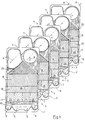
- Fig. 1 shows a schematically exploded view of a plate heat exchanger formed in accordance with the invention and comprising two units of heat transfer plates,
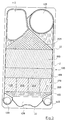
- Fig. 2 shows a schematically front view of a first kind of heat transfer plate, and
- Fig. 3 shows a schematical front view of a second kind of heat transfer plate.
- The plate heat exchanger shown in Fig. 1 comprises two kinds of rectangular, elongated
heat transfer plates flow spaces 3 between them, but as an alternative they could be permanently joined to each other, e.g. through soldering, welding or gluing. - The
heat transfer plates flow spaces 3 crossing and abutting each other to form a number of supporting points between the heat transfer plates. Everysecond flow space 3 forms apassage 4 for evaporation of a fluid, which passage communicates with afluid inlet 5 extending through a lower portion of the heat transfer plates and anoutlet 6 for fluid and generated vapour, which extends through an upper portion of the heat transfer plates. Remaining flow spaces formsecond passages 7 for a heating fluid, which passages communicate with asteam inlet 8 extending through the upper portion of the heat transfer plates, and twocondensate outlets 9 extending through the lower portion of the heat transfer plates. - The heat exchanger shown in Fig. 1 is principally intended for evaporation or concentration of various liquid products by means of climbing film evaporation. The long sides of the
heat transfer plates passages 4 at their lower portion and discharged at their upper portion. - When counterflow heat exchange is preferred the plate heat exchanger is arranged for use as a falling film evaporator with steam as heating medium supplied at the upper portion of the
passages 7 and the condensate produced discharged at the lower portion of thepassages 7. - Each of the
heat transfer plates lower distribution portion 15, aheat transferring portion 16, divided in different horizontally extendedportions upper distribution portion 20. Thelower distribution portion 15 is arranged to convey fluid in eachpassage 4, essentially vertically upwards from theinlet 5 to theheat transfer portion 16, and in eachpassage 7, to convey the condensate both vertically downwards and horizontally towards theoutlets 9. The upper distribution portion is formed in a manner which appears more closely in US 3783090. - The lower horizontally extended
portion 17 is divided into a number ofzones inlet 5 for the fluid in each of theevaporating passages 4. The ridges and grooves in thezones evaporating passage 4, which gradually decreases from one to the other of the vertical sides of the heat transfer plates. By this a desired distribution of the flow of fluid is achieved in theevaporating passages 4 between said vertical sides. - The
heat transfer plates port port 11A and 11B, respectively at the top, for concentrated fluid and generated vapour, aport 12A and 12B, respectively, at the top for heating steam and twoports - The
heat transfer plates lower distribution portions upper distribution portions heat transfer portions 16A and 16B, respectively, which latter are divided in different horizontally extendedportions lower portions zones - The
heat transfer plate 1 has on one of its sides a number ofgrooves 21 in which a unitary gasket is received. The gasket extends around each of theports heat exchange plate 2 has a number ofgrooves 22 accommodating a gasket extending around each of theports heat transfer plates - In the horizontally extended
portions 17A-19A and 17B-19B, respectively, the ridges and the grooves incline differently against the intended main flow direction of the fluid. In particular, the gradient decreases from one zone to another from below and upwards. - Fluid which is to be completely or partly evaporated is supplied into the plate heat exchanger through the
fluid inlet 5 which is located in the lower part of the heat transfer plates, and then flows upwards through thepassage 4. Fluid is evenly distributed across the width of the heat transfer plates between thelower distribution portions heat transfer portions 16A and 16B the fluid first passes theportions zones zones 23A and 23B, located at one vertical side of the plate, have a corrugation pattern providing a relatively great flow resistance in theevaporation passages 4 for upwardly flowing fluid, i.e. the ridges of the plates cross each other with a comparatively large intervening angle directed against the flow direction of the fluid. Thus, the heat transfer between the plates and the fluid becomes relatively efficient and consequently, vapour is generated relatively soon in these portions of thepassages 4. - In the
corrugation zones 23A-26A and 23B-26B, respectively, the ridges and grooves incline differently against the intended main flow direction of the fluid. Thus, the gradient decreases from one zone to another from one to the other vertical side of each plate. In the embodiment of the invention shown in the drawing an angle a of theplate 1 between the main flow direction of the fluid (shown with a vertical dash and dot line) and the direction of the corrugation ridges is -40° in thezone 23A, -36° in thezone 24A, -30° in thezone 25A and -22° in thezone 26A. In theplate 2 an angle β between the flow direction of the fluid and the direction of the corrugating ridges is +40° in the zone 23B, +36° in the zone 24B, +30° in the zone 25B and +22° in thezone 26B. As a result the intermediate angle for the intersecting ridges of theplates zones 23A and B, 72° in thezones 24A and B, 60° in thezones 25A and B and 44° in thezones 26A and B. For theportions portions portions 19A and 19B. The values given for these angles have been chosen with reference to a certain heat exchange task for the present heat exchanger. Other values can of course be chosen for other heat exchange tasks. - From the spaces between the
portions portions portions 19A and 19B, which have gradually decreasing angles between the crossing ridges, i.e. a more and more acute intervening angle is formed by the ridges, with respect to the flow direction. The flow resistance for the fluid and generated vapour thus decreases gradually partly from one vertical side to the other of each plate in the area of theportions portions 17A-19A and 17B-19B. Fluid and generated vapour then continue to theupper distribution areas outlet 6. - In the
passages 7 for the heating medium, the flow is performed in the opposite direction. Steam is thus supplied through the steam inlet 8 (Fig. 1) and in thepassages 7 is subjected to a gradually increasing flow resistance. In Fig. 1 twocondensate outlets 9 are shown, but only one need be used. Owing to the flow resistance between theportions passages 7 is effected. Since the laterally varying flow resistance is limited to the lower parts of thepassages 7, where the main part of the supplied steam has condensed, this will not effect the distribution of steam in the upper parts of thepassages 7 to any essential extent. - In the embodiment of the invention shown in the drawings, both of the
heat transfer plates extended portions portions 17. However, it should be possible to obtain the aimed effect of the invention even if only one heat transfer plate is divided in this way, while the other heat transfer plate had the same corrugation pattern over the entire heat transfer portions. In addition the different portions of theplates 17A-19A, 23A-26A and 17B-19B, 23B-26B, respectively, have been shown located directly opposite to each other, but as an alternative they could be located so that they only partly overlap each other. Also the number of portions and the size of the portions could of course vary.
Claims (3)
- Plate heat exchanger for evaporating a fluid, comprising a package of abutting rectangular and essentially vertically arranged heat transfer plates (1,2) delimiting flow spaces between themselves and provided with corrugation patterns of ridges and grooves, said ridges intersectingly abutting each other in at least a part of each flow space and forming a number of supporting points between adjacent heat transfer plates (1,2), wherein each alternate flow space forms an evaporating passage (4) for said fluid, which evaporating passage has an inlet (5) for fluid at its lower portion and an outlet (6) for fluid and generated vapour at its upper portion near one of the vertical sides of the heat transfer plates, and the remaining flow spaces form passages (7) for a heating fluid, which passages have inlets (8) at their upper portions near the other vertical sides of the heat transfer plates and outlets (9) at their lower portions, characterised in that in each evaporating passage (4), close to its inlet (5) for fluid, at least one heat transfer plate (1) is provided with a plurality of zones (23A-26A) having different corrugation pattern, arranged laterally adjacent to each other across the heat transfer plate between the vertical sides of the heat transfer plate, the ridges and grooves of the heat transfer plates (1,2) in the area of said zones forming different angles against the main flow direction of the fluid in the evaporating passages (4), which angles are chosen in such a way that the ridges and grooves in consequence of their different directions cooperate to provide a flow resistance in each evaporating passage (4), in its main flow direction, which gradually decreases from said one to said other vertical side of the heat transfer plate.
- Plate heat exchanger according to claim 1, characterised in that the corrugation patterns of the heat transfer plates are designed such that the difference in flow resistance from said one to said other vertical sides of the heat transfer plates, caused by the ridges and grooves of the corrugation pattern, are concentrated to the lower part of each evaporating passage (4) in which fluid supplied during operation has not yet been evaporated to any essential extent.
- Plate heat exchanger according to claim 1 or 2, characterised in that at least alternate heat transfer plates (1) have at least three zones arranged adjacent to each other and being provided with different corrugation pattern.
Applications Claiming Priority (3)
| Application Number | Priority Date | Filing Date | Title |
|---|---|---|---|
| SE9001633A SE466171B (en) | 1990-05-08 | 1990-05-08 | PLATTERS WORKS AATMONISONING A PLATHER WAS ASTMINSTERING A DIVISION WAS A DIVISIONALLY DIVISED BY A FAULTY OF A PORTABLE WORTH PREPARING ACHIEVENING, |
| SE9001633 | 1990-05-08 | ||
| PCT/SE1991/000303 WO1991017406A1 (en) | 1990-05-08 | 1991-04-29 | Plate evaporator |
Publications (2)
| Publication Number | Publication Date |
|---|---|
| EP0485555A1 EP0485555A1 (en) | 1992-05-20 |
| EP0485555B1 true EP0485555B1 (en) | 1994-07-06 |
Family
ID=20379402
Family Applications (1)
| Application Number | Title | Priority Date | Filing Date |
|---|---|---|---|
| EP91909728A Expired - Lifetime EP0485555B1 (en) | 1990-05-08 | 1991-04-29 | Plate evaporator |
Country Status (9)
| Country | Link |
|---|---|
| US (1) | US5226474A (en) |
| EP (1) | EP0485555B1 (en) |
| JP (1) | JP2968042B2 (en) |
| BR (1) | BR9105744A (en) |
| DE (1) | DE69102755T2 (en) |
| DK (1) | DK0485555T3 (en) |
| ES (1) | ES2060386T3 (en) |
| SE (1) | SE466171B (en) |
| WO (1) | WO1991017406A1 (en) |
Families Citing this family (42)
| Publication number | Priority date | Publication date | Assignee | Title |
|---|---|---|---|---|
| DE4142177C2 (en) * | 1991-12-20 | 1994-04-28 | Balcke Duerr Ag | Plate heat exchanger |
| SE469669B (en) * | 1992-01-21 | 1993-08-16 | Alfa Laval Thermal Ab | DISTRIBUTION PATTERNS OF PLATFORM TRANSMITTERS |
| SE505225C2 (en) * | 1993-02-19 | 1997-07-21 | Alfa Laval Thermal Ab | Plate heat exchanger and plate for this |
| GB9426208D0 (en) * | 1994-12-23 | 1995-02-22 | British Tech Group Usa | Plate heat exchanger |
| JP3292128B2 (en) * | 1998-02-27 | 2002-06-17 | ダイキン工業株式会社 | Plate heat exchanger |
| US6186223B1 (en) | 1998-08-27 | 2001-02-13 | Zeks Air Drier Corporation | Corrugated folded plate heat exchanger |
| US6244333B1 (en) | 1998-08-27 | 2001-06-12 | Zeks Air Drier Corporation | Corrugated folded plate heat exchanger |
| JP3100371B1 (en) * | 1999-04-28 | 2000-10-16 | 春男 上原 | Evaporator |
| DE10013437C1 (en) | 2000-03-17 | 2001-12-06 | Xcellsis Gmbh | Foil package for an evaporator made of foils |
| SE516416C2 (en) | 2000-05-19 | 2002-01-15 | Alfa Laval Ab | Plate package, heat transfer plate, plate heat exchanger and use of heat transfer plate |
| SE516537C2 (en) | 2000-05-19 | 2002-01-29 | Alfa Laval Ab | Flat pack and plate heat exchanger |
| DE10035939A1 (en) * | 2000-07-21 | 2002-02-07 | Bosch Gmbh Robert | Heat transfer device |
| SE520702C2 (en) * | 2001-12-18 | 2003-08-12 | Alfa Laval Corp Ab | Heat exchanger plate with at least two corrugation areas, plate package and plate heat exchanger |
| SE520703C2 (en) * | 2001-12-18 | 2003-08-12 | Alfa Laval Corp Ab | Heat exchanger plate with corrugated support area, plate package and plate heat exchanger |
| DE10352881A1 (en) * | 2003-11-10 | 2005-06-09 | Behr Gmbh & Co. Kg | Heat exchanger, in particular charge air / coolant radiator |
| DE10352880A1 (en) | 2003-11-10 | 2005-06-09 | Behr Gmbh & Co. Kg | Heat exchanger, in particular charge air / coolant radiator |
| CN1837718A (en) * | 2006-03-09 | 2006-09-27 | 缪志先 | Fin-plate type heat exchanger |
| CA2584955C (en) * | 2006-05-15 | 2014-12-02 | Sulzer Chemtech Ag | A static mixer |
| CN100516758C (en) * | 2007-06-12 | 2009-07-22 | 缪志先 | Strip-free plate-fin heat exchanger |
| SE534306C2 (en) | 2008-06-17 | 2011-07-05 | Alfa Laval Corp Ab | Heat exchanger plate and plate heat exchanger |
| US8844610B2 (en) * | 2008-09-18 | 2014-09-30 | Multistack, LLC | Double inlet heat exchanger |
| SE533067C2 (en) * | 2008-10-03 | 2010-06-22 | Alfa Laval Corp Ab | plate heat exchangers |
| CN102245994B (en) * | 2008-12-17 | 2015-09-23 | 舒瑞普国际股份公司 | The opening of heat exchanger |
| JP5882739B2 (en) * | 2008-12-17 | 2016-03-09 | スウェップ インターナショナル アクティエボラーグ | High pressure port on the peninsula |
| JP5106453B2 (en) * | 2009-03-18 | 2012-12-26 | 三菱電機株式会社 | Plate heat exchanger and refrigeration air conditioner |
| US9557119B2 (en) * | 2009-05-08 | 2017-01-31 | Arvos Inc. | Heat transfer sheet for rotary regenerative heat exchanger |
| NO331474B1 (en) * | 2009-11-13 | 2012-01-09 | Hamworthy Gas Systems As | Installation for gasification of LNG |
| US8826901B2 (en) * | 2010-01-20 | 2014-09-09 | Carrier Corporation | Primary heat exchanger design for condensing gas furnace |
| SE534765C2 (en) * | 2010-04-21 | 2011-12-13 | Alfa Laval Corp Ab | Plate heat exchanger plate and plate heat exchanger |
| DE102010036654A1 (en) | 2010-07-27 | 2012-03-29 | Peter Rehberg | Plate heat exchanger for evaporating a liquid |
| US9644899B2 (en) * | 2011-06-01 | 2017-05-09 | Arvos, Inc. | Heating element undulation patterns |
| US9395125B2 (en) | 2011-09-26 | 2016-07-19 | Trane International Inc. | Water temperature sensor in a brazed plate heat exchanger |
| FR2982016A1 (en) * | 2011-10-28 | 2013-05-03 | Tmw | GRAVITY FLOW LIQUID SPREADING MEDIUM, SPEEDING SYSTEM AND EVAPORATION COLUMN COMPRISING SUCH A SUPPORT |
| CN102728081A (en) * | 2012-07-22 | 2012-10-17 | 甘肃蓝科石化高新装备股份有限公司 | Detachable climbing film plate type evaporator |
| CN104296586A (en) * | 2013-07-15 | 2015-01-21 | 杭州三花研究院有限公司 | Heat exchanger sheet, heat exchanger heat exchange unit and heat exchanger |
| DK2957851T3 (en) * | 2014-06-18 | 2017-08-07 | Alfa Laval Corp Ab | HEAT TRANSFER PLATE AND PLATE HEAT EXCHANGERS THAT INCLUDE SUCH A HEAT TRANSFER PLATE |
| KR101892549B1 (en) * | 2016-04-28 | 2018-08-30 | 한국원자력연구원 | Heat exchanger and nuclear power plant having the same |
| EP3396293A1 (en) * | 2017-04-26 | 2018-10-31 | Alfa Laval Corporate AB | Heat transfer plate and heat exchanger comprising a plurality of such heat transfer plates |
| CN108592665A (en) * | 2018-03-12 | 2018-09-28 | 新乡市特美特热控技术股份有限公司 | Fin plate heat exchanger |
| US11486657B2 (en) * | 2018-07-17 | 2022-11-01 | Tranter, Inc. | Heat exchanger heat transfer plate |
| DK3660437T3 (en) * | 2018-11-29 | 2021-10-18 | Alfa Laval Corp Ab | PLATE HEAT EXCHANGER AND HEAT EXCHANGER PLATE FOR TREATMENT OF A SUPPLY SUCH AS SEA WATER |
| DK3792581T3 (en) * | 2019-09-13 | 2023-04-17 | Alfa Laval Corp Ab | PLATE HEAT EXCHANGER FOR TREATMENT OF A LIQUID SUPPLY |
Family Cites Families (6)
| Publication number | Priority date | Publication date | Assignee | Title |
|---|---|---|---|---|
| US2872165A (en) * | 1954-09-04 | 1959-02-03 | Separator Ab | Plate type heat exchanger |
| GB1339542A (en) * | 1970-03-20 | 1973-12-05 | Apv Co Ltd | Plate heat exchangers |
| SE411952B (en) * | 1978-07-10 | 1980-02-11 | Alfa Laval Ab | HEAT EXCHANGER INCLUDING A MULTIPLE IN A STATUE INSERTED SWITCHING PLATE |
| SE415928B (en) * | 1979-01-17 | 1980-11-10 | Alfa Laval Ab | PLATTVERMEVEXLARE |
| SE458805B (en) * | 1985-06-06 | 1989-05-08 | Reheat Ab | PLATE HEAT EXCHANGER, EVERY PLATE IS DIVIDED IN THE FOUR AREAS WITH SINCE BETWEEN DIFFERENT DIRECTIONS ON THE CORRUGATIONS |
| DD245247A1 (en) * | 1985-12-24 | 1987-04-29 | Kyffhaeuserhuette Maschf | WAERMEUEBERTRAGUNGSPLATTEN |
-
1990
- 1990-05-08 SE SE9001633A patent/SE466171B/en not_active IP Right Cessation
-
1991
- 1991-04-29 JP JP3509219A patent/JP2968042B2/en not_active Expired - Fee Related
- 1991-04-29 EP EP91909728A patent/EP0485555B1/en not_active Expired - Lifetime
- 1991-04-29 DK DK91909728.7T patent/DK0485555T3/en active
- 1991-04-29 BR BR919105744A patent/BR9105744A/en not_active IP Right Cessation
- 1991-04-29 ES ES91909728T patent/ES2060386T3/en not_active Expired - Lifetime
- 1991-04-29 US US07/761,798 patent/US5226474A/en not_active Expired - Lifetime
- 1991-04-29 WO PCT/SE1991/000303 patent/WO1991017406A1/en active IP Right Grant
- 1991-04-29 DE DE69102755T patent/DE69102755T2/en not_active Expired - Fee Related
Also Published As
| Publication number | Publication date |
|---|---|
| BR9105744A (en) | 1992-08-04 |
| JPH04506996A (en) | 1992-12-03 |
| SE9001633L (en) | 1991-11-09 |
| DE69102755T2 (en) | 1994-10-27 |
| JP2968042B2 (en) | 1999-10-25 |
| SE466171B (en) | 1992-01-07 |
| US5226474A (en) | 1993-07-13 |
| DK0485555T3 (en) | 1994-08-01 |
| SE9001633D0 (en) | 1990-05-08 |
| ES2060386T3 (en) | 1994-11-16 |
| DE69102755D1 (en) | 1994-08-11 |
| EP0485555A1 (en) | 1992-05-20 |
| WO1991017406A1 (en) | 1991-11-14 |
Similar Documents
| Publication | Publication Date | Title |
|---|---|---|
| EP0485555B1 (en) | Plate evaporator | |
| JP2968041B2 (en) | Plate evaporator | |
| EP2304369B1 (en) | Heat exchanger | |
| RU2110030C1 (en) | Plate-type heat exchanger for heat exchange between two liquids at different high flow rates | |
| EP0014066A1 (en) | Plate heat exchanger | |
| EP0371122B1 (en) | Plate evaporator | |
| US6032470A (en) | Plate heat exchanger | |
| GB2121525A (en) | Plate evaporator or condenser | |
| WO1983001998A1 (en) | Heat exchanger plate | |
| EP0621940B1 (en) | Distribution pattern of a plate heat exchanger | |
| AU596305B2 (en) | Falling film liquor heater | |
| JP4194938B2 (en) | Heat transfer plate, plate pack and plate heat exchanger | |
| KR102553537B1 (en) | Heat exchanger plates and plate heat exchangers for handling feeds such as seawater | |
| JPH0526588A (en) | Liquid dispersing device for liquid downflow type plate system heat exchanger | |
| JPH0979769A (en) | Heat exchanger with brazing plate and treating method of fluid of two phase in heat exchanger thereof | |
| JPH11287572A (en) | Brazing plate type heat exchanger | |
| JPH10197169A (en) | Dephlegmator |
Legal Events
| Date | Code | Title | Description |
|---|---|---|---|
| PUAI | Public reference made under article 153(3) epc to a published international application that has entered the european phase |
Free format text: ORIGINAL CODE: 0009012 |
|
| 17P | Request for examination filed |
Effective date: 19911220 |
|
| AK | Designated contracting states |
Kind code of ref document: A1 Designated state(s): DE DK ES FR GB IT SE |
|
| 17Q | First examination report despatched |
Effective date: 19930408 |
|
| GRAA | (expected) grant |
Free format text: ORIGINAL CODE: 0009210 |
|
| RAP1 | Party data changed (applicant data changed or rights of an application transferred) |
Owner name: ALFA-LAVAL THERMAL AB |
|
| ITF | It: translation for a ep patent filed |
Owner name: BARZANO' E ZANARDO MILANO S.P.A. |
|
| AK | Designated contracting states |
Kind code of ref document: B1 Designated state(s): DE DK ES FR GB IT SE |
|
| REG | Reference to a national code |
Ref country code: DK Ref legal event code: T3 |
|
| REF | Corresponds to: |
Ref document number: 69102755 Country of ref document: DE Date of ref document: 19940811 |
|
| ET | Fr: translation filed | ||
| REG | Reference to a national code |
Ref country code: ES Ref legal event code: FG2A Ref document number: 2060386 Country of ref document: ES Kind code of ref document: T3 |
|
| EAL | Se: european patent in force in sweden |
Ref document number: 91909728.7 |
|
| PLBE | No opposition filed within time limit |
Free format text: ORIGINAL CODE: 0009261 |
|
| STAA | Information on the status of an ep patent application or granted ep patent |
Free format text: STATUS: NO OPPOSITION FILED WITHIN TIME LIMIT |
|
| 26N | No opposition filed | ||
| REG | Reference to a national code |
Ref country code: FR Ref legal event code: TP |
|
| REG | Reference to a national code |
Ref country code: FR Ref legal event code: GC |
|
| REG | Reference to a national code |
Ref country code: GB Ref legal event code: IF02 |
|
| REG | Reference to a national code |
Ref country code: GB Ref legal event code: 732E |
|
| REG | Reference to a national code |
Ref country code: FR Ref legal event code: RG |
|
| PGFP | Annual fee paid to national office [announced via postgrant information from national office to epo] |
Ref country code: ES Payment date: 20090508 Year of fee payment: 19 Ref country code: DK Payment date: 20090415 Year of fee payment: 19 |
|
| PGFP | Annual fee paid to national office [announced via postgrant information from national office to epo] |
Ref country code: DE Payment date: 20090428 Year of fee payment: 19 Ref country code: IT Payment date: 20090424 Year of fee payment: 19 Ref country code: FR Payment date: 20090417 Year of fee payment: 19 Ref country code: SE Payment date: 20090407 Year of fee payment: 19 |
|
| PGFP | Annual fee paid to national office [announced via postgrant information from national office to epo] |
Ref country code: GB Payment date: 20090429 Year of fee payment: 19 |
|
| EUG | Se: european patent has lapsed | ||
| REG | Reference to a national code |
Ref country code: DK Ref legal event code: EBP |
|
| GBPC | Gb: european patent ceased through non-payment of renewal fee |
Effective date: 20100429 |
|
| REG | Reference to a national code |
Ref country code: FR Ref legal event code: ST Effective date: 20101230 |
|
| PG25 | Lapsed in a contracting state [announced via postgrant information from national office to epo] |
Ref country code: DE Free format text: LAPSE BECAUSE OF NON-PAYMENT OF DUE FEES Effective date: 20101103 |
|
| PG25 | Lapsed in a contracting state [announced via postgrant information from national office to epo] |
Ref country code: GB Free format text: LAPSE BECAUSE OF NON-PAYMENT OF DUE FEES Effective date: 20100429 Ref country code: IT Free format text: LAPSE BECAUSE OF NON-PAYMENT OF DUE FEES Effective date: 20100429 |
|
| PG25 | Lapsed in a contracting state [announced via postgrant information from national office to epo] |
Ref country code: DK Free format text: LAPSE BECAUSE OF NON-PAYMENT OF DUE FEES Effective date: 20100503 |
|
| REG | Reference to a national code |
Ref country code: ES Ref legal event code: FD2A Effective date: 20110708 |
|
| PG25 | Lapsed in a contracting state [announced via postgrant information from national office to epo] |
Ref country code: ES Free format text: LAPSE BECAUSE OF NON-PAYMENT OF DUE FEES Effective date: 20110628 |
|
| PG25 | Lapsed in a contracting state [announced via postgrant information from national office to epo] |
Ref country code: ES Free format text: LAPSE BECAUSE OF NON-PAYMENT OF DUE FEES Effective date: 20100430 |
|
| PG25 | Lapsed in a contracting state [announced via postgrant information from national office to epo] |
Ref country code: FR Free format text: LAPSE BECAUSE OF NON-PAYMENT OF DUE FEES Effective date: 20100430 |
|
| PG25 | Lapsed in a contracting state [announced via postgrant information from national office to epo] |
Ref country code: SE Free format text: LAPSE BECAUSE OF NON-PAYMENT OF DUE FEES Effective date: 20100430 |