EP0485541B1 - Self adjusting mechanism for the adjustment of the length of control cables - Google Patents
Self adjusting mechanism for the adjustment of the length of control cables Download PDFInfo
- Publication number
- EP0485541B1 EP0485541B1 EP91907483A EP91907483A EP0485541B1 EP 0485541 B1 EP0485541 B1 EP 0485541B1 EP 91907483 A EP91907483 A EP 91907483A EP 91907483 A EP91907483 A EP 91907483A EP 0485541 B1 EP0485541 B1 EP 0485541B1
- Authority
- EP
- European Patent Office
- Prior art keywords
- main body
- adjusting stud
- body member
- retaining
- adjusting
- Prior art date
- Legal status (The legal status is an assumption and is not a legal conclusion. Google has not performed a legal analysis and makes no representation as to the accuracy of the status listed.)
- Expired - Lifetime
Links
Images
Classifications
-
- F—MECHANICAL ENGINEERING; LIGHTING; HEATING; WEAPONS; BLASTING
- F16—ENGINEERING ELEMENTS AND UNITS; GENERAL MEASURES FOR PRODUCING AND MAINTAINING EFFECTIVE FUNCTIONING OF MACHINES OR INSTALLATIONS; THERMAL INSULATION IN GENERAL
- F16C—SHAFTS; FLEXIBLE SHAFTS; ELEMENTS OR CRANKSHAFT MECHANISMS; ROTARY BODIES OTHER THAN GEARING ELEMENTS; BEARINGS
- F16C1/00—Flexible shafts; Mechanical means for transmitting movement in a flexible sheathing
- F16C1/10—Means for transmitting linear movement in a flexible sheathing, e.g. "Bowden-mechanisms"
- F16C1/22—Adjusting; Compensating length
- F16C1/226—Adjusting; Compensating length by adjusting the effective length of the sheathing
-
- F—MECHANICAL ENGINEERING; LIGHTING; HEATING; WEAPONS; BLASTING
- F16—ENGINEERING ELEMENTS AND UNITS; GENERAL MEASURES FOR PRODUCING AND MAINTAINING EFFECTIVE FUNCTIONING OF MACHINES OR INSTALLATIONS; THERMAL INSULATION IN GENERAL
- F16C—SHAFTS; FLEXIBLE SHAFTS; ELEMENTS OR CRANKSHAFT MECHANISMS; ROTARY BODIES OTHER THAN GEARING ELEMENTS; BEARINGS
- F16C1/00—Flexible shafts; Mechanical means for transmitting movement in a flexible sheathing
- F16C1/10—Means for transmitting linear movement in a flexible sheathing, e.g. "Bowden-mechanisms"
- F16C1/102—Arrangements to mount end fittings of the sheathings to support walls or brackets
- F16C1/105—Arrangements to mount end fittings of the sheathings to support walls or brackets to a slot in the bracket
-
- F—MECHANICAL ENGINEERING; LIGHTING; HEATING; WEAPONS; BLASTING
- F16—ENGINEERING ELEMENTS AND UNITS; GENERAL MEASURES FOR PRODUCING AND MAINTAINING EFFECTIVE FUNCTIONING OF MACHINES OR INSTALLATIONS; THERMAL INSULATION IN GENERAL
- F16C—SHAFTS; FLEXIBLE SHAFTS; ELEMENTS OR CRANKSHAFT MECHANISMS; ROTARY BODIES OTHER THAN GEARING ELEMENTS; BEARINGS
- F16C1/00—Flexible shafts; Mechanical means for transmitting movement in a flexible sheathing
- F16C1/26—Construction of guiding-sheathings or guiding-tubes
- F16C1/262—End fittings; Attachment thereof to the sheathing or tube
-
- Y—GENERAL TAGGING OF NEW TECHNOLOGICAL DEVELOPMENTS; GENERAL TAGGING OF CROSS-SECTIONAL TECHNOLOGIES SPANNING OVER SEVERAL SECTIONS OF THE IPC; TECHNICAL SUBJECTS COVERED BY FORMER USPC CROSS-REFERENCE ART COLLECTIONS [XRACs] AND DIGESTS
- Y10—TECHNICAL SUBJECTS COVERED BY FORMER USPC
- Y10T—TECHNICAL SUBJECTS COVERED BY FORMER US CLASSIFICATION
- Y10T74/00—Machine element or mechanism
- Y10T74/20—Control lever and linkage systems
- Y10T74/20396—Hand operated
- Y10T74/20402—Flexible transmitter [e.g., Bowden cable]
- Y10T74/2045—Flexible transmitter [e.g., Bowden cable] and sheath support, connector, or anchor
-
- Y—GENERAL TAGGING OF NEW TECHNOLOGICAL DEVELOPMENTS; GENERAL TAGGING OF CROSS-SECTIONAL TECHNOLOGIES SPANNING OVER SEVERAL SECTIONS OF THE IPC; TECHNICAL SUBJECTS COVERED BY FORMER USPC CROSS-REFERENCE ART COLLECTIONS [XRACs] AND DIGESTS
- Y10—TECHNICAL SUBJECTS COVERED BY FORMER USPC
- Y10T—TECHNICAL SUBJECTS COVERED BY FORMER US CLASSIFICATION
- Y10T74/00—Machine element or mechanism
- Y10T74/20—Control lever and linkage systems
- Y10T74/20396—Hand operated
- Y10T74/20402—Flexible transmitter [e.g., Bowden cable]
- Y10T74/20462—Specific cable connector or guide
Landscapes
- Engineering & Computer Science (AREA)
- General Engineering & Computer Science (AREA)
- Health & Medical Sciences (AREA)
- Oral & Maxillofacial Surgery (AREA)
- Mechanical Engineering (AREA)
- Flexible Shafts (AREA)
- Automotive Seat Belt Assembly (AREA)
- Details Of Connecting Devices For Male And Female Coupling (AREA)
- Laying Of Electric Cables Or Lines Outside (AREA)
- Mechanical Control Devices (AREA)
Abstract
Description
- The object of the present invention is a control cable length self-adjusting mechanism which, specifically, is applicable to the adjustment of the length of sheathed steel cables which are regularly used in control and regulation devices and, in particular, to the automobile industry.
- Sheathed steel control cables are widely used in the automobile industry as a means linking devices such as, for example, the clutch pedal and the plate operating lever, or in automatic gear change controls, connecting the gear change lever to the gearbox. To be precise, the control cables are usually delivered from origin for mounting with a small number of operations in the motor vehicle. Such control cables, which are dimensioned and provided at the ends thereof with corresponding connexion terminals adapted to each particular application, incorporate a control cable length self-adjusting device for compensating the variations which arise during the assembly process in each particular vehicle with regard to the theoretical distance between the mechanisms connected by said cable.
- The self-adjusting device performs the function of automatically regulating and setting the optimum length of the control cable during the assembly of the latter in the vehicle, once attached by way of the connexion terminals disposed at the respective ends thereof to the mechanisms it connects, with the said self-adjusting device being anchored to a fixed point of the motor vehicle structure.
- The known embodiments of control cable length self-adjusting devices comprise all or some of the following operative members:
- a main body member through which an adjusting stud may suitably slide. This is provided with a retaining screw thread and is firmly attached at one end thereof to the sheath of the steel cable. The steel cable, unsheathed, may slide longitudinally through the adjusting stud. The main body member is provided with mechanical means allowing it to be anchored to a fixed point of the motor vehicle structure.
- retaining means disposed inside the main body member. These means operate on the adjusting stud so as to set the position thereof relative to the said fixed point.
- and a control spring coaxially disposed relative to the adjusting stud. This spring presses permanently against the main body member and against the adjusting stud at the end thereof attached to the steel cable sheath.
- The above described control cable length self-adjusting devices are supplied from origin with the control spring compressed. Under these conditions, the said devices operate as follows: when the control cable is attached by way of the terminals thereof at both ends to the mechanisms it connects and the main body member is anchored to a fixed point on the vehicle structure, the adjusting stud is released from the retaining means and under the urging of the control spring it establishes the appropriate length of the sheathed steel cable between the adjusting stud and the corresponding mechanism. Thereafter the new position of the adjusting stud relative to the said fixed point is set with the said retaining means, with the control cable length being appropriately set in this way for the appropriate functioning of the mechanisms connected thereby.
- As an embodiment of said control cable length self-adjusting devices, there may be cited Spanish patent P 8803905 for "Control cable tension self-adjusting device" or US-A-4 854 185, which comprise all the operative members succinctly described above.
- Generally speaking, the known embodiments of control cable length self-adjusting devices have all or some of the following drawbacks limiting their operativity:
- (a) they require tools for manipulating the retaining means mounted in the main body member which operate on the adjusting stud during the operations of adjusting and setting the control cable length; and
- (b) the manipulating on the retaining means during the operations of adjusting and setting the control cable length is transversal to the axis defined by the adjusting stud.
- (c) the retaining means are not sufficiently robust or reliable.
- Such limitations cause an increase of the cost of installation of the control cables in all those cases in which the self-adjusting device is located, for needs derived from the design and/or location of the devices connected by the control cable, in points of the motor vehicle structure of difficult and/or limited access which greatly hinder the use of tools under appropriate conditions and/or there is not sufficient space to work transversely on the retaining means operating on the adjusting stud.
- With a view to providing a new embodiment of control cable length self-adjusting device not requiring the use of tools during the control cable length adjusting and setting operations, and so that the retaining means should be operable during said operations longitudinally relative to the axis of the adjusting stud, a control cable length self-adjusting device of new structure is disclosed.
- The control cable length self-adjusting device of the invention is formed by: a main body member snugly housing mechanical retaining means for an adjusting stud passing therethrough and which is provided with means allowing it to be anchored to a fixed point of the motor vehicle structure; the retaining means comprises a notch-like member provided with retaining means, the adjusting stud being formed externally with a retaining screw thread suitably dimensioned relative to the tensile demands made thereon and snugly receiving at one end thereof the corresponding end of a sheath of a steel cable to which it is firmly attached, said steel cable being capable of sliding, unsheathed suitably longitudinally through the adjusting stud and having at said end a perimetral flange against which a control spring presses; the control spring coaxially disposed around the adjusting stud and pressing permanently against the perimetral flange of the adjusting stud, the main body member comprising a centrally disposed extension which extends outwardly over a sufficient distance and the dimensions and external configuration of which allowing said main body member to be anchored to a fixed point of the motor vehicle structure, said extension and main body member being traversed completely by a longitudinal through-hole through which the adjusting stud may snugly slide, said through-hole having an inlet port and defining inside said main body member an elongate recess suitably dimensioned as a seat for the adjusting stud and facing a centrally disposed upper opening;
characterized by the following features: - a) a central part of the main body member is formed as an essentially rectangular and hollow box-like body;
- b) the extension is formed at a first main surface of the body;
- c) on a second main surface opposite to the first the inlet port of the longitudinal through-hole is located; and
- d) on a third and a forth side surface of the body, suitably disposed relative to the through-hole, with corresponding facing apertures of essentially quadrangular perimeter, the respective upper sides of the apertures are traversed by respective channel-like notches;
- e) the retaining means comprises a lever-like prolongation and an actuating extension for acting on the notch-like member to move it toward the retaining screw thread.
- The retaining means for the adjusting stud are formed by:
- a) actuating means, and
- b) an essentially right parallelepipedic retaining spring member suitably dimensioned snugly to slide inside the main body member and which is formed, on one major longitudinal surface thereof, with a centrally disposed transverse notch having a curved perimeter provided with a retaining screw thread dimensioned to mate with the retaining screw thread formed on said adjusting stud, and two suitably dimensioned tabs tangentially angularly disposed to the transverse notch and which may press permanently against the main body member and, on the opposite surface to the former, a transverse positioning notch.
- The said actuating means are formed by:
- a) an actuating shaft, snugly disposed in the main body member transversally to the axis of the centrally disposed extension formed thereon and superimposed on the retaining spring member, and which is formed, at both ends thereof, with corresponding perimetral flanges, which act as dogs to prevent it from coming out of the main body member and, in the portion formed by the width of the transverse positioning notch formed in the retaining spring member, a radial actuating extension which may act on the retaining spring member so that a rotation of said actuating shaft in a sufficient distance longitudinally relative to the axis defined by the adjusting stud causes, in one direction, the retaining spring member to move closer to the adjusting stud, the latter being fixed in position under the combined action of the retaining screw threads formed thereon, while, the rotation of the actuating shaft in the opposite direction causes the retaining spring member to move away from the adjusting stud, thereby releasing it from the combined action of the retaining screw threads formed thereon;
- b) a bent prolongation extending from the actuating shaft for facilitating operation of said shaft; and
- c) a positioning shoulder formed externally on the main body member in functional correspondence with the radial extension extending from the actuating shaft, said positioning shoulder being adapted to set the position of said radial extension in which the position of the adjusting stud is set.
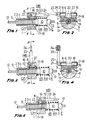
- The control cable length self-adjusting mechanism is represented in the sheet of drawings accompanying the present specification. In the drawings:
- Figure 1 is a cross section view of the mechanism of the invention, the adjusting stud being in the position set at origin.
- Figure 2 is a cross section view on the line II-II of Figure 1.
- Figure 3 is a cross section view of the mechanism of the invention, showing a position occupied by the adjusting stud during the operations of adjusting the length of the sheathed steel cable.
- Figure 4 is a cross section view on the line IV-IV of Figure 3.
- Figure 5 is a cross section view of the mechanism of the invention showing the fixing of the adjusting stud once the control cable length has been adjusted.
- The control cable length self-adjusting mechanism of the invention described as an example of embodiment is constituted, as shown in Figures 1, 3 and 5, of the sheet of drawings, by the main body member CP conveniently housing the adjusting stud VR, and the retaining means MR, and by the control spring RR.
- The main body member CP and the retaining means MR are preferably made from plastics material of appropriate mechanical properties, while the adjusting stud VR is preferably made from metallic materials.
- As shown in all the Figures, the main body member CP is hollow and of essentially right parallelepipedic shape. One of the ends thereof is provided, in this embodiment, with a curved extension 1 for structural reinforcement. The main body member CP is formed on one of the sides thereof with the centrally disposed cylindrical extension 2, shown in Figures 1, 3 and 5, which is formed externally with three perimetral ribs 3. The cylindrical extension 2 and perimetral ribs 3 are for anchoring the main body member CP to a fixed point of the motor vehicle structure which, for greater clarity of illustration, has not been shown in the drawing sheet.
- The main body member CP is provided with the through-hole 4 centrally disposed relative to the longitudinal axis defined by the centrally disposed cylindrical extension 2 so that the adjusting stud VR may slide snugly therethrough as shown in all the Figures.
- The through-hole 4 defines in the main body member CP the
recess 5, shown in detail in Figures 2 and 4, which acts as a seat for the adjusting stud VR. - The main body member CP is also formed with the centrally disposed
upper opening 6, shown in detail in Figures 1, 3 and 5, allowing retaining means MR to slide snugly therethrough during the operations inherent to the mechanism of the invention, of fixing and regulating the control cable length. - The quadrangular openings 7 face each other and are suitably disposed relative to the axis defined by the through-hole 4 of the centrally disposed cylindrical extension 2, as shown in detail in Figures 2 and 4. Said openings 7 are formed, on the sides proximate the surface of the main body member CP facing the surface formed with the
recess 5, as shown in all the Figures, withrespective channels 8. The openings 7 andchannels 8 allow the MR to be snugly housed in the interior of the main body member CP. - The adjusting stud VR is externally formed over a sufficient length with a
retaining screw thread 9, and, at one end thereof, with thehousing 10 and theperimetral flange 11 as shown in detail in Figures 1, 3 and 5. Thehousing 10 is for snugly receiving and firmly fixing the end E of thesheath 12 of thesteel cable 13 and one end of the control spring RR presses permanently against theperimetral flange 11. - The longitudinal through-
bore 14, shown in Figures 2 and 4, of the adjusting stud VR is dimensioned such that thesteel cable 13 may snugly slide therethrough. - The retaining means MR are constituted by the retaining
spring member 15 and by the actuatingshaft 16, both shown in all the Figures. - The retaining
spring member 15 is essentially parallelepipedic and is formed with the transverse notch 17 having the same radius as the adjusting stud VR, said transverse notch being formed with the retaining screw thread 18 which is dimensioned to mate with the retainingscrew thread 9 formed on the adjusting stud VR, as shown in all the Figures. - Figures 2 and 4 show how the retaining
spring member 15 is also formed with the twotabs 19 which are tangentially angularly disposed relative to the transverse notch 17 provided with the retaining screw thread 18 and, on the opposite side, thetransverse positioning notch 20. - The actuating
shaft 16 is provided with twoperimetral flanges 21 which act as retainers and, as shown in Figures 2 and 4, prevent the saidactuating shaft 16 from coming out of the main body member CP when it is located in the main body member CP and superimposed on the retainingspring member 15, as shown in all the Figures. - Figures 1, 2 and 5 show how the actuating
shaft 16 is formed with theradial actuating extension 22, the size of which snugly corresponds to that of thetransverse positioning notch 20 of the retainingspring member 15. The saidradial actuating extension 22 may actuate the retaining spring member is by pressing against it. - In this embodiment, the actuating
shaft 16 is provided with thebent prolongation 23, the free end of which is formed with the widenedportion 24 to facilitate the operations for adjusting and fixing the length of the sheathed steel cable 12-13 for the user. - The main body member CP is formed with the
positioning projection 25, shown in all the Figures and in detail in Figures 2 and 4, for setting the position occupied by thebent prolongation 23 and, consequently, the position of the actuatingshaft 16 once the position of the adjusting stud VR has been set, thereby preventing the adjusting stud VR from extemporaneously being released during the operations prior to assembly of the mechanism of the invention or when it is mounted in the vehicle, with the consequent loss of the previously established adjustment of the length of the sheathed steel cable 12-13. - The control cable length self-adjusting mechanism of the invention works as follows:
- the mechanism is supplied from origin as shown in Figure 1. Under these conditions, the control spring RR is fully compressed and the adjusting stud VR is fixed by the action of the retaining
spring member 15 by way of the respective retainingscrew threads 9 and 18; - once the mechanism of the invention has been mounted at a fixed point of the motor vehicle structure and the respective ends have been attached to the mechanisms connected by the
steel cable 13, not shown in the drawings for the same reasons as stated hereinbefore, a longitudinal rotation of the actuatingshaft 16 by means of thebent prolongation 23 and widenedportion 24 provided therefor, relative to the axis defined by the adjusting stud VR in a sufficient distance, causes, as shown in Figures 3 and 4, the release of the adjusting stud VR from the retaining screw thread 18 of the retainingspring member 15 in view of the action of the twotabs 19, formed on said retainingspring member 15, which press against the corresponding inner surface of the main body member CP separating the saidretaining spring member 15 and adjusting stud VR in a sufficient distance, with the length of the portion of sheathed steel cable 12-13 being adjusted by the action of the control spring RR which presses permanently against the main body member CP and against theperimetral flange 11 of the adjusting stud VR, moving the latter longitudinally in the distance required by each particular application; - once the length of the control cable has been adjusted, the rotation of the actuating
shaft 16 again longitudinally relative to the axis defined by the adjusting stud VR by means of thebent prolongation 23 and widenedportion 24, returning it to the initial position, as shown in Figures 2 and 5, will fix the adjusting stud VR in the new position by means of the retaining screw thread 18 of the retainingspring member 15 since the latter is pressed by theradial actuating extension 22 of the actuatingshaft 16; - and, under these conditions, as under the initial ones previously described, the position occupied by the
bent prolongation 23 of the actuatingshaft 16 is in turn fixed, preventing extemporaneous release with the consequent loss of the control cable length adjustment, by the action of thepositioning projection 25 formed on the main body member CP as shown in detail in Figures 1, 2 and 5.
Claims (3)
- A control cable length self-adjusting device which is formed by: a main body member (CP) snugly housing mechanical retaining means (MR) for an adjusting stud (VR) passing therethrough and which is provided with means (2, 3) allowing it to be anchored to a fixed point of the motor vehicle structure; the retaining means (MR) comprises a notch-like member (17) provided with retaining means (18), the adjusting stud (VR) being formed externally with a retaining screw thread (9) suitably dimensioned relative to the tensile demands made thereon and snugly receiving at one end thereof the corresponding end (E) of a sheath (12) of a steel cable (13) to which it is firmly attached, said steel cable (13) being capable of sliding, unsheathed suitably longitudinally through the adjusting stud (VR) and having at said end a perimetral flange (11) against which a control spring (RR) presses; the control spring (RR) coaxially disposed around the adjusting stud (VR) and pressing permanently against the perimetral flange (11) of the adjusting stud (VR); the main body member (CP) comprising a centrally disposed extension (2) which extends outwardly over a sufficient distance and the dimensions and external configuration of which allowing said main body member (CP) to be anchored to a fixed point of the motor vehicle structure, said extension (2) and main body member (CP) being traversed completely by a longitudinal through-hole (4) through which the adjusting stud (VR) may snugly slide, said through-hole (4) having an inlet port and defining inside said main body member (CP) an elongate recess (5) suitably dimensioned as a seat for the adjusting stud (VR) and facing a centrally disposed upper opening (6);
characterized by the following features:a) a central part of the main body member (CP) is formed as an essentially rectangular and hollow box-like body (CP) ;b) the extension (2) is formed at first main surface of the body (CP) ;c) on a second main surface opposite to the first the inlet port of the longitudinal through-hole (4) is located; andd) on a third and a forth side surface of the body (CP), suitably disposed relative to the through-hole (4), with corresponding facing apertures (7) of essentially quadrangular perimeter, the respective upper sides of the apertures are traversed by respective channel-like notches (8);e) the retaining means (MR) comprises a lever-like prolongation (23) and an actuating extension (22) for acting on the notch-like member (17) to move it toward the retaining screw thread (9). - The control cable length self-adjusting mechanism of claim 1, characterized in that the retaining means (MR) for the adjusting stud (VR) are formed by:a) actuating means (16, 21, 22, 23, 24 and 25); andb) an essentially right parallelepipedic retaining spring member (15) suitably dimensioned snugly to slide inside the main body member (CP) and which is formed, on one major longitudinal surface thereof, with a centrally disposed transverse notch (17) having a curved perimeter provided with a retaining screw thread (18) dimensioned to mate with the retaining screw thread (9) formed on said adjusting stud (VR), and two suitably dimensioned tabs (19) tangentially angularly disposed to the transverse notch (17) and which may press permanently against the main body member (CP) and, on the opposite surface to the former, a transverse positioning notch (20).
- The control cable length self-adjusting mechanism of claims 1 and 2, characterized in that the actuating means are formed by:a) an actuating shaft (16), snugly disposed in the main body member (CP), tranversally to the axis of the centrally disposed extension (2) formed thereon and superimposed on the retaining spring member (15), and which is formed, at both ends thereof, with corresponding perimetral flanges (21), which act as dogs to prevent it from coming out of the main body member (CP) and, in the portion formed by the width of the transverse positioning notch (20) formed in the retaining spring member (15), a radial actuating extension (22) which may act on the retaining spring member (15) so that a rotation of said actuating shaft (16) in a sufficient distance longitudinally relative to the axis defined by the adjusting stud (VR) causes, in one direction, the retaining spring member (15) to move closer to the adjusting stud (VR), the latter being fixed in position under the combined action of the retaining screw threads (9, 18) formed thereon, while, the rotation of the actuating shaft (16) in the opposite direction causes the retaining spring member (15) to move away from the adjusting stud (VR), thereby releasing it from the combined action of the retaining screw threads (9, 18) formed thereon; b) a bent prolongation (23) extending from the actuating shaft (16) for facilitating operation of said shaft; and c) a positioning shoulder (25) formed externally on the main body member (CP) in functional correspondence with the bent prolongation (23) extending from the actuating shaft (16), said positioning shoulder (25) being adapted to set the position of said bent prolongation (23) in which the position of the adjusting stud (VR) is fixed.
Applications Claiming Priority (3)
| Application Number | Priority Date | Filing Date | Title |
|---|---|---|---|
| ES9001506A ES2024819A6 (en) | 1990-05-31 | 1990-05-31 | Self adjusting mechanism for the adjustment of the length of control cables. |
| ES9001506 | 1990-05-31 | ||
| PCT/ES1991/000020 WO1991019110A1 (en) | 1990-05-31 | 1991-04-09 | Self adjusting mechanism for the adjustment of the length of control cables |
Publications (2)
| Publication Number | Publication Date |
|---|---|
| EP0485541A1 EP0485541A1 (en) | 1992-05-20 |
| EP0485541B1 true EP0485541B1 (en) | 1996-03-13 |
Family
ID=8267541
Family Applications (1)
| Application Number | Title | Priority Date | Filing Date |
|---|---|---|---|
| EP91907483A Expired - Lifetime EP0485541B1 (en) | 1990-05-31 | 1991-04-09 | Self adjusting mechanism for the adjustment of the length of control cables |
Country Status (8)
| Country | Link |
|---|---|
| US (1) | US5259265A (en) |
| EP (1) | EP0485541B1 (en) |
| JP (1) | JPH05501910A (en) |
| AT (1) | ATE135446T1 (en) |
| AU (1) | AU7670291A (en) |
| DE (1) | DE69117882T2 (en) |
| ES (1) | ES2024819A6 (en) |
| WO (1) | WO1991019110A1 (en) |
Cited By (2)
| Publication number | Priority date | Publication date | Assignee | Title |
|---|---|---|---|---|
| DE10127630C2 (en) * | 2000-06-13 | 2003-04-30 | Kuester Automotive Control Sys | Device for length adjustment, in particular remote control in motor vehicles |
| DE102014007161A1 (en) * | 2014-05-15 | 2015-11-19 | GM Global Technology Operations LLC (n. d. Gesetzen des Staates Delaware) | Longitudinal adjuster |
Families Citing this family (14)
| Publication number | Priority date | Publication date | Assignee | Title |
|---|---|---|---|---|
| US5142933A (en) * | 1991-05-23 | 1992-09-01 | Teleflex Incorporated | Motion transmitting remote control assembly having conduit length adjuster |
| GB2265956B (en) * | 1992-04-06 | 1995-09-27 | Nhk Spring Co Ltd | An adjustable mounting for a control cable |
| DE4321985C1 (en) * | 1993-07-01 | 1995-01-12 | Ameu Management Corp | Adjustment device in a seat for a pelvic and / or lumbar support arranged in a backrest which can be connected to the seat and having a Bowden cable arrangement connecting it |
| ES2117927B1 (en) * | 1995-02-20 | 1999-04-01 | Fico Cables Sa | SELF-ADJUSTMENT DEVICE FOR CONTROL CABLES. |
| ES2128233B1 (en) * | 1996-03-15 | 2000-02-01 | Fico Cables Sa | SELF-ADJUSTING DEVICE FOR CONTROL CABLE TERMINALS. |
| US5842552A (en) * | 1996-12-26 | 1998-12-01 | White Consolidated Industries, Inc. | Self-adjusting drive-control cable for a lawn mower |
| FR2767566B1 (en) * | 1997-08-19 | 1999-11-26 | Peugeot | CONTROL ARRANGEMENT WITH SHEATHED CABLE, PARTICULARLY FOR ACTUATING A FRICTION CLUTCH OF A MOTOR VEHICLE |
| US6053064A (en) * | 1998-05-01 | 2000-04-25 | L & P Property Management Company | Lumbar support screw actuator |
| DE10055425C2 (en) * | 2000-11-09 | 2002-11-21 | Faurecia Autositze Gmbh & Co | Device for length compensation on Bowden cables |
| WO2007056650A2 (en) * | 2005-11-02 | 2007-05-18 | L & P Property Management Company | Hinged slide and snap cable end fitting |
| DE202008016381U1 (en) | 2008-12-11 | 2010-04-29 | Al-Ko Kober Ag | cable setting |
| US8690109B2 (en) | 2011-08-03 | 2014-04-08 | Haworth, Inc. | Automatic gap adjustor |
| US8850921B2 (en) | 2011-12-12 | 2014-10-07 | Chrysler Group Llc | Cable-length-adjustment device |
| DE102012201709B4 (en) * | 2012-02-06 | 2015-06-25 | Johnson Controls Gmbh | Device for reversing the direction of movement and / or actuation of a control cable of a mechanism |
Family Cites Families (15)
| Publication number | Priority date | Publication date | Assignee | Title |
|---|---|---|---|---|
| US3572159A (en) * | 1969-06-12 | 1971-03-23 | Teleflex Inc | Motion transmitting remote control assembly |
| GB1366325A (en) * | 1970-10-08 | 1974-09-11 | Teleflex Inc | Remote control assembly |
| US3710645A (en) * | 1970-10-08 | 1973-01-16 | Teleflex Inc | Remote control assembly |
| US4294133A (en) * | 1979-09-24 | 1981-10-13 | Ford Motor Company | Bowden cable retainer and adjuster |
| US4669330A (en) * | 1984-10-01 | 1987-06-02 | Ford Motor Company | Cable length adjuster |
| US4841806A (en) * | 1985-09-13 | 1989-06-27 | Teleflex Incorporated | Self-adjust mini increment |
| US4676119A (en) * | 1985-09-13 | 1987-06-30 | Teleflex Incorporated | Remote control levered self adjust actuator |
| US4694706A (en) * | 1986-02-14 | 1987-09-22 | Acco Babcock Inc. | Control cable conduit length adjustment device |
| JPS62209210A (en) * | 1986-03-07 | 1987-09-14 | Nippon Cable Syst Inc | Tension adjusting device for operating wire |
| US4688445A (en) * | 1986-04-21 | 1987-08-25 | Teleflex Incorporated | Remote control balanced adjust system |
| GB2195161A (en) * | 1986-09-12 | 1988-03-30 | Ford Motor Co | Cable clip |
| US4872367A (en) * | 1988-06-17 | 1989-10-10 | Teleflex Incorporated | Lost motion end fitting |
| JPH0262415A (en) * | 1988-08-24 | 1990-03-02 | Nippon Cable Syst Inc | Adjusting device for control cable installation position |
| US4854185A (en) * | 1988-10-17 | 1989-08-08 | Babcock Industries Inc. | Manually operated and locked conduit length adjuster system |
| ES2024240A6 (en) * | 1990-05-07 | 1992-02-16 | Pujol & Tarago | Self-adjustment device for adjusting the length of control cables. |
-
1990
- 1990-05-31 ES ES9001506A patent/ES2024819A6/en not_active Expired - Lifetime
-
1991
- 1991-04-09 AT AT91907483T patent/ATE135446T1/en not_active IP Right Cessation
- 1991-04-09 WO PCT/ES1991/000020 patent/WO1991019110A1/en active IP Right Grant
- 1991-04-09 EP EP91907483A patent/EP0485541B1/en not_active Expired - Lifetime
- 1991-04-09 AU AU76702/91A patent/AU7670291A/en not_active Abandoned
- 1991-04-09 US US07/828,928 patent/US5259265A/en not_active Expired - Fee Related
- 1991-04-09 JP JP3506894A patent/JPH05501910A/en active Pending
- 1991-04-09 DE DE69117882T patent/DE69117882T2/en not_active Expired - Fee Related
Cited By (2)
| Publication number | Priority date | Publication date | Assignee | Title |
|---|---|---|---|---|
| DE10127630C2 (en) * | 2000-06-13 | 2003-04-30 | Kuester Automotive Control Sys | Device for length adjustment, in particular remote control in motor vehicles |
| DE102014007161A1 (en) * | 2014-05-15 | 2015-11-19 | GM Global Technology Operations LLC (n. d. Gesetzen des Staates Delaware) | Longitudinal adjuster |
Also Published As
| Publication number | Publication date |
|---|---|
| AU7670291A (en) | 1991-12-31 |
| ATE135446T1 (en) | 1996-03-15 |
| US5259265A (en) | 1993-11-09 |
| ES2024819A6 (en) | 1992-03-01 |
| DE69117882T2 (en) | 1996-07-25 |
| JPH05501910A (en) | 1993-04-08 |
| DE69117882D1 (en) | 1996-04-18 |
| EP0485541A1 (en) | 1992-05-20 |
| WO1991019110A1 (en) | 1991-12-12 |
Similar Documents
| Publication | Publication Date | Title |
|---|---|---|
| EP0485541B1 (en) | Self adjusting mechanism for the adjustment of the length of control cables | |
| EP0431307B1 (en) | Adjustable cable sheath terminal | |
| US4378713A (en) | Self-adjusting cable control device | |
| EP0365242B1 (en) | Manually-operable and lockable length adjuster | |
| US4344518A (en) | Self-adjusting cable conduit mechanism | |
| CA2141844C (en) | Rotary temperature control device | |
| US5235867A (en) | Lockout means for cable tension adjustment | |
| EP0699841B1 (en) | Control system with bowden wire assembly | |
| EP0485540B1 (en) | Self-adjustment device for adjusting the length of control cables | |
| EP0619437B1 (en) | Device for self-ajusting the length of control cables | |
| US5142933A (en) | Motion transmitting remote control assembly having conduit length adjuster | |
| JPS63195034A (en) | Control cable mounting device | |
| EP1568539A1 (en) | Actuation mechanism for bowden cables | |
| US4261221A (en) | Control cable positioning device | |
| GB2176861A (en) | Device for automatically regulating tension applied to inner wire of control cable for slack adjustment | |
| US4292858A (en) | Brake cable operating means of the overcenter toggle type | |
| EP0260980A2 (en) | Constant tension, self-adjusting, cable control device | |
| US4549709A (en) | Device for attaching to a wall the end of a sheath in which a control cable is slidably received | |
| EP0085566B1 (en) | Positioning reel | |
| US4353265A (en) | Brake cable operating apparatus including anchor plate spacer | |
| GB2047519A (en) | Mounting device | |
| EP0690199B1 (en) | Cordlock | |
| US5438890A (en) | Cable position adjusting structure | |
| EP1920163A1 (en) | Adjustment device for a control cable | |
| ES8606592A1 (en) | Automatic adjusting brake actuator. |
Legal Events
| Date | Code | Title | Description |
|---|---|---|---|
| PUAI | Public reference made under article 153(3) epc to a published international application that has entered the european phase |
Free format text: ORIGINAL CODE: 0009012 |
|
| 17P | Request for examination filed |
Effective date: 19920121 |
|
| AK | Designated contracting states |
Kind code of ref document: A1 Designated state(s): AT BE DE FR GB IT NL SE |
|
| 17Q | First examination report despatched |
Effective date: 19930701 |
|
| RAP1 | Party data changed (applicant data changed or rights of an application transferred) |
Owner name: FICO-CABLES, S.A. |
|
| GRAH | Despatch of communication of intention to grant a patent |
Free format text: ORIGINAL CODE: EPIDOS IGRA |
|
| GRAA | (expected) grant |
Free format text: ORIGINAL CODE: 0009210 |
|
| AK | Designated contracting states |
Kind code of ref document: B1 Designated state(s): AT BE DE FR GB IT NL SE |
|
| PG25 | Lapsed in a contracting state [announced via postgrant information from national office to epo] |
Ref country code: NL Free format text: LAPSE BECAUSE OF FAILURE TO SUBMIT A TRANSLATION OF THE DESCRIPTION OR TO PAY THE FEE WITHIN THE PRESCRIBED TIME-LIMIT Effective date: 19960313 Ref country code: BE Effective date: 19960313 Ref country code: AT Effective date: 19960313 |
|
| REF | Corresponds to: |
Ref document number: 135446 Country of ref document: AT Date of ref document: 19960315 Kind code of ref document: T |
|
| REF | Corresponds to: |
Ref document number: 69117882 Country of ref document: DE Date of ref document: 19960418 |
|
| ET | Fr: translation filed | ||
| ITF | It: translation for a ep patent filed |
Owner name: ING. BETTELLO LUIGI |
|
| PG25 | Lapsed in a contracting state [announced via postgrant information from national office to epo] |
Ref country code: SE Effective date: 19960613 |
|
| NLV1 | Nl: lapsed or annulled due to failure to fulfill the requirements of art. 29p and 29m of the patents act | ||
| PLBE | No opposition filed within time limit |
Free format text: ORIGINAL CODE: 0009261 |
|
| STAA | Information on the status of an ep patent application or granted ep patent |
Free format text: STATUS: NO OPPOSITION FILED WITHIN TIME LIMIT |
|
| 26N | No opposition filed | ||
| REG | Reference to a national code |
Ref country code: GB Ref legal event code: IF02 |
|
| PGFP | Annual fee paid to national office [announced via postgrant information from national office to epo] |
Ref country code: GB Payment date: 20040206 Year of fee payment: 14 |
|
| PGFP | Annual fee paid to national office [announced via postgrant information from national office to epo] |
Ref country code: FR Payment date: 20040210 Year of fee payment: 14 |
|
| PGFP | Annual fee paid to national office [announced via postgrant information from national office to epo] |
Ref country code: DE Payment date: 20040528 Year of fee payment: 14 |
|
| PG25 | Lapsed in a contracting state [announced via postgrant information from national office to epo] |
Ref country code: IT Free format text: LAPSE BECAUSE OF NON-PAYMENT OF DUE FEES;WARNING: LAPSES OF ITALIAN PATENTS WITH EFFECTIVE DATE BEFORE 2007 MAY HAVE OCCURRED AT ANY TIME BEFORE 2007. THE CORRECT EFFECTIVE DATE MAY BE DIFFERENT FROM THE ONE RECORDED. Effective date: 20050409 Ref country code: GB Free format text: LAPSE BECAUSE OF NON-PAYMENT OF DUE FEES Effective date: 20050409 |
|
| PG25 | Lapsed in a contracting state [announced via postgrant information from national office to epo] |
Ref country code: DE Free format text: LAPSE BECAUSE OF NON-PAYMENT OF DUE FEES Effective date: 20051101 |
|
| GBPC | Gb: european patent ceased through non-payment of renewal fee |
Effective date: 20050409 |
|
| PG25 | Lapsed in a contracting state [announced via postgrant information from national office to epo] |
Ref country code: FR Free format text: LAPSE BECAUSE OF NON-PAYMENT OF DUE FEES Effective date: 20051230 |
|
| REG | Reference to a national code |
Ref country code: FR Ref legal event code: ST Effective date: 20051230 |