EP1568539A1 - Actuation mechanism for bowden cables - Google Patents
Actuation mechanism for bowden cables Download PDFInfo
- Publication number
- EP1568539A1 EP1568539A1 EP05003331A EP05003331A EP1568539A1 EP 1568539 A1 EP1568539 A1 EP 1568539A1 EP 05003331 A EP05003331 A EP 05003331A EP 05003331 A EP05003331 A EP 05003331A EP 1568539 A1 EP1568539 A1 EP 1568539A1
- Authority
- EP
- European Patent Office
- Prior art keywords
- actuating mechanism
- spring clutch
- shaft
- housing
- spool
- Prior art date
- Legal status (The legal status is an assumption and is not a legal conclusion. Google has not performed a legal analysis and makes no representation as to the accuracy of the status listed.)
- Withdrawn
Links
Images


Classifications
-
- G—PHYSICS
- G05—CONTROLLING; REGULATING
- G05G—CONTROL DEVICES OR SYSTEMS INSOFAR AS CHARACTERISED BY MECHANICAL FEATURES ONLY
- G05G1/00—Controlling members, e.g. knobs or handles; Assemblies or arrangements thereof; Indicating position of controlling members
- G05G1/08—Controlling members for hand actuation by rotary movement, e.g. hand wheels
- G05G1/10—Details, e.g. of discs, knobs, wheels or handles
- G05G1/12—Means for securing the members on rotatable spindles or the like
-
- F—MECHANICAL ENGINEERING; LIGHTING; HEATING; WEAPONS; BLASTING
- F16—ENGINEERING ELEMENTS AND UNITS; GENERAL MEASURES FOR PRODUCING AND MAINTAINING EFFECTIVE FUNCTIONING OF MACHINES OR INSTALLATIONS; THERMAL INSULATION IN GENERAL
- F16C—SHAFTS; FLEXIBLE SHAFTS; ELEMENTS OR CRANKSHAFT MECHANISMS; ROTARY BODIES OTHER THAN GEARING ELEMENTS; BEARINGS
- F16C1/00—Flexible shafts; Mechanical means for transmitting movement in a flexible sheathing
- F16C1/10—Means for transmitting linear movement in a flexible sheathing, e.g. "Bowden-mechanisms"
- F16C1/12—Arrangements for transmitting movement to or from the flexible member
- F16C1/18—Arrangements for transmitting movement to or from the flexible member in which the end portion of the flexible member is laid along a curved surface of a pivoted member
-
- G—PHYSICS
- G05—CONTROLLING; REGULATING
- G05G—CONTROL DEVICES OR SYSTEMS INSOFAR AS CHARACTERISED BY MECHANICAL FEATURES ONLY
- G05G5/00—Means for preventing, limiting or returning the movements of parts of a control mechanism, e.g. locking controlling member
- G05G5/12—Means for preventing, limiting or returning the movements of parts of a control mechanism, e.g. locking controlling member for holding members in an indefinite number of positions, e.g. by a toothed quadrant
Definitions
- This invention relates to an actuating mechanism for the actuation of at least one Bowden cable.
- theses actuation mechanisms are used in the automotive field and herein for example for the actuation of a lumbar support in a motor vehicle seat.
- an actuation mechanism For the introduction of a force onto a Bowden cable, an actuation mechanism is needed.
- This can be an electrical actuation mechanism wherein by means of an electric motor the inner cables of a Bowden cable are tightened or released with respect of the sheath of the Bowden cable via an appropriate mechanism.
- there are manual actuating mechanisms wherein the user actuates a lever or a rotating knob so that the cables of the Bowden cable are tightened or released.
- a manually actuatable actuation mechanism is known from the US patent number 6,334,651 B1 which comprises a one-way clutch which blocks in one direction.
- the actuating mechanism is provided with a lever or a rotating knob and the one-way clutch ensures that the pulling force onto the cable of the Bowden cable is maintained if the lever or the rotating knob is released.
- the one-way clutch is realized by a roll clutch.
- an actuating mechanism for the backrest of a vehicle seat which comprises an elastic element, which returns the lever after the actuation to a rest position.
- the actuating mechanism is further provided with a clutch, which clutches in during an actuation of the hand lever and rotates the element, which is connected to the cable of the Bowden cable. After the actuation, the hand lever is again returned to its rest position, wherein the cable of the Bowden cable remains tightened.
- the shown actuating mechanism comprises a drum, onto which the inner cable of the Bowden cable can be wound. Further, it comprises a fixed housing into which the drum is rotatably mounted and a second housing, which can be rotated by a hand lever. The rotation of the hand lever forces a rotation of the second housing, wherein according to the rotation direction one of two spring clutches are actuated which transmit the rotation of the second housing to a spool. A back rotation of the spool is prevented by a third spring clutch, which is provided as a one-way clutch. For a back rotation of the spool, a force has to be applied via the hand lever, which is higher than the holding force of the one-way clutch.
- a further problem of this invention is to provide an actuating mechanism which is particularly robust and maintenance-free due to its construction. Further, it is desirable that its assembly can be done possibly easy.
- the actuating mechanism according to the invention is thereby blocked in both rotational directions if it is not actuated.
- a pressure as also a pulling force can be transmitted via the cable of the Bowden cable and on the other hand the actuating mechanism can perform an actuation in both rotational directions.
- the second spring clutch supports the first spring clutch during its blocking action by blocking in the direction of the comparable higher pulling force.
- the second spring clutch additionally creates a rotational biasing force, additional to its blocking action, to prevent a mechanical free-play in the actuating mechanism.
- the manual actuation motions are transmitted directly to the cable of the Bowden cable. An undesired free-play between the hand lever and the spool and therefore of the cables of the Bowden cable is eliminated.
- the first spring clutch is biased against the inner surface of the housing.
- the outer side of the first spring clutch thereby contains in its rest condition the inner surface of the housing and can only be difficulty or not at all be rotated due to the frictional effect.
- the first spring clutch is in its rest condition, that means unactuated, in its blocking condition.
- the second spring clutch is biased against the outer surface of the housing.
- the inner side of the second spring clutch contacts in its rest position the outer surface of the housing and can only be difficultly or not at all rotated due to the frictional effect.
- the second spring clutch is in its rest condition, that means unactuated, in its blocking condition.
- the actuating mechanism further comprises a shaft, which is rotatably supported in the housing, which can actuate either a first or a second end of the first spring clutch, to contract the first spring clutch and to release the blocking of the first spring clutch with the housing.
- the shaft can directly or indirectly actuate either a first or a second end of the second spring clutch, to extend the second spring clutch and to release the blocking of the second spring clutch with the housing.
- the shaft comprises at one end a shaft connection, wherein an external rotational motion can be introduced via this shaft connection, to drive the actuating mechanism.
- the shaft connection transmits a rotational motion of a control element to the shaft.
- the control element may for example be a hand lever or a rotating knob, but there are also motoric-driven control elements thinkable which can drive the shaft.
- the spool further comprises an eccentric projection, which projects in axial direction from the spool in the direction of the shaft. Via this axial projection, the spool is engaged and rotated by the shaft.
- the eccentric projection is formed by a sprocket plate, which is additionally mounted at the spool.
- This sprocket plate can be made from another material as the one of the spool.
- the spool can be made from a plastic material and the sprocket plate, which is subjected to higher loads, could be made of a metal.
- the shaft comprises a first actuation face to engage the eccentric projection during a rotation of the shaft in tightening direction T and to transmit a rotational motion in tightening direction T to the spool.
- the shaft can preferably comprise a second actuation face to engage the eccentric projection during a rotation of the shaft in release direction R and to transmit a rotational motion in release direction R to the spool.
- the first end of the second spring clutch is connected to the eccentric projection and the second end of the second spring clutch engages the second actuation face of the shaft, to apply a rotational biasing force between the eccentric projection and the shaft.
- a free play between spool and shaft is prevented.
- the housing comprises two differently arranged connection openings which each can receive the outer sheath of the at least one Bowden cable, to arbitrarily choose the tightening direction of the actuating mechanism.
- the same actuating mechanism for example as well as for the actuation from the left side of a backrest of a seat as well as from the right side of a backrest of a seat.
- the second spring clutch can be inserted in two different orientations into the actuating mechanism to arbitrarily choose the tightening direction of the actuating mechanism.
- the actuating mechanism which is shown in fig. 1 is preferably used for the actuation of a lumbar support (not shown) of a vehicle seat.
- the actuating mechanism 1 is provided with a lever 10, which is manually actuated by the passenger of the vehicle to adjust the lumbar support.
- the actuating mechanism 1 is used to transform the rotational motions which are applied by the passenger into translational motions which are transmitted to the lumbar support via two Bowden cables 90.
- the actuating mechanism 1 can of course also be used for the actuation of other elements, for example the heating, the head rest, the mirrors, or the like.
- Fig. 1 shows an actuating mechanism 1 in assembled condition.
- the actuating mechanism 1 is manually actuated via a lever 10.
- the lever 10 comprises a handle 12 and an essentially cylindrical receptacle 14.
- a rotatable knob or a similar actuator can be provided for manual actuation.
- the actuating mechanism 1 is driven electro-motoric (not shown).
- the lever 10 is rotatably connected to the shaft 20.
- the shaft 20 comprises at one end a shaft connection 28, which positively mates with the inner side of the receptacle 14.
- the shaft 20 transmits a rotational motion of the lever 10 to the inner elements of the actuating mechanism 1.
- These inner elements of the actuating mechanism 1 are enclosed by a housing 70, which is closed by a cover 80 at the front side which opposites the shaft 20.
- the cover 80 is connected by means of unitarily formed clips 82, which engage lugs 74 at the housing 70.
- the housing 70 comprises snap elements 72 at the front side which is directed to the lever 10, by means of which the complete actuating mechanism 1 can be fixed at the metal frame of a vehicle seat (not shown).
- the mounting is done by a simple insertion of the actuating mechanism 1 into the metal frame, wherein the snap elements 72 latch within holes of the metal frame (not shown).
- Fig. 2 shows an essentially cylindrical housing 70, which comprises an opening for the passage of the shaft 20 at one front side. The other front side of the hollow cylindrical housing 70 is completely open. At the outer side of the housing 70, the already discussed lugs 74 are formed, in which the clips 82 of the cover 80 latch after the assembly thereof.
- Fig. 2 further shows an essentially rotational symmetric shaft 20 which comprises at one end a shaft connection 28, which is provided in this embodiment as a squared connection.
- an essentially rotational symmetric engaging body 28 is provided, wherein a segment of a circle is cut out, to provide a first actuation face 22 and a second actuation face 23.
- the function of the engaging body 21 is disclosed in detail below.
- fig. 2 shows an essentially cylindrical spool 40 which comprises two radially revolving cable slots 42 for receiving the inner cables 92 of the Bowden cable 90 and a receptacle hole 44 for receiving the cable ends 94 of the cables 92 of the Bowden cable 90.
- the spool 40 is used to wind or to unwind the cables 92 of the Bowden cable 90, so that the Bowden cable 90 is tightened or released.
- the spool 40 is rotational fixed with a sprocket plate 30, which comprises an axially angled upper portion, which forms an eccentrical projection and which projects in axial direction from the spool 40 in direction of the shaft 20.
- the spool 40 is engaged and rotated via the sprocket plate 30 by the engaging body 21 of shaft 20.
- Fig. 2 further shows a first spring clutch 60 which prevents an undesired rotation of the spool 40. Further a second spring clutch 50 is provided which supports the function of the spring clutch 60 and simultaneously acts for a free-play free function of the actuating mechanism 1.
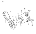
- the arrangement of the separate inner components of the actuating mechanism 1 is shown in fig. 3.
- the housing 70 was removed for clarification.
- Fig. 3 shows that the cable ends 94 are anchored in the receptacle hole 44 of spool 40.
- the cables 92 of the Bowden cables 90 then run in the annular cable slots 42 and can be wound or unwound within them.
- the cable sheaths 96 of the Bowden cables 90 rest against the housing 70.
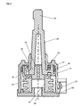
- the spool 40 is rotatably arranged within the housing 70, wherein it is axially rotatably guided by an axial pin 84 at the housing cover 80, which is shown in fig. 5.
- the spool 40 comprises an axial hole 46 wherein the axial pin 84 of the cover 80 engages and thereby provides a friction bearing.
- a sprocket plate 30 is rotatably fixed mounted.
- the sprocket plate 30 forms an eccentric projection which axially projects in direction of shaft 20.
- the sprocket plate 30 in general comprises an L-shaped section. Its eccentric projection further comprises a central recess 32 and lateral actuation faces 34 and 36 which actuate the spring clutches 50, 60.
- an actuation of the spool 40 is done by engaging and moving the sprocket plate 30 at its respective actuation faces 34 and 36 by the engaging body 21 of shaft 20. If the cables 92 of Bowden cables 90 should be tightened in the embodiment of fig. 3, the spool 40 must move in tightening direction T.
- the second spring clutch 50 is arranged axially onto the shaft 20 at the level of its engaging body 21.
- the first spring end 52 of the second spring clutch 50 is arranged within the recess 32 of the sprocket plate 30 and the second spring end 54 of the second spring clutch 50 rests against the second actuation face 23 of shaft 20.
- the first engaging face 34 of sprocket plate 30 is biased against the first actuation face 22 of shaft 20. If now again shaft 20 is rotated in tightening direction T, there is no free-play between the first engaging face 34 and the first actuation face 22, so that spool 40 directly rotates together with shaft 20 in tightening direction T.
- the sprocket plate 30 is taken along by the shaft 20.
- tear forces are transmitted via the cables 92 of Bowden cables 90 so that a rotation in releasing direction R of spool 40 already starts until the spring clutch 50 is rotated by engaging body 21.
- the function of the first spring clutch 60 and the second spring clutch 50 is discussed, which are separately shown in fig. 4.
- the second spring clutch 50 at first acts for biasing the sprocket plate 30 against the engaging body 21 without free-play.
- the spring clutch 50 also fulfils the task to prevent an undesired rotation of spool 40 in release direction R.
- the spring clutch 50 engages in its blocked condition a cylindrical outer face 78 of housing 70 with its inner face 56.
- the cylindrical outer face 78 of housing 70 is located within the housing 70 and it is like the same stationary with respect to the rotating inner elements of actuating mechanism 1.
- the second spring clutch 50 is biased against the outer surface 78 of housing 70.
- the second spring clutch 50 cannot rotate onto the outer surface 78 in its unactuated condition. That means, it is in its blocking condition.
- the blocking of spring clutch 50 can be released by pushing the first spring end 52 in tightening direction T or the second spring end 54 in releasing direction R.
- the diameter of spring clutch 50 increases, so that it can glide over the cylindrical outer face 78 of housing 70. If the first spring end 52 is pushed in releasing direction R or the second spring end 54 in tightening direction T, the diameter of spring clutch 50 decreases and the blocking action is increased.
- the first spring clutch 60 acts also for the preventing of an undesired rotation of spool 40.
- An outer face 66 of spring clutch 60 contacts a cylindrical inner face 76 of housing 70.
- the first spring clutch 60 is preferably biased against the cylindrical inner face 76 of housing 70. In this blocking condition, the spring clutch 60 cannot be rotated within housing 70.
- the spring clutch 60 comprises a first spring end 62 and a second spring end 64. If the first spring end 62 is pushed in tightening direction T or the second spring end 64 is pushed in releasing direction R, the diameter of spring clutch 60 decreases and it can be rotated within housing 70 onto the cylindrical inner face 74.
- first actuating face 22 engages the first spring end 62 of first spring clutch 60, wherein its diameter decreases and it can glide within housing 70.
- second actuating face 23 engages the second spring end 64, whereby again the diameter of spring clutch 60 is decreased and it can be rotated within the housing 70. Thereby, the blocking action of the first spring clutch 60 is released during an actuation of the actuating mechanism 1 by the user via a hand lever 10 or a rotating knob.
- the pretensioning of the first spring clutch 60 must be greater than the force which is transmitted by the spring clutch 50 onto shaft 20 due to the rotation of spool 40.
- the spring constant of the second spring clutch 50 should be smaller than the spring constant of the first spring clutch 60.
- the arrangement of the actuating mechanism 1 according to the invention ensures a reliable blocking of the cables 92 of the Bowden cables 90 in both rotational directions with respect to an undesired rotation. Therefore, the actuating mechanism 1 is preferably designed so that very high pulling loads onto the Bowden cables 90 are securely held by the actuating mechanism 1.
- a particular advantage of the actuating mechanism 1 lies therein, that it is designed as well as for a left-sided as also for a right-sided mounting, for example at the left or the right side of a backrest of a vehicle seat. That means, that the tightening or releasing direction of the actuating mechanism 1 can easily be changed.
- the cables 92 of Bowden cables 90 are guided to the front from the drawing level in the slots 42 of spool 40.
- the tightening direction T is that direction wherein a tension can be applied to the cables 92.
- this is shown by the arrow T, which is directed to the top and which should symbolize a clockwise rotation of the spool 40.
- spool 40 is symmetrically constructed so that cables 92 can also be guided around the other side.
- the Bowden cables 90 exit the housing 70 in a tangential manner. To reverse the rotational directions, the housing 70 must comprise two different connection openings 71, 72, like they are shown in fig. 8.
- the first connection opening 71 of housing 70 is designed in that way, that the sheath 96 of Bowden cables 90 can be received for the case shown in fig. 3. If the rotational direction of actuating mechanism 1 is reversed, the cables 92 on spool 40 run in the opposite direction and the cable sheath 96 is received by the second connecting opening 72 of housing 70.
- the second spring clutch 50 is positioned onto shaft 20, so that its second spring end 54 shows in direction of the first actuation face 22. That means that the second spring clutch 50 is positioned in a mirrored fashion compared to the arrangement shown in fig. 3.
- the first spring end 52 of spring clutch 50 is again arranged within the recess 32 of sprocket plate 30.
- the single components of the actuating mechanism 1 are axially rotatable nested into each other. Thereby, the requirement of providing an additional rotational axis does not apply.
- spool 40 is guided by a pin 84 in housing cover 80.
- shaft 20 is guided by a pin 46 of spool 40, which engages into a hole 26 of shaft 20. Further, shaft 20 is supported within a support hole within housing 70.
- An assembly of the actuating mechanism 1 can therefore very easily be done by a simple nesting of the single components. This arrangement is fixed by latching the housing cover 80 at the housing 70.
- the actuating mechanism 1 is very robust and therefore constructed for low maintenance due to this arrangement of the single components.
- the shaft 20, the spool 40, the housing 70 and the housing cover 80 are preferably produced of a plastic material. Preferably glass-fiber reinforced plastic material is used.
- the sprocket plate 30 consists preferably also of a plastic material or a sheet metal.
- the first spring clutch 60 and the second spring clutch 50 are preferably produced of a spring steel.
Abstract
Description
- Fig. 1
- the actuating mechanism according to the invention in a three-dimensional view in assembled condition;
- Fig. 2
- the actuating mechanism according to the invention shown in a three-dimensional explosional view;
- Fig. 3
- the inner components of the actuating mechanism according to the invention shown in a three-dimensional view, wherein the housing is removed;
- Fig. 4
- an elevational view onto the two spring clutches of the actuating mechanism according to the invention;
- Fig. 5
- a sectional view through the actuating mechanism according to the invention in a longitudinal sectional view through the center line;
- Fig. 6
- an axial elevational view onto the actuating mechanism according to the invention during an actuation in tightening direction T, wherein the housing is removed;
- Fig. 7
- an axial elevational view onto the actuating mechanism according to the invention shown during an actuation in release direction R, wherein the housing was removed;
- Fig. 8
- an embodiment of a housing according to the invention in a three-dimensional view, which allows a double-sided mounting of the actuating mechanism.
- 1
- actuating mechanism
- 10
- lever
- 12
- handle
- 14
- receptacle
- 20
- shaft
- 21
- engaging body
- 22
- first actuation face
- 23
- second actuation face
- 26
- axial hole
- 28
- shaft connection
- 30
- sprocket plate
- 32
- recess
- 34
- first engagement face
- 36
- second engagement face
- 40
- spool
- 42
- cable slot
- 44
- receptacle hole
- 46
- axial hole
- 48
- axial pin
- 50
- second spring clutch
- 52
- first spring end
- 54
- second spring end
- 56
- inner face
- 60
- first spring clutch
- 62
- first spring end
- 64
- second spring end
- 66
- outer face
- 70
- housing
- 71
- first connection opening
- 72
- second connection opening
- 73
- snap element
- 74
- lugs
- 76
- cylindrical inner face
- 78
- cylindrical outer face
- 80
- housing cover
- 82
- clips
- 84
- axial pin
- 90
- Bowden cables
- 92
- cable
- 94
- cable end
- 96
- cable sheath
Claims (13)
- Actuating mechanism (1), for the actuation of at least one Bowden cable (90) comprising:a. a stationary housing (70);b. a rotatably mounted spool (40), for the winding of at least one inner cable (92) of the Bowden cable (90);c. a first spring clutch (60), which engages a cylindrical inner surface (76) of the housing (70) during its blocking condition; andd. a second spring clutch (50), which engages a cylindrical outer surface (78) of the housing (70) during its blocking condition; whereine. the first (60) and second spring clutch (50) prevent from an undesired rotation of the spool (40) in both rotational directions.
- Actuating mechanism according claim 1, wherein the second spring clutch (50) additionally to its blocking action creates a rotational biasing force, to prevent from a mechanical free-play in the actuating mechanism (1).
- Actuating mechanism according to one of the claims 1 or 2, wherein the first spring clutch (60) is biased against the inner surface (76) of the housing (70).
- Actuating mechanism according to one of the claims 1 - 3, wherein the second spring clutch (50) is biased against the outer surface (78) of the housing (70).
- Actuating mechanism according to one of the claims 1 - 4, further comprising a shaft (20), which is rotatably supported in the housing (70), which can actuate either a first (62) or a second end (64) of the first spring clutch (60), to contract the first spring clutch (60) and to release the blocking of the first spring clutch (60) with the housing (70).
- Actuating mechanism according to one of the claims 1 - 5, wherein the shaft (20) can directly or indirectly engage the first (52) or the second end (54) of the second spring clutch (50), to extend the second spring clutch (50) and to release the blocking of the second spring clutch (50) with the housing (70).
- Actuating mechanism according to one of the claims 5 or 6, wherein the shaft (20) comprises at one end a shaft connection (28), wherein an external rotational motion can be introduced via this shaft connection (28), to drive the actuating mechanism (1).
- Actuating mechanism according to one of the claims 5 - 7, wherein the spool (40) further comprises an eccentric projection (30), which projects in axial direction from the spool (40) in the direction of the shaft (20).
- Actuating mechanism according to claim 8, wherein the eccentric projection (30) is formed by a sprocket plate (30), which is additionally mounted at the spool (40).
- Actuating mechanism according to one of the claims 8 or 9, wherein the shaft (20) comprises a first actuation face (22) to engage the eccentric projection (30) during a rotation of the shaft (20) in tightening direction (T) and to transmit a rotational motion in tightening direction (T) to the spool (40); and wherein
the shaft (20) comprises a second actuation face (23) to engage the eccentric projection (30) during a rotation of the shaft in releasing direction (R) and to transmit a rotational motion in releasing direction (R) to the spool (40). - Actuating mechanism according to claim 10, wherein the first end (52) of the second spring clutch (50) is connected to the eccentric projection (30) and the second end (54) of the second spring clutch (50) engages the second actuation face (23) of the shaft (20), to apply a rotational biasing force between the eccentric projection (30) and the second actuation face (23) of the shaft (20).
- Actuating mechanism according to one of the claims 1 - 11, wherein the housing (70) comprises two differently arranged connection openings (71, 72), which each can receive the outer sheath (96) of the at least one Bowden cable (90), to arbitrarily choose the tightening direction of the actuating mechanism (1).
- Actuating mechanism according to one of the claims 1 - 12, wherein the second spring clutch (50) can be inserted in two different orientations into the actuating mechanism (1), to arbitrarily choose the tightening direction of the actuating mechanism (1).
Applications Claiming Priority (2)
| Application Number | Priority Date | Filing Date | Title |
|---|---|---|---|
| DE102004009331 | 2004-02-26 | ||
| DE200410009331 DE102004009331B4 (en) | 2004-02-26 | 2004-02-26 | Operating mechanism for Bowden cables |
Publications (1)
| Publication Number | Publication Date |
|---|---|
| EP1568539A1 true EP1568539A1 (en) | 2005-08-31 |
Family
ID=34745282
Family Applications (1)
| Application Number | Title | Priority Date | Filing Date |
|---|---|---|---|
| EP05003331A Withdrawn EP1568539A1 (en) | 2004-02-26 | 2005-02-16 | Actuation mechanism for bowden cables |
Country Status (2)
| Country | Link |
|---|---|
| EP (1) | EP1568539A1 (en) |
| DE (1) | DE102004009331B4 (en) |
Cited By (6)
| Publication number | Priority date | Publication date | Assignee | Title |
|---|---|---|---|---|
| CN102470780A (en) * | 2009-07-15 | 2012-05-23 | 约翰逊控股公司 | Mechatronic unlocking means |
| CN103362976A (en) * | 2013-07-05 | 2013-10-23 | 哈尔滨东安发动机(集团)有限公司 | Automatic and manual integrated clutch |
| CN107206922A (en) * | 2015-02-03 | 2017-09-26 | 爱信精机株式会社 | Seat drive device |
| EP3569802A1 (en) * | 2018-05-14 | 2019-11-20 | Huf Hülsbeck & Fürst GmbH & Co. KG | Actuator for driving a structurally separated functional component |
| CN111086420A (en) * | 2018-10-23 | 2020-05-01 | 格拉默公司 | Vehicle seat with residual spring travel control |
| CN113043926A (en) * | 2019-12-26 | 2021-06-29 | 株式会社金昌 | Waist support for vehicle seat |
Families Citing this family (4)
| Publication number | Priority date | Publication date | Assignee | Title |
|---|---|---|---|---|
| DE102006009957B3 (en) * | 2006-03-03 | 2007-11-08 | Schukra Gerätebau AG | Bowden cable blocking device for adjusting e.g. seats of vehicle, has hub formed between two radial projections at outer side of projection such that radius for rotation center of hub increases to maximum value |
| DE202006013291U1 (en) * | 2006-08-30 | 2008-01-03 | Brose Fahrzeugteile Gmbh & Co. Kommanditgesellschaft, Coburg | Operating mechanism for Bowden cables and motor vehicle seat with selbigem |
| DE102013015500A1 (en) * | 2013-07-11 | 2015-01-15 | Johnson Controls Gmbh | ADJUSTING LIGHTING MELT TO A SOLID ELEMENT, AN ADJUSTABLE ELEMENT AND FIRST LOCKING DEVICE AND A SWINGING SPRING |
| DE102018115607B4 (en) * | 2018-06-28 | 2023-08-03 | Grammer Aktiengesellschaft | Adjustable height limiter and vehicle seat |
Citations (6)
| Publication number | Priority date | Publication date | Assignee | Title |
|---|---|---|---|---|
| US1874215A (en) * | 1930-05-13 | 1932-08-30 | Ackerman Blaesser Fezzey Inc | Clutch mechanism |
| DE3146289A1 (en) * | 1981-11-23 | 1983-05-26 | Keiper Automobiltechnik Gmbh & Co Kg, 5630 Remscheid | Brake-spring coupling for adjusting gears, especially of seat-setting devices |
| US4614257A (en) * | 1982-12-26 | 1986-09-30 | Aisin Seiki Company, Ltd. | Spring coupler apparatus |
| US4651854A (en) * | 1982-05-04 | 1987-03-24 | Aisin Seiki Kabushiki Kaisha | Spring coupler brake |
| US4778138A (en) * | 1985-09-30 | 1988-10-18 | Aisin Seiki Kabushiki Kaisha | Apparatus for adjusting height of seat for automobile |
| US20030227203A1 (en) * | 2002-06-05 | 2003-12-11 | Mundell Donald David | Single actuator four-way power lumbar |
Family Cites Families (5)
| Publication number | Priority date | Publication date | Assignee | Title |
|---|---|---|---|---|
| JPS5145853B2 (en) * | 1973-07-31 | 1976-12-06 | ||
| US5518294A (en) * | 1993-04-05 | 1996-05-21 | Ligon Brothers Manufacturing Company | Variable apex back support |
| DE19518424C2 (en) * | 1995-05-19 | 1998-11-26 | Joerg Schwarzbich | Adjustment mechanism |
| US6334651B1 (en) * | 2000-02-01 | 2002-01-01 | Schukra Geratebau Gmbh | Lumbar support adjusting mechanism |
| DE10216155A1 (en) * | 2002-04-12 | 2003-10-30 | Philips Intellectual Property | wrap spring |
-
2004
- 2004-02-26 DE DE200410009331 patent/DE102004009331B4/en not_active Expired - Fee Related
-
2005
- 2005-02-16 EP EP05003331A patent/EP1568539A1/en not_active Withdrawn
Patent Citations (6)
| Publication number | Priority date | Publication date | Assignee | Title |
|---|---|---|---|---|
| US1874215A (en) * | 1930-05-13 | 1932-08-30 | Ackerman Blaesser Fezzey Inc | Clutch mechanism |
| DE3146289A1 (en) * | 1981-11-23 | 1983-05-26 | Keiper Automobiltechnik Gmbh & Co Kg, 5630 Remscheid | Brake-spring coupling for adjusting gears, especially of seat-setting devices |
| US4651854A (en) * | 1982-05-04 | 1987-03-24 | Aisin Seiki Kabushiki Kaisha | Spring coupler brake |
| US4614257A (en) * | 1982-12-26 | 1986-09-30 | Aisin Seiki Company, Ltd. | Spring coupler apparatus |
| US4778138A (en) * | 1985-09-30 | 1988-10-18 | Aisin Seiki Kabushiki Kaisha | Apparatus for adjusting height of seat for automobile |
| US20030227203A1 (en) * | 2002-06-05 | 2003-12-11 | Mundell Donald David | Single actuator four-way power lumbar |
Cited By (10)
| Publication number | Priority date | Publication date | Assignee | Title |
|---|---|---|---|---|
| CN102470780A (en) * | 2009-07-15 | 2012-05-23 | 约翰逊控股公司 | Mechatronic unlocking means |
| US9963046B2 (en) | 2009-07-15 | 2018-05-08 | Adient Luxembourg Holding S.a.r.l. | Mechatronic unlocking means |
| CN103362976A (en) * | 2013-07-05 | 2013-10-23 | 哈尔滨东安发动机(集团)有限公司 | Automatic and manual integrated clutch |
| CN103362976B (en) * | 2013-07-05 | 2015-10-07 | 哈尔滨东安发动机(集团)有限公司 | A kind of engaging and disengaging gear of auto-manual |
| CN107206922A (en) * | 2015-02-03 | 2017-09-26 | 爱信精机株式会社 | Seat drive device |
| CN107206922B (en) * | 2015-02-03 | 2019-07-30 | 爱信精机株式会社 | Seat drive device |
| EP3569802A1 (en) * | 2018-05-14 | 2019-11-20 | Huf Hülsbeck & Fürst GmbH & Co. KG | Actuator for driving a structurally separated functional component |
| CN111086420A (en) * | 2018-10-23 | 2020-05-01 | 格拉默公司 | Vehicle seat with residual spring travel control |
| CN113043926A (en) * | 2019-12-26 | 2021-06-29 | 株式会社金昌 | Waist support for vehicle seat |
| EP3842284A1 (en) * | 2019-12-26 | 2021-06-30 | Gumchang Co., Ltd. | Lumbar support for vehicle seat |
Also Published As
| Publication number | Publication date |
|---|---|
| DE102004009331A1 (en) | 2005-09-22 |
| DE102004009331B4 (en) | 2005-12-01 |
Similar Documents
| Publication | Publication Date | Title |
|---|---|---|
| EP1568539A1 (en) | Actuation mechanism for bowden cables | |
| KR100886583B1 (en) | Multiple turn mechanism for manual lumbar support adjustment | |
| US7258219B2 (en) | Planetary gear actuator apparatus and method | |
| US6637575B2 (en) | Apparatus and method for thin profile ratchet actuator | |
| US7798572B2 (en) | Manual adjustment of a back support on a vehicle seat | |
| WO2005070259A1 (en) | Silent actuator for ergonomic supports | |
| JP2010052730A (en) | Actuating apparatus for vehicle seat | |
| JPH0130655Y2 (en) | ||
| EP1432594B1 (en) | Apparatus and method for return actuator | |
| US6957596B2 (en) | Apparatus and method for braking ergonomic support actuator | |
| CN100553530C (en) | Clutch actuator surface apparatus and method | |
| TWI316392B (en) | Gear shift mechanism for fishing reel | |
| EP2039572A1 (en) | Release mechanism for a parking brake clutch | |
| JPH0210743B2 (en) | ||
| GB2151458A (en) | Belt reeling mechanism | |
| JP3833986B2 (en) | Clutch mechanism | |
| KR101041786B1 (en) | Actuator for lumbar support device | |
| KR100835940B1 (en) | Emergency locking mechanism of retractor for safety belt | |
| JPH07502707A (en) | Drive for operation of multiple adjustable backrests | |
| JP2991792B2 (en) | Rotary retractor shaft pretensioner | |
| GB2352491A (en) | Drive mechanism for an actuating cable |
Legal Events
| Date | Code | Title | Description |
|---|---|---|---|
| PUAI | Public reference made under article 153(3) epc to a published international application that has entered the european phase |
Free format text: ORIGINAL CODE: 0009012 |
|
| AK | Designated contracting states |
Kind code of ref document: A1 Designated state(s): AT BE BG CH CY CZ DE DK EE ES FI FR GB GR HU IE IS IT LI LT LU MC NL PL PT RO SE SI SK TR |
|
| AX | Request for extension of the european patent |
Extension state: AL BA HR LV MK YU |
|
| 17P | Request for examination filed |
Effective date: 20060223 |
|
| AKX | Designation fees paid |
Designated state(s): DE |
|
| REG | Reference to a national code |
Ref country code: HK Ref legal event code: DE Ref document number: 1083788 Country of ref document: HK |
|
| STAA | Information on the status of an ep patent application or granted ep patent |
Free format text: STATUS: THE APPLICATION IS DEEMED TO BE WITHDRAWN |
|
| 18D | Application deemed to be withdrawn |
Effective date: 20061026 |
|
| REG | Reference to a national code |
Ref country code: HK Ref legal event code: WD Ref document number: 1083788 Country of ref document: HK |