EP0485281B1 - Ventilation device for an electronic cabinet - Google Patents
Ventilation device for an electronic cabinet Download PDFInfo
- Publication number
- EP0485281B1 EP0485281B1 EP19910402969 EP91402969A EP0485281B1 EP 0485281 B1 EP0485281 B1 EP 0485281B1 EP 19910402969 EP19910402969 EP 19910402969 EP 91402969 A EP91402969 A EP 91402969A EP 0485281 B1 EP0485281 B1 EP 0485281B1
- Authority
- EP
- European Patent Office
- Prior art keywords
- sub
- ventilation
- opening
- cabinet
- assembly
- Prior art date
- Legal status (The legal status is an assumption and is not a legal conclusion. Google has not performed a legal analysis and makes no representation as to the accuracy of the status listed.)
- Expired - Lifetime
Links
Images

Classifications
-
- H—ELECTRICITY
- H05—ELECTRIC TECHNIQUES NOT OTHERWISE PROVIDED FOR
- H05K—PRINTED CIRCUITS; CASINGS OR CONSTRUCTIONAL DETAILS OF ELECTRIC APPARATUS; MANUFACTURE OF ASSEMBLAGES OF ELECTRICAL COMPONENTS
- H05K7/00—Constructional details common to different types of electric apparatus
- H05K7/20—Modifications to facilitate cooling, ventilating, or heating
- H05K7/20536—Modifications to facilitate cooling, ventilating, or heating for racks or cabinets of standardised dimensions, e.g. electronic racks for aircraft or telecommunication equipment
- H05K7/20554—Forced ventilation of a gaseous coolant
- H05K7/20572—Forced ventilation of a gaseous coolant within cabinets for removing heat from sub-racks, e.g. plenum
Landscapes
- Engineering & Computer Science (AREA)
- Aviation & Aerospace Engineering (AREA)
- Physics & Mathematics (AREA)
- Thermal Sciences (AREA)
- Microelectronics & Electronic Packaging (AREA)
- Cooling Or The Like Of Electrical Apparatus (AREA)
Description
La présente invention concerne un dispositif de ventilation pour une armoire électronique.The present invention relates to a ventilation device for an electronic cabinet.
On sait qu'une grande partie de la puissance électrique consommée par une armoire électronique, par exemple une armoire contenant des unités de traitement de signaux d'un système de radio-communication, est dissipée sous forme de chaleur. Afin d'éviter une élévation de température anormale qui perturberait le fonctionnement des circuits électroniques il est donc nécessaire de prévoir une ventilation de l'armoire.It is known that a large part of the electrical power consumed by an electronic cabinet, for example a cabinet containing signal processing units of a radio communication system, is dissipated in the form of heat. In order to avoid an abnormal temperature rise which would disturb the operation of the electronic circuits, it is therefore necessary to provide ventilation for the cabinet.
On connaît, notamment des documents EP-A-59 410 et GB-A-2.202.681 des armoires électroniques dans lesquelles les cartes électroniques portant les circuits électroniques sont disposées verticalement selon des sous-ensembles à l'intérieur de l'armoire et la ventilation est assurée en prévoyant une circulation d'air à partir de la partie inférieure de l'armoire. Le flux d'air de ventilation traverse l'armoire sur toute sa hauteur et balaye l'ensemble des cartes électroniques disposées dans l'armoire. Compte tenu des pertes de charge qu'implique la traversée de l'ensemble de l'armoire, il est généralement nécessaire de prévoir un organe d'extraction disposé à la partie supérieure de l'armoire afin d'augmenter le débit d'air à l'intérieur de l'armoire. La disposition d'un ou de plusieurs extracteurs d'air à la partie supérieure de l'armoire pour assurer un écoulement suffisant à l'intérieur de l'ensemble de l'armoire implique une puissance importante pour ces extracteurs et résulte en un encombrement et un bruit généralement peu satisfaisants. En outre, pour éviter une dispersion du flux d'air il est nécessaire de prévoir à l'arrière de chaque sous-ensemble une cloison qui guide le flux d'air pour le forcer à s'écouler sensiblement verticalement dans le sous-ensemble mais empêche un accès par l'arrière, ce qui complique une intervention lorsqu'une carte est défaillante.Are known, in particular from documents EP-A-59 410 and GB-A-2 202 681, electronic cabinets in which the electronic cards carrying the electronic circuits are arranged vertically in sub-assemblies inside the cabinet and the ventilation is ensured by providing air circulation from the bottom of the cabinet. The ventilation air flow crosses the cabinet over its entire height and scans all the electronic cards placed in the cabinet. Given the pressure losses involved in crossing the entire cabinet, it is generally necessary to provide an extraction member disposed at the top of the cabinet in order to increase the air flow to inside the cabinet. The provision of one or more air extractors at the upper part of the cabinet to ensure sufficient flow inside the whole of the cabinet implies a significant power for these extractors and results in a space and generally unsatisfactory noise. In addition, to avoid a dispersion of the air flow it is necessary to provide at the rear of each sub-assembly a partition which guides the air flow to force it to flow substantially vertically in the sub-assembly but prevents rear access, making it difficult to intervene when a card has failed.
Un dispositif de ventilation selon le préambule de la revendication 1 est aussi connu du IBM Technical Disclosure Bulletin, vol. 17, no. 9, Février 1975, New York, US, pages 2529-2530.A ventilation device according to the preamble of
Un but de la présente invention est de proposer un dispositif de ventilation ayant de bonnes performances tout en laissant un accès facile aux cartes électroniques.An object of the present invention is to provide a ventilation device with good performance while allowing easy access to electronic cards.
En vue de la réalisation de ce but, on prévoit selon l'invention un dispositif de ventilation pour une armoire électronique comportant une façade en regard de laquelle sont fixés des sous-ensembles comprenant chacun une multiplicité de cartes électroniques disposées verticalement, des ouvertures de ventilation débouchant dans la façade en-dessous de chaque sous-ensemble, des tôles déflectrices inférieures disposées en-dessous de chaque ouverture et inclinées pour guider vers une direction verticale un flux d'air entrant par une ouverture de ventilation, une cheminée d'évacuation s'étendant verticalement le long d'une paroi de l'armoire électrique opposée à la façade, au moins un sous-ensemble étant équipé d'un conduit de liaison ayant une extrémité adjacente à un bord supérieur du sous-ensemble et une extrémité opposée débouchant dans la cheminée caractérisé en ce que les sous-ensembles sont portés par un panneau pivotant et les conduits de liaison comportent un tronçon fixe fixé à la cheminée et un tronçon mobile fixé au panneau pivotant et venant en regard du tronçon fixe lors de la fermeture du panneau pivotant. Ainsi, la cloison avant de la cheminée assure un guidage du flux vers le conduit de liaison lorsque le panneau pivotant est fermé, et l'accès aux cartes électroniques est totalement libre lorsque le panneau pivotant est ouvert.In order to achieve this goal, there is provided according to the invention a ventilation device for an electronic cabinet comprising a front facing which are fixed sub-assemblies each comprising a multiplicity of electronic cards arranged vertically, ventilation openings opening into the facade below each sub-assembly, lower deflecting plates arranged below each opening and inclined to guide a vertical flow of incoming air through a ventilation opening, an exhaust chimney s 'extending vertically along a wall of the electrical cabinet opposite the facade, at least one sub-assembly being equipped with a connecting duct having an end adjacent to an upper edge of the sub-assembly and an opposite end opening out in the chimney characterized in that the subassemblies are carried by a pivoting panel and the connecting conduits comprise a fixed section fixed to the chimney and a mobile section fixed to the pivoting panel and coming opposite the fixed section when the pivoting panel is closed. Thus, the front partition of the chimney provides flow guidance to the connecting duct when the pivoting panel is closed, and access to electronic cards is completely free when the pivoting panel is open.
Selon une version avantageuse de l'invention, au moins une ouverture de ventilation est équipée d'un organe de ventilation forcée. Indépendamment de l'augmentation du flux de ventilation qui est obtenu dès l'instant où l'on utilise un organe de ventilation forcé, on a remarqué que la disposition de cet organe de ventilation forcée à l'entrée du dispositif de ventilation assure une meilleure répartition du flux d'air entre les différentes cartes électroniques et donc une ventilation plus homogène de l'armoire électronique.According to an advantageous version of the invention, at least one ventilation opening is equipped with a forced ventilation member. Independently of the increase in the ventilation flow which is obtained from the moment when a forced ventilation member is used, it has been observed that the arrangement of this forced ventilation member at the inlet of the ventilation device ensures better distribution of the air flow between the various electronic cards and therefore more homogeneous ventilation of the electronic cabinet.
Selon un mode de réalisation préféré de l'invention le dispositif comporte en outre un organe d'extraction à l'extrémité supérieure de la cheminée. Ainsi on évite qu'un flux d'air poussé dans la cheminée par un ventilateur de façade ne retourne dans un des sous-ensembles adjacent par le conduit de liaison de ce sous-ensemble.According to a preferred embodiment of the invention the device further comprises an extraction member at the upper end of the chimney. This prevents a flow of air pushed into the chimney by a facade fan from returning to one of the adjacent sub-assemblies by the connecting duct of this sub-assembly.
D'autres caractéristiques et avantages de l'invention apparaîtront encore à la lecture de la description qui suit d'un mode de réalisation particulier non limitatif de l'invention en liaison avec les dessins ci-joints parmi lesquels :
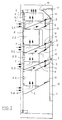
- la figure 1 est une vue de face partiellement écorchée d'une armoire électronique équipée d'un dispositif de ventilation selon l'invention ;
- la figure 2 est une vue en coupe schématique selon un plan vertical.
- Figure 1 is a partially cutaway front view of an electronic cabinet equipped with a ventilation device according to the invention;
- Figure 2 is a schematic sectional view along a vertical plane.
En référence aux figures, l'armoire électronique comporte de façon habituelle des parois latérales et arrière 1 formées par exemple de tôles soudées à une armature métallique. L'armoire contient une série de sous-ensembles électroniques 2 disposés les uns en-dessous des autres et désignés sur les figures avec un indice, le sous-ensemble 2.1 étant disposé à la partie supérieure de l'armoire électronique, le sous-ensemble 2.2 étant disposé immédiatement en-dessous, etc. Chaque sous-ensemble 2 comporte une multiplicité des cartes électroniques disposées verticalement les unes à côté des autres.With reference to the figures, the electronic cabinet usually comprises side and
Dans le mode de réalisation préféré illustré, les sous-ensembles 2 sont portés par un cadre pivotant 3 et chaque sous-ensemble est recouvert sur sa partie avant par une plaque pleine 4. Le cas échéant, la façade avant de l'armoire est protégée par une tôle ajourée non représentée assurant une protection contre les perturbations électromagnétiques.In the preferred embodiment illustrated, the sub-assemblies 2 are carried by a pivoting
Le dispositif de ventilation selon l'invention comporte des ouvertures de ventilation 5 débouchant dans la façade en-dessous de chaque sous-ensemble et des tôles déflectrices inférieures 6 disposées en-dessous de chaque ouverture 5 et inclinées vers le haut pour guider vers une direction verticale un flux d'air entrant par une ouverture de ventilation 5.The ventilation device according to the invention comprises ventilation openings 5 opening into the facade below each sub-assembly and
Dans le mode de réalisation illustré, les ouvertures de ventilation 5.1, 5.2 et 5.3 sont équipées de deux organes de ventilation forcée 7 tandis que l'ouverture de ventilation 5.4 est simplement laissée libre. Les tôles de ventilation inférieure 6 de chaque sous-ensemble sont de préférence associées à une seconde tôle déflectrice venant affleurer la partie supérieure du sous-ensemble située immédiatement en-dessous pour former un conduit de liaison 9 ayant une extrémité adjacente à un bord supérieur du sous-ensemble considéré et une extrémité opposée débouchant dans une cheminée d'évacuation 10 s'étendant verticalement le long d'une paroi de l'armoire électrique opposée à la façade. La cheminée d'évacuation 10 est par exemple réalisée au moyen d'une tôle 11 s'étendant parallèlement au panneau arrière 1 de l'armoire électronique. La cheminée 10 débouche de préférence dans la face supérieure de l'armoire électronique et est équipée d'un extracteur 12 qui sert uniquement à améliorer l'écoulement dans la cheminée 10 et éviter un bouclage des flux d'air provenant de différents sous-ensembles. Cet extracteur peut donc être d'encombrement très faible et tourner à une vitesse relativement lente ne générant pas de bruit.In the illustrated embodiment, the ventilation openings 5.1, 5.2 and 5.3 are equipped with two forced
De préférence, les conduits de liaison 9 comportent des parois latérales 13 pour former un conduit tubulaire. Les conduits de liaison 9 sont découpés en deux tronçons, l'un des tronçons étant solidaire des sous-ensembles pour pivoter avec le cadre pivotant 3 auquel ceux-ci sont fixés et l'autre tronçon étant solidaire de la cheminée 10. Lors de la fermeture de l'armoire, l'étanchéité entre les deux tronçons de chaque conduit 9 est assurée par tout moyen approprié, par exemple par des joints souples 14.Preferably, the connecting
On remarquera qu'il n'est pas nécessaire que tous les sous-ensembles soient associés à la cheminée par un conduit de liaison 9. En particulier, dans le mode de réalisation illustré, le sous-ensemble 2.1 disposé à la partie supérieure de l'armoire est ventilé par un courant d'air direct qui s'échappe à travers une tôle perforée formant une partie de la face supérieure de l'armoire.It will be noted that it is not necessary for all the sub-assemblies to be associated with the chimney by a connecting
De même, bien qu'une ventilation forcée soit souvent préférée pour augmenter le débit d'air à travers un sous-ensemble, on notera que la ventilation forcée pour un certain nombre de sous-ensembles génère en liaison avec la cheminée 10 un flux secondaire qui peut s'avérer suffisant pour ventiler un sous-ensemble particulier. Dans l'exemple décrit, le sous-ensemble 2.4 est ainsi associé à un conduit de liaison 9 dans lequel les organes de ventilation forcés 7 associés aux sous-ensembles 2.2 et 2.3 créent un flux secondaire très supérieur au flux d'air qui serait obtenu par une simple convection naturelle. Ce flux secondaire peut être important, en particulier si l'on choisit de façon convenable la section, et le cas échéant l'orientation des conduits de liaison 9 par rapport à la cheminée 10.Likewise, although forced ventilation is often preferred to increase the air flow through a sub-assembly, it will be noted that forced ventilation for a certain number of sub-assemblies generates, in connection with the
Claims (4)
- A ventilation device for an electronic cabinet comprising a front portion, opposite which are fixed sub-assemblies (2) each comprising a multiplicity of vertically disposed electronic circuit boards, ventilation openings (5) opening in the front portion below each sub-assembly (2), lower deflector plates (6) disposed below each opening (5) and inclined to guide towards a vertical direction a flow of air which enters by way of a ventilation opening, a discharge shaft (10) extending vertically along a wall of the electrical cabinet, which is opposite to the front portion, at least one sub-assembly being equipped with a connecting conduit (9) having an end adjacent to an upper edge of the sub-assembly and an opposite end opening into the shaft (10), characterised in that the sub-assemblies are carried by a pivotable panel (3) and the connecting conduits (9) comprise a fixed portion which is fixed to the shaft (10) and a movable portion which is fixed to the pivotable panel (3) and is disposed in a position opposite the fixed portion upon closure of the pivotable panel.
- A ventilation device according to claim 1 characterised in that one of the walls of a connecting conduit (9) is formed by the lower deflector plate (6) of the opening immediately above.
- A ventilation device according to claim 1 or claim 2 characterised in that at least one ventilation opening is equipped with a forced ventilation member (7).
- A ventilation device according to claim 3 characterised in that it comprises an extraction member (12) at the upper end of the shaft (10).
Applications Claiming Priority (2)
| Application Number | Priority Date | Filing Date | Title |
|---|---|---|---|
| FR9013797 | 1990-11-07 | ||
| FR9013797A FR2668875B1 (en) | 1990-11-07 | 1990-11-07 | VENTILATION DEVICE FOR AN ELECTRONIC CABINET. |
Publications (2)
| Publication Number | Publication Date |
|---|---|
| EP0485281A1 EP0485281A1 (en) | 1992-05-13 |
| EP0485281B1 true EP0485281B1 (en) | 1994-06-29 |
Family
ID=9401930
Family Applications (1)
| Application Number | Title | Priority Date | Filing Date |
|---|---|---|---|
| EP19910402969 Expired - Lifetime EP0485281B1 (en) | 1990-11-07 | 1991-11-06 | Ventilation device for an electronic cabinet |
Country Status (5)
| Country | Link |
|---|---|
| EP (1) | EP0485281B1 (en) |
| DE (1) | DE69102691T2 (en) |
| DK (1) | DK0485281T3 (en) |
| ES (1) | ES2059087T3 (en) |
| FR (1) | FR2668875B1 (en) |
Cited By (1)
| Publication number | Priority date | Publication date | Assignee | Title |
|---|---|---|---|---|
| CN105377000A (en) * | 2015-11-27 | 2016-03-02 | 国网黑龙江省电力有限公司信息通信公司 | Cabinet ventilation and flow guide device |
Families Citing this family (11)
| Publication number | Priority date | Publication date | Assignee | Title |
|---|---|---|---|---|
| JP3236137B2 (en) * | 1993-07-30 | 2001-12-10 | 富士通株式会社 | Semiconductor element cooling device |
| DE19719507A1 (en) * | 1997-05-09 | 1998-11-12 | Alsthom Cge Alcatel | Rack with subrack and ventilation device |
| EP1038103A1 (en) * | 1997-12-08 | 2000-09-27 | Siemens Aktiengesellschaft | Wind power plat and method for cooling a generator in a wind power plant |
| US6127663A (en) * | 1998-10-09 | 2000-10-03 | Ericsson Inc. | Electronics cabinet cooling system |
| DE19944232C2 (en) * | 1999-09-15 | 2001-09-27 | Loh Kg Hailo Werk | Arrangement for installation in a closet |
| WO2012166031A1 (en) * | 2011-06-01 | 2012-12-06 | Telefonaktiebolaget L M Ericsson (Publ) | Cooling of electronic components in an enclosure |
| US9266681B2 (en) * | 2012-10-11 | 2016-02-23 | Nordson Corporation | Hot melt systems, feeder devices and methods for moving particulate hot melt adhesive |
| CN112312725A (en) * | 2019-07-29 | 2021-02-02 | 中兴通讯股份有限公司 | Communication equipment |
| CN110621146B (en) * | 2019-11-25 | 2020-04-03 | 深圳市科信通信技术股份有限公司 | Cabinet is concentrated to outdoor BBU |
| CN111601486A (en) * | 2020-07-02 | 2020-08-28 | 中国电子科技集团公司第十四研究所 | Novel electronic equipment air-cooled subrack |
| CN114249011A (en) * | 2021-11-12 | 2022-03-29 | 山东省农业科学院 | Storage cabinet and system before and after peony division treatment |
Family Cites Families (4)
| Publication number | Priority date | Publication date | Assignee | Title |
|---|---|---|---|---|
| DE3107683A1 (en) * | 1981-02-28 | 1982-09-16 | Brown, Boveri & Cie Ag, 6800 Mannheim | CABINET FOR RECEIVING ELECTRICAL AND / OR ELECTRONIC COMPONENTS |
| SE456547B (en) * | 1984-12-07 | 1988-10-10 | Ericsson Telefon Ab L M | DEVICE FOR COOLING CIRCUITS |
| JPS61198799A (en) * | 1985-02-28 | 1986-09-03 | 株式会社東芝 | Connectable box construction |
| GB8704411D0 (en) * | 1987-02-25 | 1987-04-01 | Gen Electric Co Plc | Cabinet |
-
1990
- 1990-11-07 FR FR9013797A patent/FR2668875B1/en not_active Expired - Fee Related
-
1991
- 1991-11-06 EP EP19910402969 patent/EP0485281B1/en not_active Expired - Lifetime
- 1991-11-06 DK DK91402969T patent/DK0485281T3/en active
- 1991-11-06 DE DE1991602691 patent/DE69102691T2/en not_active Expired - Fee Related
- 1991-11-06 ES ES91402969T patent/ES2059087T3/en not_active Expired - Lifetime
Cited By (2)
| Publication number | Priority date | Publication date | Assignee | Title |
|---|---|---|---|---|
| CN105377000A (en) * | 2015-11-27 | 2016-03-02 | 国网黑龙江省电力有限公司信息通信公司 | Cabinet ventilation and flow guide device |
| CN105377000B (en) * | 2015-11-27 | 2018-04-17 | 国网黑龙江省电力有限公司信息通信公司 | A kind of cabinet-type ventilation guiding device |
Also Published As
| Publication number | Publication date |
|---|---|
| ES2059087T3 (en) | 1994-11-01 |
| DE69102691D1 (en) | 1994-08-04 |
| DK0485281T3 (en) | 1994-11-07 |
| EP0485281A1 (en) | 1992-05-13 |
| FR2668875B1 (en) | 1993-02-05 |
| DE69102691T2 (en) | 1995-03-02 |
| FR2668875A1 (en) | 1992-05-07 |
Similar Documents
| Publication | Publication Date | Title |
|---|---|---|
| EP0485281B1 (en) | Ventilation device for an electronic cabinet | |
| EP2098105B1 (en) | Electronic device housing cooled by natural and forced ventilation | |
| FR2905556A1 (en) | ELECTRONIC BAY ASSOCIATING NATURAL CONVECTION AND FORCE AIR CIRCULATION FOR ITS COOLING | |
| FR2889250A1 (en) | PROPELLER ASSEMBLY FOR AIRCRAFT AND AIRCRAFT COMPRISING AT LEAST ONE SUCH PROPELLER ASSEMBLY | |
| EP0583180B1 (en) | Cooling system for a door of a domestic cooking oven | |
| EP1365203B1 (en) | Heat exchanger for aircraft air conditioning system and propulsion system including same | |
| EP3551501B1 (en) | Heat dissipation device for a multimedia control unit | |
| EP1907781A2 (en) | Heat exchanger, propulsion unit and aircraft provided therewith | |
| EP3664234A1 (en) | Ventilation unit for an electrical cabinet | |
| EP0545223B1 (en) | Cabinet for electronic equipment, particularly for telecommunications | |
| FR2514472A1 (en) | SELF-VENTILATED COOKER AND METHOD FOR INSTALLATION | |
| CA2030979A1 (en) | Electromagnetic compatibility vertical structure for transmission equipment control systems, particularly microwave transmission equipment control systems | |
| FR2493667A1 (en) | COOLING DEVICE FOR AN INSTALLATION CONTAINING ELECTRONIC OR TELECOMMUNICATIONS EQUIPMENT | |
| FR2618529A1 (en) | SUPPLEMENTARY VENTILATION CIRCUIT FOR COMBINED ELECTRO-DOMESTIC OVEN | |
| EP2374385A1 (en) | Infrared cooking appliance | |
| EP1059715B1 (en) | Partitioned Air insulated Medium voltage switchgear with overpressure flaps | |
| EP1346447B1 (en) | Integrated wiring system for electrical cabinet | |
| JP4063471B2 (en) | Power supply device | |
| WO2020058610A1 (en) | Heat exchanger module for a motor vehicle | |
| EP3503673A1 (en) | Hob and system for cooling the hob | |
| FR2577306A1 (en) | Heating apparatus operating with gaseous fuels and intended to be connected to a smoke duct | |
| EP3372899B1 (en) | Stove with multilateral view of the flame | |
| EP1956620A2 (en) | Disconnector, in particular for a railway vehicle | |
| FR2788331A1 (en) | BURNER BOX WITH NOZZLES ADJUSTABLE BY A COMMON ROD | |
| EP0094876A1 (en) | Recuperative heat exchanger with a combined convection and radiation effect |
Legal Events
| Date | Code | Title | Description |
|---|---|---|---|
| PUAI | Public reference made under article 153(3) epc to a published international application that has entered the european phase |
Free format text: ORIGINAL CODE: 0009012 |
|
| 17P | Request for examination filed |
Effective date: 19911112 |
|
| AK | Designated contracting states |
Kind code of ref document: A1 Designated state(s): BE CH DE DK ES FR GB IT LI LU NL SE |
|
| 17Q | First examination report despatched |
Effective date: 19931124 |
|
| GRAA | (expected) grant |
Free format text: ORIGINAL CODE: 0009210 |
|
| AK | Designated contracting states |
Kind code of ref document: B1 Designated state(s): BE CH DE DK ES FR GB IT LI LU NL SE |
|
| REF | Corresponds to: |
Ref document number: 69102691 Country of ref document: DE Date of ref document: 19940804 |
|
| ITF | It: translation for a ep patent filed |
Owner name: BARZANO' E ZANARDO MILANO S.P.A. |
|
| GBT | Gb: translation of ep patent filed (gb section 77(6)(a)/1977) |
Effective date: 19940831 |
|
| REG | Reference to a national code |
Ref country code: ES Ref legal event code: FG2A Ref document number: 2059087 Country of ref document: ES Kind code of ref document: T3 |
|
| REG | Reference to a national code |
Ref country code: DK Ref legal event code: T3 |
|
| EAL | Se: european patent in force in sweden |
Ref document number: 91402969.9 |
|
| PLBI | Opposition filed |
Free format text: ORIGINAL CODE: 0009260 |
|
| 26 | Opposition filed |
Opponent name: PHILIPS PATENTVERWALTUNG GMBH Effective date: 19950314 |
|
| NLR1 | Nl: opposition has been filed with the epo |
Opponent name: PHILIPS PATENTVERWALTUNG GMBH |
|
| PLBF | Reply of patent proprietor to notice(s) of opposition |
Free format text: ORIGINAL CODE: EPIDOS OBSO |
|
| PLBL | Opposition procedure terminated |
Free format text: ORIGINAL CODE: EPIDOS OPPC |
|
| PLBM | Termination of opposition procedure: date of legal effect published |
Free format text: ORIGINAL CODE: 0009276 |
|
| STAA | Information on the status of an ep patent application or granted ep patent |
Free format text: STATUS: OPPOSITION PROCEDURE CLOSED |
|
| 27C | Opposition proceedings terminated |
Effective date: 19960229 |
|
| NLR2 | Nl: decision of opposition | ||
| PGFP | Annual fee paid to national office [announced via postgrant information from national office to epo] |
Ref country code: LU Payment date: 19980106 Year of fee payment: 7 |
|
| PG25 | Lapsed in a contracting state [announced via postgrant information from national office to epo] |
Ref country code: LU Free format text: LAPSE BECAUSE OF NON-PAYMENT OF DUE FEES Effective date: 19981106 |
|
| PGFP | Annual fee paid to national office [announced via postgrant information from national office to epo] |
Ref country code: DK Payment date: 19981127 Year of fee payment: 8 |
|
| PGFP | Annual fee paid to national office [announced via postgrant information from national office to epo] |
Ref country code: NL Payment date: 19981130 Year of fee payment: 8 Ref country code: ES Payment date: 19981130 Year of fee payment: 8 |
|
| PGFP | Annual fee paid to national office [announced via postgrant information from national office to epo] |
Ref country code: BE Payment date: 19981209 Year of fee payment: 8 |
|
| PG25 | Lapsed in a contracting state [announced via postgrant information from national office to epo] |
Ref country code: ES Free format text: LAPSE BECAUSE OF NON-PAYMENT OF DUE FEES Effective date: 19991107 |
|
| PG25 | Lapsed in a contracting state [announced via postgrant information from national office to epo] |
Ref country code: DK Free format text: LAPSE BECAUSE OF NON-PAYMENT OF DUE FEES Effective date: 19991130 Ref country code: BE Free format text: LAPSE BECAUSE OF NON-PAYMENT OF DUE FEES Effective date: 19991130 |
|
| BERE | Be: lapsed |
Owner name: MATRA COMMUNICATION Effective date: 19991130 |
|
| PG25 | Lapsed in a contracting state [announced via postgrant information from national office to epo] |
Ref country code: NL Free format text: LAPSE BECAUSE OF NON-PAYMENT OF DUE FEES Effective date: 20000601 |
|
| NLV4 | Nl: lapsed or anulled due to non-payment of the annual fee |
Effective date: 20000601 |
|
| REG | Reference to a national code |
Ref country code: DK Ref legal event code: EBP |
|
| PGFP | Annual fee paid to national office [announced via postgrant information from national office to epo] |
Ref country code: SE Payment date: 20001123 Year of fee payment: 10 |
|
| PGFP | Annual fee paid to national office [announced via postgrant information from national office to epo] |
Ref country code: CH Payment date: 20001128 Year of fee payment: 10 |
|
| PGFP | Annual fee paid to national office [announced via postgrant information from national office to epo] |
Ref country code: GB Payment date: 20011102 Year of fee payment: 11 |
|
| PG25 | Lapsed in a contracting state [announced via postgrant information from national office to epo] |
Ref country code: SE Free format text: LAPSE BECAUSE OF NON-PAYMENT OF DUE FEES Effective date: 20011107 |
|
| PG25 | Lapsed in a contracting state [announced via postgrant information from national office to epo] |
Ref country code: LI Free format text: LAPSE BECAUSE OF NON-PAYMENT OF DUE FEES Effective date: 20011130 Ref country code: CH Free format text: LAPSE BECAUSE OF NON-PAYMENT OF DUE FEES Effective date: 20011130 |
|
| PGFP | Annual fee paid to national office [announced via postgrant information from national office to epo] |
Ref country code: DE Payment date: 20011228 Year of fee payment: 11 |
|
| REG | Reference to a national code |
Ref country code: GB Ref legal event code: IF02 |
|
| EUG | Se: european patent has lapsed |
Ref document number: 91402969.9 |
|
| REG | Reference to a national code |
Ref country code: CH Ref legal event code: PL |
|
| PG25 | Lapsed in a contracting state [announced via postgrant information from national office to epo] |
Ref country code: GB Free format text: LAPSE BECAUSE OF NON-PAYMENT OF DUE FEES Effective date: 20021106 |
|
| PG25 | Lapsed in a contracting state [announced via postgrant information from national office to epo] |
Ref country code: DE Free format text: LAPSE BECAUSE OF NON-PAYMENT OF DUE FEES Effective date: 20030603 |
|
| GBPC | Gb: european patent ceased through non-payment of renewal fee | ||
| PGFP | Annual fee paid to national office [announced via postgrant information from national office to epo] |
Ref country code: FR Payment date: 20031105 Year of fee payment: 13 |
|
| REG | Reference to a national code |
Ref country code: ES Ref legal event code: FD2A Effective date: 20001214 |
|
| PG25 | Lapsed in a contracting state [announced via postgrant information from national office to epo] |
Ref country code: FR Free format text: LAPSE BECAUSE OF NON-PAYMENT OF DUE FEES Effective date: 20050729 |
|
| REG | Reference to a national code |
Ref country code: FR Ref legal event code: ST |
|
| PG25 | Lapsed in a contracting state [announced via postgrant information from national office to epo] |
Ref country code: IT Free format text: LAPSE BECAUSE OF NON-PAYMENT OF DUE FEES;WARNING: LAPSES OF ITALIAN PATENTS WITH EFFECTIVE DATE BEFORE 2007 MAY HAVE OCCURRED AT ANY TIME BEFORE 2007. THE CORRECT EFFECTIVE DATE MAY BE DIFFERENT FROM THE ONE RECORDED. Effective date: 20051106 |