EP0485089A2 - Engine exhaust gas recirculation system - Google Patents
Engine exhaust gas recirculation system Download PDFInfo
- Publication number
- EP0485089A2 EP0485089A2 EP91309877A EP91309877A EP0485089A2 EP 0485089 A2 EP0485089 A2 EP 0485089A2 EP 91309877 A EP91309877 A EP 91309877A EP 91309877 A EP91309877 A EP 91309877A EP 0485089 A2 EP0485089 A2 EP 0485089A2
- Authority
- EP
- European Patent Office
- Prior art keywords
- exhaust gas
- engine
- passage
- recirculation
- cylinder
- Prior art date
- Legal status (The legal status is an assumption and is not a legal conclusion. Google has not performed a legal analysis and makes no representation as to the accuracy of the status listed.)
- Granted
Links
Images


Classifications
-
- F—MECHANICAL ENGINEERING; LIGHTING; HEATING; WEAPONS; BLASTING
- F02—COMBUSTION ENGINES; HOT-GAS OR COMBUSTION-PRODUCT ENGINE PLANTS
- F02D—CONTROLLING COMBUSTION ENGINES
- F02D41/00—Electrical control of supply of combustible mixture or its constituents
- F02D41/0025—Controlling engines characterised by use of non-liquid fuels, pluralities of fuels, or non-fuel substances added to the combustible mixtures
- F02D41/0047—Controlling exhaust gas recirculation [EGR]
- F02D41/005—Controlling exhaust gas recirculation [EGR] according to engine operating conditions
-
- F—MECHANICAL ENGINEERING; LIGHTING; HEATING; WEAPONS; BLASTING
- F01—MACHINES OR ENGINES IN GENERAL; ENGINE PLANTS IN GENERAL; STEAM ENGINES
- F01N—GAS-FLOW SILENCERS OR EXHAUST APPARATUS FOR MACHINES OR ENGINES IN GENERAL; GAS-FLOW SILENCERS OR EXHAUST APPARATUS FOR INTERNAL COMBUSTION ENGINES
- F01N3/00—Exhaust or silencing apparatus having means for purifying, rendering innocuous, or otherwise treating exhaust
- F01N3/08—Exhaust or silencing apparatus having means for purifying, rendering innocuous, or otherwise treating exhaust for rendering innocuous
- F01N3/10—Exhaust or silencing apparatus having means for purifying, rendering innocuous, or otherwise treating exhaust for rendering innocuous by thermal or catalytic conversion of noxious components of exhaust
- F01N3/18—Exhaust or silencing apparatus having means for purifying, rendering innocuous, or otherwise treating exhaust for rendering innocuous by thermal or catalytic conversion of noxious components of exhaust characterised by methods of operation; Control
- F01N3/22—Control of additional air supply only, e.g. using by-passes or variable air pump drives
-
- F—MECHANICAL ENGINEERING; LIGHTING; HEATING; WEAPONS; BLASTING
- F02—COMBUSTION ENGINES; HOT-GAS OR COMBUSTION-PRODUCT ENGINE PLANTS
- F02D—CONTROLLING COMBUSTION ENGINES
- F02D41/00—Electrical control of supply of combustible mixture or its constituents
- F02D41/0025—Controlling engines characterised by use of non-liquid fuels, pluralities of fuels, or non-fuel substances added to the combustible mixtures
- F02D41/0047—Controlling exhaust gas recirculation [EGR]
- F02D41/0065—Specific aspects of external EGR control
- F02D41/0072—Estimating, calculating or determining the EGR rate, amount or flow
-
- F—MECHANICAL ENGINEERING; LIGHTING; HEATING; WEAPONS; BLASTING
- F02—COMBUSTION ENGINES; HOT-GAS OR COMBUSTION-PRODUCT ENGINE PLANTS
- F02M—SUPPLYING COMBUSTION ENGINES IN GENERAL WITH COMBUSTIBLE MIXTURES OR CONSTITUENTS THEREOF
- F02M26/00—Engine-pertinent apparatus for adding exhaust gases to combustion-air, main fuel or fuel-air mixture, e.g. by exhaust gas recirculation [EGR] systems
- F02M26/01—Internal exhaust gas recirculation, i.e. wherein the residual exhaust gases are trapped in the cylinder or pushed back from the intake or the exhaust manifold into the combustion chamber without the use of additional passages
-
- F—MECHANICAL ENGINEERING; LIGHTING; HEATING; WEAPONS; BLASTING
- F02—COMBUSTION ENGINES; HOT-GAS OR COMBUSTION-PRODUCT ENGINE PLANTS
- F02M—SUPPLYING COMBUSTION ENGINES IN GENERAL WITH COMBUSTIBLE MIXTURES OR CONSTITUENTS THEREOF
- F02M26/00—Engine-pertinent apparatus for adding exhaust gases to combustion-air, main fuel or fuel-air mixture, e.g. by exhaust gas recirculation [EGR] systems
- F02M26/13—Arrangement or layout of EGR passages, e.g. in relation to specific engine parts or for incorporation of accessories
- F02M26/17—Arrangement or layout of EGR passages, e.g. in relation to specific engine parts or for incorporation of accessories in relation to the intake system
- F02M26/20—Feeding recirculated exhaust gases directly into the combustion chambers or into the intake runners
-
- F—MECHANICAL ENGINEERING; LIGHTING; HEATING; WEAPONS; BLASTING
- F02—COMBUSTION ENGINES; HOT-GAS OR COMBUSTION-PRODUCT ENGINE PLANTS
- F02M—SUPPLYING COMBUSTION ENGINES IN GENERAL WITH COMBUSTIBLE MIXTURES OR CONSTITUENTS THEREOF
- F02M26/00—Engine-pertinent apparatus for adding exhaust gases to combustion-air, main fuel or fuel-air mixture, e.g. by exhaust gas recirculation [EGR] systems
- F02M26/13—Arrangement or layout of EGR passages, e.g. in relation to specific engine parts or for incorporation of accessories
- F02M26/40—Arrangement or layout of EGR passages, e.g. in relation to specific engine parts or for incorporation of accessories with timing means in the recirculation passage, e.g. cyclically operating valves or regenerators; with arrangements involving pressure pulsations
-
- F—MECHANICAL ENGINEERING; LIGHTING; HEATING; WEAPONS; BLASTING
- F02—COMBUSTION ENGINES; HOT-GAS OR COMBUSTION-PRODUCT ENGINE PLANTS
- F02M—SUPPLYING COMBUSTION ENGINES IN GENERAL WITH COMBUSTIBLE MIXTURES OR CONSTITUENTS THEREOF
- F02M26/00—Engine-pertinent apparatus for adding exhaust gases to combustion-air, main fuel or fuel-air mixture, e.g. by exhaust gas recirculation [EGR] systems
- F02M26/52—Systems for actuating EGR valves
- F02M26/59—Systems for actuating EGR valves using positive pressure actuators; Check valves therefor
- F02M26/61—Systems for actuating EGR valves using positive pressure actuators; Check valves therefor in response to exhaust pressure
-
- F—MECHANICAL ENGINEERING; LIGHTING; HEATING; WEAPONS; BLASTING
- F02—COMBUSTION ENGINES; HOT-GAS OR COMBUSTION-PRODUCT ENGINE PLANTS
- F02D—CONTROLLING COMBUSTION ENGINES
- F02D2200/00—Input parameters for engine control
- F02D2200/02—Input parameters for engine control the parameters being related to the engine
- F02D2200/04—Engine intake system parameters
- F02D2200/0406—Intake manifold pressure
-
- F—MECHANICAL ENGINEERING; LIGHTING; HEATING; WEAPONS; BLASTING
- F02—COMBUSTION ENGINES; HOT-GAS OR COMBUSTION-PRODUCT ENGINE PLANTS
- F02D—CONTROLLING COMBUSTION ENGINES
- F02D2200/00—Input parameters for engine control
- F02D2200/02—Input parameters for engine control the parameters being related to the engine
- F02D2200/04—Engine intake system parameters
- F02D2200/0411—Volumetric efficiency
-
- Y—GENERAL TAGGING OF NEW TECHNOLOGICAL DEVELOPMENTS; GENERAL TAGGING OF CROSS-SECTIONAL TECHNOLOGIES SPANNING OVER SEVERAL SECTIONS OF THE IPC; TECHNICAL SUBJECTS COVERED BY FORMER USPC CROSS-REFERENCE ART COLLECTIONS [XRACs] AND DIGESTS
- Y02—TECHNOLOGIES OR APPLICATIONS FOR MITIGATION OR ADAPTATION AGAINST CLIMATE CHANGE
- Y02T—CLIMATE CHANGE MITIGATION TECHNOLOGIES RELATED TO TRANSPORTATION
- Y02T10/00—Road transport of goods or passengers
- Y02T10/10—Internal combustion engine [ICE] based vehicles
- Y02T10/40—Engine management systems
Definitions
- This invention relates to an internal combustion engine exhaust gas recirculation system.
- a hole is made in an intake pipe for the introduction of exhaust recirculation, the hole being formed in the trunk of the intake manifold.
- the exhaust introduction hole formed in the intake pipe is spaced well apart from the intake valve portion.
- the exhaust gas and the intake air are completely mixed in a collection box so that the exhaust gas is distributed over the gas when it is introduced into the cylinder. If too much exhaust gas is recirculated, combustion is deteriorated.
- the present invention seeks to provide an engine exhaust gas recirculation system which does not deteriorate engine performance, even if excess exhaust gas is recirculated.
- an engine exhaust gas recirculation system comprising:
- the present invention in order to achieve the above-specified object, renders the exhaust gas distribution in the cylinder uniform.
- hole means are provided in the vicinity of an intake valve disposed in said intake passage and said timing means includes camshaft means for driving inlet and exhaust valves of said cylinder of said engine and fuel injection timing means.
- a multicylinder engine hole means are provided in the vicinity of an intake valve disposed in said intake passage and said timing means comprise means for directing exhaust gas in said recirculation passage to a predetermined one intake valve of a plurality of intake valves disposed in a multicylinder engine.
- said timing means comprises a distributor having a plurality of outlet ports corresponding to the number of cylinders of said multicylinder engine, means defining a rotatable passage in said distributor for connecting an inlet of said distributor for receiving said exhaust gas and for feeding said exhaust gas to a respective one of said outlets.
- hole means are provided in the vicinity of an intake valve disposed in said intake passage and a recirculation control valve is provided in said recirculation passage downstream of said hole means, and said timing means includes said recirculation control valve and said inlet valve whereby exhaust gas is input to a cylinder of said engine in dependence upon pressure changes at each side of said recirculation control valve.
- said recirculation control valve is a flap valve or a spring biassed valve.
- said exhaust gas recirculation passage is connected to a hole means in a side of said cylinder positioned to be above a piston of said cylinder when said piston is at bottom dead center and said timing means includes a crankshaft for reciprocating said piston.
- recirculation flow detection means are provided for determining the recirculation flow of the exhaust gas on the basis of a load signal when the exhaust gas is recirculated and a load signal when the exhaust gas is not recirculated.
- control means are provided for detecting the degree of roughness of the internal combustion engine to feed said recirculation control valve with a control signal for controlling the recirculation flow in accordance with said degree of roughness.
- control means determines an allowable maximum recirculation flow in accordance with said degree of roughness, thereby to determine said control signal.
- a recirculation control valve is disposed in said exhaust gas recirculation passage for recirculating the exhaust gas at a predetermined timing and for a predetermined period during the strokes of said internal combustion engine.
- the exhaust gas introduction hole is formed in the vicinity of the intake valve, the distribution of the exhaust gas is concentrated around the intake valve.
- the suction stroke begins to open the intake valve, the exhaust gas is sucked at an initial stage of suction so that its distribution in the cylinder is heterogeneous. Specifically, the exhaust gas is distributed in the lower portion of the cylinder, but a fresh air/fuel mixture is distributed in the cylinder upper portion. Even if much exhaust gas is introduced, the combustion is not deteriorated because the fresh mixture is distributed around the ignition plug in the upper portion of the cylinder.
- the allowable maximum exhaust gas can be introduced on the basis of the degree of engine running roughness, which is determined by an oxygen sensor attached to the exhaust pipe. Much recirculation flow will reduce the fuel consumption and the NOx, but too much flow will lead to a misfire. The maximum exhaust flow is always introduced by detecting the misfire state with the oxygen sensor.
- FIG. 1 One embodiment of the present invention will be described with reference to Figure 1 in which an exhaust gas is introduced into an intake pipe 2 by way of a passage 3 connecting an exhaust pipe 1 and the intake pipe 2.
- the passage 3 is equipped with a flow control valve 4.
- the passage 3 has an opening or hole 6 in the vicinity of an intake valve 5 of the intake pipe 2.
- a suction air flow sensor 7 and an oxygen sensor 8 have their signals inputted to a controller 9 to detect the exhaust gas recirculation (which will be referred to herein as "EGR”) flow thereby to determine the optimum EGR flow.
- the EGR flow thus determined is fed after it has been metered by the control valve 4.
- the inlet valve and exhaust valve (not shown) of the engine are timingly controlled by a camshaft 81.
- FIG. 1 The structure of Figure 1 is shown for all the cylinders of a four-cylinder engine in Figure 2.
- the exhaust gas is fed via the passage 3 from the hole 6 which is opened in the vicinity of the intake valve 5 of each cylinder.
- communications are provided among the exhaust introduction holes 6 into the individual cylinders 11.
- an EGR pipe could extend within the intake pipe 2 to introduce exhaust gas as close as possible to the inlet valve.
- Figure 3 shows the behaviour of the exhaust gas and the fresh air/fuel mixture in each of the cylinder 11 and the intake pipe 2 at the individual strokes. These individual strokes of the engine are shown in Figure 3(a). The behaviour of the gas at the instants (b) to (e) of Figure 3(a) are shown at the corresponding Figures 3(b) to (e).
- Figure 3(b) shows the state at the end period of the exhaust stroke.
- solid circles indicate the exhaust gas
- clear circles indicate the fresh air/fuel mixture. Since the opening 6 is located near the closed intake valve 5 ( Figure 3(b)), the exhaust gas is fed therethrough upward to an upstream collector 12. As a result, the exhaust gas is exclusively distributed in the vicinity of the intake valve 5 of the intake pipe 2.
- Figures 4(a) and (b) show one embodiment of the fuel injection method of the present inventioin.
- Figure 4(a) shows the relationship between the suction stroke and the fuel injection time.
- the fuel is injected at the latter half of the suction stroke. This injection is timed when much fresh mixture is sucked into the cylinder, as shown in Figure 3(d).
- the injection ending timing tref is determined to prevent a failure in the event that the injection is not completed during the suction stroke.
- the injection time is elongated, if desired, toward the initial time of the suction stroke, as indicated at (A), (B), (C) and (D), while leaving the timing tref unchanged. In short, the injection beginning timing is changed to change the injection time.
- Figure 5 shows one embodiment of the control for executing the aforementioned operations.
- Figure 5 maps the EGR ratio with the R.P.M. and load of the engine.
- the controller 9 is stored therein with EGR ratio curves a to e.
- the controller 9 reads the EGR ratios and operates the control valve 4 to feed the target EGR flow.
- Figure 6 shows a flow chart for determining the fuel injection timing.
- the determined injection pulse width T i is read out, and the R.P.M. N is read to determine the crank angle to which the pulse width T i corresponds. In other words, a crank angle ⁇ i corresponding to the time T i is determined.
- an injection beginning timing ⁇ inj is determined from the injection ending timing tref shown in Figure 4.
- the injection valve is opened at the timing ⁇ inj .
- Figure 7 shows another embodiment, in which the passage 3 is equipped with a timing means including a distributor 20.
- the distributor 20 is rotated in synchronism with the engine rotation.
- the exhaust gas flows to the intake pipe 2 when an opening 21 in the distributor comes into registration with a respective distribution pipe 22 for each of the engine cylinders.
- the exhaust gas is fed to the intake pipe at a predetermined timing of the engine strokes.
- the rotation of the distributor may be effected by drive from the crankshaft or by a motor (both not shown).
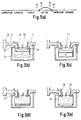
- Figure 8 shows the engine strokes of each of the four cylinders and the flow behaviour of the EGR gas, as exemplified by the cylinder No. 1.
- the distributor 20 is so set that the EGR gas may flow exclusively at the first half of the suction stroke of the engine.
- the distributor sets the distribution pipe 22 to feed firstly the cylinder No. 1 and then the cylinders Nos. 3, 4 and 2 with the EGR gas.
- each cylinder can be fed with the gas only at its first half of the suction stroke.
- Figures 9(a) to (e) show the behaviour of the gas in the cylinder 11 and the intake pipe 2 of the embodiment of Figure 7.
- Figure 9(a) shows the engine strokes.
- the behaviour of the gas at the timings corresponding to (b) to (e) of Figure 9(a) are shown in at the corresponding Figures 9(b) to (e).
- the distributor 20 has rotated to a position to feed the gas to the distribution pipe 22 corresponding to that cylinder.
- the intake pipe 2 is fed with the exhaust gas.
- the solid circles in Figure 9(b) indicate the exhaust gas and the clear circles denote air/fuel mixture.
- the distributor 20 has rotated to feed no exhaust gas to the distribution pipe 22.
- FIG 10 shows a further embodiment of this invention in which the distribution pipe 22 corresponding to each cylinder is equipped with a flap valve 30 which is to be opened or closed in dependence upon the exhaust pressure.
- the moving part is only the valve 30 so that the structure is greatly simplified.
- the distribution pipes corresponding to other individual cylinders are also equipped with the valves 30. More particularly, as shown in Figure 11(a), this further embodiment is constructed to have a valve 30.
- the exhaust gas is introduced into a passage 32.
- the valve 30 changes its position from closed (shown in broken lines) to open (shown in solid line) so that the gas flows, as indicated by arrow headed lines. If the pressure of the exhaust gas of the passage 32 is then overcome by the set force of the valve 30, the valve 30 is closed, as indicated by the broken lines.
- the exhaust gas can be fed to the intake pipe only when the exhaust pressure is high.
- Figure 11(b) shows another type of valve 30 that may be used in the further embodiment in which a spring biassed needle valve 34 is moved upward to feed the exhaust gas to the intake pipe when the pressure of the exhaust gas of a passage 35 exceeds the gas pressure of an upstream passage 36.
- the pressure, at which the valve 34 is opened, is set in terms of the force of a compression spring 37.
- Figures 12(a) to (c) show the pressure change in the exhaust gas and the operations of the valve 30.
- Figure 12(a) shows the pressure change in the exhaust gas in the exhaust pipe. The pressure rises in a manner to correspond to the exhaust stroke of each cylinder so that it performs periodical pulsations, as shown. This pressure acts upon the valve 30 associated with each cylinder.
- Figure 12(b) shows the operations of the individual valves 30.
- the cylinder No. 3 is in the suction stroke so that the vacuum in the intake pipe 2 in the vicinity of the intake valve of the cylinder No. 3 is high.
- the valve 30 is opened by the pressure difference between that vacuum and the positive pressure of the exhaust gas.
- the EGR gas can be laminated by the simple structure because the gas can be fed only for a predetermined period of the engine strokes, as shown in Figure 12(c).
- FIG 13 shows an example of the application of this invention to an engine having each cylinder 11 equipped with a plurality (two) of intake valves 5a and 5b.
- the intake pipe 2 is branched (as indicated at 35a and 35b) in correspondence with the intake valves 5a and 5b.
- Either of the branched intake pipes 35a and 35b may be formed with the hole 6 for introducing the exhaust gas, but in the exemplary embodiment the hole is shown in pipe 35b.
- the exhaust gas is likewise fed only to the intake pipe corresponding to one of the intake valves.
- the EGR gas is laminated by offsetting the feeder. The flow of the exhaust gas at this time may be continuous or intermittent.
- Figure 14 shows the behaviour of the gas in the cylinder of such a case. Since the exhaust gas flows only from one intake valve 5b, the exhaust gas is distributed in the outer circumference of the cylinder, as shown in solid circles. The fresh mixture, as shown by clear circles, is distributed in the inside of the cylinder 11. Due to these distributions, the fresh mixture is concentrated around the ignition plug 13 so that the combustion is not deteriorated even if much EGR gas is introduced.
- Figures 15(a) to (c) show yet another embodiment of the EGr gas feeding method.
- the exhaust gas is fed not to the intake pipe but directly into the inside of the cylinder 11 of the engine.
- the cylinder 11 has an exhaust gas feed hole 36 formed in a lower portion thereof.
- Figure 15(a) shows the suction stroke, in which a piston 37 driven by a crankshaft 82 is moving to its lower position. In this state, only the fresh mixture flows into the cylinder 11 through the intake valve 5.
- the hole 36 is arranged to be opened when the piston comes close to the bottom dead center, as indicated at Figure 15(b).
- Figure 16 shows the method of detecting the amount of the EGR gas. This method can be applied to the system having the structures of Figures 1, 7 and 10.
- Figure 16(a) shows the amount of the EGR gas to flow through the passage 3.
- Figure 16(b) shows the output value V AFM of the intake air flow sensor 7 wherein the air quantity detected by the air flow sensor increases when EGR is switched OFF.
- the output value V AFM while the EGR gas is being fed, as shown in Figure 16(a), is designated at V1, as shown in Figure 16(b).
- V AFM when the EGR gas is OFF, is designated at V2.
- the EGR ratio is determined from the difference between V1 and V2. Since the EGR gas is introduced downstream (at the engine side) of the intake air flow sensor 7, the intake air flow changes in dependence upon the presence or absence of the gas flow.
- FIG 17 shows a flow diagram at the detection time.
- the throttle opening ⁇ th and the engine R.P.M. N are read (at Step 40). It is decided (at Step 41) whether or not the values ⁇ th and N are in the steady state. If NOT in the steady state, this program flow is ended. If in the steady state, the value V1 for the EGR ON is read (at Step 42). Next, the EGR is turned OFF (at Step 43), and the value V2 at this time is read (at Step 44). The EGR is turned ON again (at Step 45). At this time, it is checked (at Step 46) whether or not the values ⁇ th and N have been unchanged during Steps 40 to 46.
- Figure 18 shows another method of detecting the EGR ratio in which an intake pipe pressure sensor 50 is provided in addition to the intake air flow sensor 7. With this structure, the EGR ratio can be detected even in the unsteady running state.
- a simplified model of the structure shown in Figure 18(a) is shown in Figure 18(b).
- the flow rate of the air to pass through a throttle valve 51 is designated at Q S and is detected by the air flow sensor 7.
- the pressure in the intake pipe 2 is designated at P and is detected by the pressure sensor 50.
- the flow rate of the air to flow through the throttle valve 51 into the cylinder 11 is designated at Q C .
- the EGR gas flow rate is designated at Q E .
- the values Q C and Q E are unknown.
- Figure 19(a) shows the change in the pressure P in the unsteady state.
- the pressure one cycle that is, 180 degrees in the four-cylinder four-cycle engine
- a pressure P ⁇ is designated at P ⁇ .
- an integrated value Q ⁇ S of the air flow for one stroke is shown in Figure 19(b).
- the ratio R EGR is determined on the basis of those values P ⁇ , P ⁇ and Q ⁇ s .
- Figure 20 shows a flow chart for this determination.
- the pressures P ⁇ and P ⁇ are read (at Step 52).
- the output of the air flow sensor 7 is integrated for one stroke to determine the value Q ⁇ S (at Step 53).
- the volumetric efficiency ⁇ ' changes. This is because the value ⁇ E is determined from the equation (4) by the following equation: In short, the value ⁇ changes by the value Q ⁇ E of the equation (4). In this detection method, the EGR ratio is determined from the change in the value ⁇ .
- Step 55 the equation (4) is computed.
- the value ⁇ E is determined.
- This equation (10) is computed at Step 57.
- the ratio R EGR is determined so that it may always be controlled to the target value.
- Figure 21 shows the relationship between the EGR ratio and the fuel consumption be and the exhausts of HC and NOx.
- the values be and NOx will drop.
- the values HC, be and NOx will, again, increase.
- the turning point of HC be and NOx define the limit EGR ratio. If the EGR is increased over the turning point, the engine misfires to increase the values HC and be . From the standpoint of the control, the EGR ratio to be fed is desirably determined to minimize the value be . A method of detecting the limit EGR ratio to fix it at all times will now be described.
- Figure 22 shows the principle for detecting the roughness with an oxygen sensor (herein referred to as an "O2 sensor", as shown by reference numeral 8 in Figure 1).
- Figure 22(a) shows the signal of the O2 sensor for the proper EGR ratio.
- Figure 22(b) shows the signal of the O2 sensor when the limit of the EGR ratio is exceeded.
- the signal of Figure 22(b) contains signal disturbances due to misfire. The degree of the disturbances is detected and used as the roughness of the engine. This engine roughness to be used can be detected in terms of the fluctuations of the engine R.P.M. and the vacuum in the intake pipe.
- Figure 23 shows a method for detecting the degree of roughness from the signal shown in Figure 22(b).
- An example of the circuit for the method is shown in Figure 23(a).
- the signal of an O2 sensor 60 is inputted to an amplifier 61. After amplification, the high-frequency component of the signal is extracted through a high-pass filter 62, and its peak is detected by a peak hold 63 and is used as the measurement of roughness.
- the signals (b) to (d), shown in Figure 23(a), are shown in Figures 23(b) to (d) respectively.
- the original signal ( Figure 23(b)) having passed through the high-pass filter 62 is shown in Figure 23(c). This filtered signal indicates the degree of engine roughness.
- This signal is processed for the peak hold into a level signal, as shown at Figure 23(d).
- the controller 9 decides the degree (amount) of engine roughness according to the magnitude of the signal (d).
- the value of this signal (d) is designated at V P .
- Figure 24 shows another method of detecting the degree of roughness.
- Figure 24(a) shows the original signal of the O2 sensor. This signal is compared with a constant reference value V ref by a comparator so that it is converted into a signal shown in Figure 24(b).
- the ON/OFF period of this signal (b) corresponds to the degree of engine roughness.
- the ON/OFF number of this signal (b) is counted by a counter circuit. If the reset pulses ( Figure 24(c)) are inputted to the counter circuit, they are counted up, as shown at Figure 24(d), each time the signal of Figure 24(b) is turned ON and OFF. Next, the counted value until the reset pulse is inputted is held, as shown at Figure 24(e). In terms of this hold value V C , the controller decides the degree of engine roughness. In short, the degree of roughness is determined to be higher for the higher hold valve V C .
- Figure 25 shows the relationships between the changing EGR ratio and the values HC, be , V P and V C . If the EGR exceeds the turning point at which the values HC and be increase, the values V P and V C also increase, from which the limit EGR ratio can be decided.
- FIG 26 shows a flow diagram for the limit EGR control, which corresponds to the embodiment of Figure 23.
- the value V P is read (at Step 60). It is then decided (at Step 61) whether or not the value V P exceeds a reference value V*. If the value V P is smaller than the value V*, it is decided that the limit EGR ratio is not reached yet, and the EGR ratio is increased (at Step 63). If the value V P is larger than the value V*, it is decided that the limit EGR ratio is exceeded, and the EGR ratio is decreased (at Step 62). The newly determined EGR ratios are stored in the memory (at Step 64). Thus, the controls can always be accomplished with the EGR ratio which is the closest to the limit.
- FIG 27 shows a control flow diagram for the arrangement described with regard to Figures 24 (a) to (e).
- the value V C is read (at Step 65) and is compared with the reference value V* (at Step 66). If V C > V*, the EGR ratio is decreased (at Step 67). If V c ⁇ V*, the EGR ratio is increased (at Step 68). After this, the EGR ratio is stored (at Step 69) in the memory position corresponding to the running state at that time.
- the combustion is not deteriorated even if more EGR gas is mixed in a cylinder than is possible in the system of the prior art.
- it is possible to drastically reduce the fuel consumption and the exhaust of NOx.
Abstract
Description
- This invention relates to an internal combustion engine exhaust gas recirculation system.
- In a system of the prior art, as exemplified in Japanese Patent Publication No. 25971/1979, a hole is made in an intake pipe for the introduction of exhaust recirculation, the hole being formed in the trunk of the intake manifold.
- In the aforementioned prior art, the exhaust introduction hole formed in the intake pipe is spaced well apart from the intake valve portion. As a result, the exhaust gas and the intake air are completely mixed in a collection box so that the exhaust gas is distributed over the gas when it is introduced into the cylinder. If too much exhaust gas is recirculated, combustion is deteriorated.
- The present invention seeks to provide an engine exhaust gas recirculation system which does not deteriorate engine performance, even if excess exhaust gas is recirculated.
- According to one aspect of this invention there is provided an engine exhaust gas recirculation system comprising:
- (a) an intake passage connected to feed an air/fuel mixture to an internal combustion engine;
- (b) an exhaust passage connected to discharge an exhaust gas from said internal combustion engine;
- (c) an exhaust gas recirculation passage for feeding the exhaust gas of said exhaust passage; and
- (d) timing means for feeding said portion of the exhaust gas from said exhaust passage into a cylinder in laminar form with said air/fuel mixture, such that the air/fuel mixture is adjacent an ignition plug and said portion of the exhaust gas is distributed in said cylinder away from said ignition plug.
- The present invention, in order to achieve the above-specified object, renders the exhaust gas distribution in the cylinder uniform.
- Preferably, hole means are provided in the vicinity of an intake valve disposed in said intake passage and said timing means includes camshaft means for driving inlet and exhaust valves of said cylinder of said engine and fuel injection timing means.
- In a multicylinder engine hole means are provided in the vicinity of an intake valve disposed in said intake passage and said timing means comprise means for directing exhaust gas in said recirculation passage to a predetermined one intake valve of a plurality of intake valves disposed in a multicylinder engine.
- Advantageously, said timing means comprises a distributor having a plurality of outlet ports corresponding to the number of cylinders of said multicylinder engine, means defining a rotatable passage in said distributor for connecting an inlet of said distributor for receiving said exhaust gas and for feeding said exhaust gas to a respective one of said outlets.
- Alternatively, hole means are provided in the vicinity of an intake valve disposed in said intake passage and a recirculation control valve is provided in said recirculation passage downstream of said hole means, and said timing means includes said recirculation control valve and said inlet valve whereby exhaust gas is input to a cylinder of said engine in dependence upon pressure changes at each side of said recirculation control valve.
- In such an alternative said recirculation control valve is a flap valve or a spring biassed valve.
- In another embodiment of the invention, said exhaust gas recirculation passage is connected to a hole means in a side of said cylinder positioned to be above a piston of said cylinder when said piston is at bottom dead center and said timing means includes a crankshaft for reciprocating said piston.
- Advantageously, recirculation flow detection means are provided for determining the recirculation flow of the exhaust gas on the basis of a load signal when the exhaust gas is recirculated and a load signal when the exhaust gas is not recirculated.
- Preferably, control means are provided for detecting the degree of roughness of the internal combustion engine to feed said recirculation control valve with a control signal for controlling the recirculation flow in accordance with said degree of roughness.
- Conveniently, said control means determines an allowable maximum recirculation flow in accordance with said degree of roughness, thereby to determine said control signal.
- Advantageously, a recirculation control valve is disposed in said exhaust gas recirculation passage for recirculating the exhaust gas at a predetermined timing and for a predetermined period during the strokes of said internal combustion engine.
- If the exhaust gas introduction hole is formed in the vicinity of the intake valve, the distribution of the exhaust gas is concentrated around the intake valve. When the suction stroke begins to open the intake valve, the exhaust gas is sucked at an initial stage of suction so that its distribution in the cylinder is heterogeneous. Specifically, the exhaust gas is distributed in the lower portion of the cylinder, but a fresh air/fuel mixture is distributed in the cylinder upper portion. Even if much exhaust gas is introduced, the combustion is not deteriorated because the fresh mixture is distributed around the ignition plug in the upper portion of the cylinder. Moreover, the allowable maximum exhaust gas can be introduced on the basis of the degree of engine running roughness, which is determined by an oxygen sensor attached to the exhaust pipe. Much recirculation flow will reduce the fuel consumption and the NOx, but too much flow will lead to a misfire. The maximum exhaust flow is always introduced by detecting the misfire state with the oxygen sensor.
- The invention will now be described, by way of example, with reference to the accompanying drawings in which:-
- Figure 1 shows in schematic form the structure of an engine exhaust gas recirculation system in accordance with one embodiment of this invention;
- Figure 2 shows in schematic form the structure with a multiple cylinder engine;
- Figures 3(a) to (e) and 4(a) and (b) are diagrams showing the operational priniciple of this invention;
- Figure 5 shows an exhaust gas recirculation (EGR) map;
- Figure 6 shows a control flow diagram;
- Figure 7 shows the structure of an exhaust gas recirculation system in accordance with another embodiment of this invention;
- Figures 8 and 9(a) to (e) are diagrams showing the operational principle of Figure 7;
- Figure 10 shows an exhaust gas recirculation system in accordance with a further embodiment of this invention;
- Figures 11(a) and (b) show the structure of a control valve in partial section used in Figure 10;
- Figures 12(a) to (c) are diagrams showing the operational principle of the Figure 10 embodiments;
- Figures 13 and 14 show the application of the invention of a cylinder having plural inlet valves;
- Figures 15(a) to (c) are diagrams showing the operational principle of an exhaust gas recirculation system in yet a further embodiment of the present invention;
- Figures 16(a) and (b) are graphical diagrams showing the principle for determining an exhaust gas recirculation ratio;
- Figure 17 shows a control flow diagram for the embodiment of Figure 16;
- Figures 18(a) and (b) are schematic diagrams showing another method of determining the exhaust gas recirculation (EGR) ratio;
- Figures 19(a) and (b) are graphical waveforms showing the principle of the method of Figures 18(a) and (b);
- Figure 20 shows a control flow diagram for calculating the EGR ratio;
- Figure 21 is a characteristic diagram showing the EGR ratio and various other parameters;
- Figures 22(a) and (b) are graphical diagrams showing the output of the O₂ sensor;
- Figure 23(a) is a circuit diagram, and
- Figures 23(b) to (d) show the roughness detected by the output of the O₂ sensor;
- Figures 24(a) to (e) show graphical diagrams of another manner of detecting roughness;
- Figure 25 is a diagram showing the relationship between the EGR ratio and the other parameters; and
- Figures 26 and 27 are control flow diagrams of the limit EGR control.
- In the Figures like reference numerals denote like parts.
- One embodiment of the present invention will be described with reference to Figure 1 in which an exhaust gas is introduced into an
intake pipe 2 by way of apassage 3 connecting anexhaust pipe 1 and theintake pipe 2. This structure is basic to the exhaust gas recirculation. Thepassage 3 is equipped with aflow control valve 4. In the present invention, thepassage 3 has an opening orhole 6 in the vicinity of anintake valve 5 of theintake pipe 2. Moreover, a suctionair flow sensor 7 and anoxygen sensor 8 have their signals inputted to acontroller 9 to detect the exhaust gas recirculation (which will be referred to herein as "EGR") flow thereby to determine the optimum EGR flow. The EGR flow thus determined is fed after it has been metered by thecontrol valve 4. The inlet valve and exhaust valve (not shown) of the engine are timingly controlled by acamshaft 81. - The structure of Figure 1 is shown for all the cylinders of a four-cylinder engine in Figure 2. The exhaust gas is fed via the
passage 3 from thehole 6 which is opened in the vicinity of theintake valve 5 of each cylinder. Thus, communications are provided among the exhaust introduction holes 6 into theindividual cylinders 11. Alternatively, an EGR pipe could extend within theintake pipe 2 to introduce exhaust gas as close as possible to the inlet valve. - Figure 3 shows the behaviour of the exhaust gas and the fresh air/fuel mixture in each of the
cylinder 11 and theintake pipe 2 at the individual strokes. These individual strokes of the engine are shown in Figure 3(a). The behaviour of the gas at the instants (b) to (e) of Figure 3(a) are shown at the corresponding Figures 3(b) to (e). Figure 3(b) shows the state at the end period of the exhaust stroke. In Figures 3(b) to (e), solid circles indicate the exhaust gas, and clear circles indicate the fresh air/fuel mixture. Since theopening 6 is located near the closed intake valve 5 (Figure 3(b)), the exhaust gas is fed therethrough upward to anupstream collector 12. As a result, the exhaust gas is exclusively distributed in the vicinity of theintake valve 5 of theintake pipe 2. Next, as shown in Figure 3(c), only the exhaust gas is sucked into thecylinder 11. As a result, the exhaust gas is exclusively distributed in thecylinder 11. As the strokes further proceed so that the exhaust gas stagnating in theintake pipe 2 is sucked, the exhaust gas and the fresh mixture are then simultaneously sucked from theopening 6, as shown in Figure 3(d). As a result, the fresh mixture is distributed in the upper portion of the inside of thecylinder 11 when theintake valve 5 is closed, as shown in Figure 3(e). Since, in this distribution, the fresh mixture is exclusively present in the vicinity of anignition plug 13, the ignitability and the combustion are hardly deteriorated even if much EGR is introduced. If the exhaust gas is thus fed to the vicinity of theintake valve 5, the EGR gas can be distributed in a laminar form in thecylinder 11 so that much gas can be introduced. - Figures 4(a) and (b) show one embodiment of the fuel injection method of the present inventioin. Figure 4(a) shows the relationship between the suction stroke and the fuel injection time. The fuel is injected at the latter half of the suction stroke. This injection is timed when much fresh mixture is sucked into the cylinder, as shown in Figure 3(d). Moreover, the injection ending timing tref is determined to prevent a failure in the event that the injection is not completed during the suction stroke. The injection time is elongated, if desired, toward the initial time of the suction stroke, as indicated at (A), (B), (C) and (D), while leaving the timing tref unchanged. In short, the injection beginning timing is changed to change the injection time. The behaviour of the gas and fuel to be sucked into the cylinder is shown in Figure 4(b). The interval between top dead center - bottom dead center (TDC-BDC) indicates the suction stroke. Only the exhaust gas, as indicated at (E), flows into the cylinder. In this course, the fresh mixture, as indicated at (F), is introduced. In this case, however, a small amount of exhaust gas flows into the cylinder. The fuel injection, as indicated at (G), is timed with the introduction of the fresh mixture. By these introductions, not only the fresh mixture but also the fuel are laminated and distributed in the upper portion of the cylinder so that the ignitability and combustion are improved.
- Figure 5 shows one embodiment of the control for executing the aforementioned operations. Figure 5 maps the EGR ratio with the R.P.M. and load of the engine. The
controller 9 is stored therein with EGR ratio curves a to e. Thecontroller 9 reads the EGR ratios and operates thecontrol valve 4 to feed the target EGR flow. - Figure 6 shows a flow chart for determining the fuel injection timing. The determined injection pulse width Ti is read out, and the R.P.M. N is read to determine the crank angle to which the pulse width Ti corresponds. In other words, a crank angle ϑi corresponding to the time Ti is determined. Next, an injection beginning timing ϑinj is determined from the injection ending timing tref shown in Figure 4. The injection valve is opened at the timing ϑinj. By the controls thus far described, the injection can be accomplished, as shown in Figure 4(b).
- Figure 7 shows another embodiment, in which the
passage 3 is equipped with a timing means including adistributor 20. Thedistributor 20 is rotated in synchronism with the engine rotation. The exhaust gas flows to theintake pipe 2 when anopening 21 in the distributor comes into registration with arespective distribution pipe 22 for each of the engine cylinders. Thus, in this embodiment, the exhaust gas is fed to the intake pipe at a predetermined timing of the engine strokes. The rotation of the distributor may be effected by drive from the crankshaft or by a motor (both not shown). - Figure 8 shows the engine strokes of each of the four cylinders and the flow behaviour of the EGR gas, as exemplified by the cylinder No. 1. The
distributor 20 is so set that the EGR gas may flow exclusively at the first half of the suction stroke of the engine. In the case of a four-cycle, four-cylinder engine, the distributor sets thedistribution pipe 22 to feed firstly the cylinder No. 1 and then the cylinders Nos. 3, 4 and 2 with the EGR gas. Thus, each cylinder can be fed with the gas only at its first half of the suction stroke. - Figures 9(a) to (e) show the behaviour of the gas in the
cylinder 11 and theintake pipe 2 of the embodiment of Figure 7. Figure 9(a) shows the engine strokes. The behaviour of the gas at the timings corresponding to (b) to (e) of Figure 9(a) are shown in at the corresponding Figures 9(b) to (e). At the latter half of the exhaust stroke, as shown in Figure 9(b), thedistributor 20 has rotated to a position to feed the gas to thedistribution pipe 22 corresponding to that cylinder. As a result, theintake pipe 2 is fed with the exhaust gas. The solid circles in Figure 9(b) indicate the exhaust gas and the clear circles denote air/fuel mixture. In Figure 9(c), thedistributor 20 has rotated to feed no exhaust gas to thedistribution pipe 22. As a result, theintake pipe 2 corresponding to this cylinder is fed with no exhaust gas. By this timing, the cylinder has sucked the exhaust gas only. In Figure 9(d), the fresh mixture is exclusively sucked into thecylinder 11 because there is no exhaust gas to be fed. This fresh mixture is indicated by the clear circles. At the instant (e) of Figure 9(a), and as shown in Figure 9(e), when the suction stroke has ended, the fresh mixture is distributed in the upper portion of thecylinder 11, and the EGR gas is distributed in the lower portion. The lamination of the EGR gas is achieved by such simple structure. No exhaust gas is fed to theintake pipe 2 at the instants (c), (d) and (e) of Figure 9. Thedistributor 20 is exemplified by the rotary type, but similar effects may be attained if thedistribution pipe 22 corresponding to each cylinder were equipped with an ON/OFF solenoid valve. - By thus laminating the EGR gas, a stable combustion can be realized to reduce the fuel consumption and the NOx drastically even if much gas is recirculated.
- Figure 10 shows a further embodiment of this invention in which the
distribution pipe 22 corresponding to each cylinder is equipped with aflap valve 30 which is to be opened or closed in dependence upon the exhaust pressure. In such an arrangement, the moving part is only thevalve 30 so that the structure is greatly simplified. The distribution pipes corresponding to other individual cylinders are also equipped with thevalves 30. More particularly, as shown in Figure 11(a), this further embodiment is constructed to have avalve 30. The exhaust gas is introduced into apassage 32. When the pressure of the exhaust gas in thepassage 32 exceeds that of the gas in anupstream passage 33, thevalve 30 changes its position from closed (shown in broken lines) to open (shown in solid line) so that the gas flows, as indicated by arrow headed lines. If the pressure of the exhaust gas of thepassage 32 is then overcome by the set force of thevalve 30, thevalve 30 is closed, as indicated by the broken lines. Thus, the exhaust gas can be fed to the intake pipe only when the exhaust pressure is high. - Figure 11(b) shows another type of
valve 30 that may be used in the further embodiment in which a springbiassed needle valve 34 is moved upward to feed the exhaust gas to the intake pipe when the pressure of the exhaust gas of apassage 35 exceeds the gas pressure of anupstream passage 36. The pressure, at which thevalve 34 is opened, is set in terms of the force of acompression spring 37. - Figures 12(a) to (c) show the pressure change in the exhaust gas and the operations of the
valve 30. Figure 12(a) shows the pressure change in the exhaust gas in the exhaust pipe. The pressure rises in a manner to correspond to the exhaust stroke of each cylinder so that it performs periodical pulsations, as shown. This pressure acts upon thevalve 30 associated with each cylinder. Figure 12(b) shows the operations of theindividual valves 30. At the exhaust stroke of the cylinder No. 1, for example, the cylinder No. 3 is in the suction stroke so that the vacuum in theintake pipe 2 in the vicinity of the intake valve of the cylinder No. 3 is high. As a result, thevalve 30 is opened by the pressure difference between that vacuum and the positive pressure of the exhaust gas. In other words, only thevalve 30 of the cylinder in the suction stroke is opened when the pressure of the exhaust gas exceeds a certain level PS. Thus, the EGR gas can be laminated by the simple structure because the gas can be fed only for a predetermined period of the engine strokes, as shown in Figure 12(c). - Figure 13 shows an example of the application of this invention to an engine having each
cylinder 11 equipped with a plurality (two) ofintake valves intake pipe 2 is branched (as indicated at 35a and 35b) in correspondence with theintake valves intake pipes hole 6 for introducing the exhaust gas, but in the exemplary embodiment the hole is shown inpipe 35b. In the remaining cylinders, the exhaust gas is likewise fed only to the intake pipe corresponding to one of the intake valves. Here, the EGR gas is laminated by offsetting the feeder. The flow of the exhaust gas at this time may be continuous or intermittent. - Figure 14 shows the behaviour of the gas in the cylinder of such a case. Since the exhaust gas flows only from one
intake valve 5b, the exhaust gas is distributed in the outer circumference of the cylinder, as shown in solid circles. The fresh mixture, as shown by clear circles, is distributed in the inside of thecylinder 11. Due to these distributions, the fresh mixture is concentrated around theignition plug 13 so that the combustion is not deteriorated even if much EGR gas is introduced. - Figures 15(a) to (c) show yet another embodiment of the EGr gas feeding method. Here, the exhaust gas is fed not to the intake pipe but directly into the inside of the
cylinder 11 of the engine. As shown in Figure 15(a), thecylinder 11 has an exhaustgas feed hole 36 formed in a lower portion thereof. In such an embodiment there is no need to provide a feed hole valve. Figure 15(a) shows the suction stroke, in which apiston 37 driven by acrankshaft 82 is moving to its lower position. In this state, only the fresh mixture flows into thecylinder 11 through theintake valve 5. Thehole 36 is arranged to be opened when the piston comes close to the bottom dead center, as indicated at Figure 15(b). Since, at this timing, the inside of the cylinder is slightly evacuated, the exhaust gas flows thereinto from theopening 36. However, the entrance is formed in the lower portion so that the exhaust gas is distributed only in the lower portion of the inside of thecylinder 11. In Figure 15(c), the piston is again raised in the cylinder. Since the distribution of the fresh mixture is thus concentrated around the ignition plug, much EGR gas can be mixed without deteriorating the combustion. Thepassage 3 is branched into the individual cylinders. - Figure 16 shows the method of detecting the amount of the EGR gas. This method can be applied to the system having the structures of Figures 1, 7 and 10. Figure 16(a) shows the amount of the EGR gas to flow through the
passage 3. Figure 16(b) shows the output value VAFM of the intakeair flow sensor 7 wherein the air quantity detected by the air flow sensor increases when EGR is switched OFF. When the engine running state is constant, the EGR gas is stopped by closing thecontrol valve 4 so that the EGR ratio is determined from the change in the intake air flow at that time. The output value VAFM, while the EGR gas is being fed, as shown in Figure 16(a), is designated at V₁, as shown in Figure 16(b). Next, the value VAFM, when the EGR gas is OFF, is designated at V₂. The EGR ratio is determined from the difference between V₁ and V₂. Since the EGR gas is introduced downstream (at the engine side) of the intakeair flow sensor 7, the intake air flow changes in dependence upon the presence or absence of the gas flow. - Figure 17 shows a flow diagram at the detection time. First of all, the throttle opening ϑth and the engine R.P.M. N are read (at Step 40). It is decided (at Step 41) whether or not the values ϑth and N are in the steady state. If NOT in the steady state, this program flow is ended. If in the steady state, the value V₁ for the EGR ON is read (at Step 42). Next, the EGR is turned OFF (at Step 43), and the value V₂ at this time is read (at Step 44). The EGR is turned ON again (at Step 45). At this time, it is checked (at Step 46) whether or not the values ϑth and N have been unchanged during
Steps 40 to 46. If NO, this flow is ended without computing the EGR ration REGR. If YES, the computation of (V₁ - V₂)/V₁ is accomplished to determine the ratio REGR (at Step 47). Next, it is decided (at Step 48) whether or not the detected ratio REGR is coincident to the target value. If NO, the EGR ratio REGR in this running state is corrected (at Step 49). If YES, the program flow is ended. - In the method described relative to Figure 17, it will now be realised that the EGR ratio can be detected so that it can always be corrected to the target value for precise control even if the engine, the
control valve 4, etc., vary with age. - Figure 18 shows another method of detecting the EGR ratio in which an intake
pipe pressure sensor 50 is provided in addition to the intakeair flow sensor 7. With this structure, the EGR ratio can be detected even in the unsteady running state. A simplified model of the structure shown in Figure 18(a) is shown in Figure 18(b). The flow rate of the air to pass through athrottle valve 51 is designated at QS and is detected by theair flow sensor 7. The pressure in theintake pipe 2 is designated at P and is detected by thepressure sensor 50. The flow rate of the air to flow through thethrottle valve 51 into thecylinder 11 is designated at QC. Moreover, the EGR gas flow rate is designated at QE. Here, the values QC and QE are unknown. The method of detecting the ratio REGR by using those parameters is shown in Figures 19 and 20. Figure 19(a) shows the change in the pressure P in the unsteady state. The pressure one cycle (that is, 180 degrees in the four-cylinder four-cycle engine) after a pressure P± is designated at P♂. On the other hand, an integrated value

- Figure 20 shows a flow chart for this determination. The pressures P± and P♂ are read (at Step 52). The output of the
air flow sensor 7 is integrated for one stroke to determine the value

If integrated:

wherein: - K±:
- a constant;
- T:
- period for one stroke.
- Without the EGR,

If equations (2) and (3) are rewritten:

and

- The relationship between the pressure P and the flow QC of the air to be sucked into the engine is expressed in the following manner by using a volumetric efficiency η':

wherein:

- Without

the EGR, the following equation is obtained: - From equation (7), the volumetric efficiency η' is determined, as follows:

- In case the EGR is mixed, however, the volumetric efficiency η' changes. This is because the value ηE is determined from the equation (4) by the following equation:

In short, the value η changes by the value
- At
Step 54, therefore, the following value
Step 55, the equation (4) is computed. AtStep 56, moreover, the value ηE is determined. Here, this value ηE and the value η in the absence of the stored EGR are read out to determine the ratio REGR from the difference between the values ηE and η', as follows:

- This equation (10) is computed at
Step 57. - By the method described above, the ratio REGR is determined so that it may always be controlled to the target value.
- Figure 21 shows the relationship between the EGR ratio and the fuel consumption be and the exhausts of HC and NOx.
- As the EGR ratio increases, the values be and NOx will drop. When the EGR ratio exceeds a particular limit value, the values HC, be and NOx will, again, increase. The turning point of HC be and NOx define the limit EGR ratio. If the EGR is increased over the turning point, the engine misfires to increase the values HC and be. From the standpoint of the control, the EGR ratio to be fed is desirably determined to minimize the value be. A method of detecting the limit EGR ratio to fix it at all times will now be described.
- Whether or not the EGR ratio is at the limit value is decided by detecting the roughness of the engine. Figure 22 shows the principle for detecting the roughness with an oxygen sensor (herein referred to as an "O₂ sensor", as shown by
reference numeral 8 in Figure 1). Figure 22(a) shows the signal of the O₂ sensor for the proper EGR ratio. Figure 22(b), on the other hand, shows the signal of the O₂ sensor when the limit of the EGR ratio is exceeded. The signal of Figure 22(b) contains signal disturbances due to misfire. The degree of the disturbances is detected and used as the roughness of the engine. This engine roughness to be used can be detected in terms of the fluctuations of the engine R.P.M. and the vacuum in the intake pipe. - Figure 23 shows a method for detecting the degree of roughness from the signal shown in Figure 22(b). An example of the circuit for the method is shown in Figure 23(a). The signal of an
O₂ sensor 60 is inputted to anamplifier 61. After amplification, the high-frequency component of the signal is extracted through a high-pass filter 62, and its peak is detected by apeak hold 63 and is used as the measurement of roughness. The signals (b) to (d), shown in Figure 23(a), are shown in Figures 23(b) to (d) respectively. The original signal (Figure 23(b)) having passed through the high-pass filter 62 is shown in Figure 23(c). This filtered signal indicates the degree of engine roughness. This signal is processed for the peak hold into a level signal, as shown at Figure 23(d). Thecontroller 9 decides the degree (amount) of engine roughness according to the magnitude of the signal (d). The value of this signal (d) is designated at VP. - Figure 24 shows another method of detecting the degree of roughness. Figure 24(a) shows the original signal of the O₂ sensor. This signal is compared with a constant reference value Vref by a comparator so that it is converted into a signal shown in Figure 24(b). The ON/OFF period of this signal (b) corresponds to the degree of engine roughness. The ON/OFF number of this signal (b) is counted by a counter circuit. If the reset pulses (Figure 24(c)) are inputted to the counter circuit, they are counted up, as shown at Figure 24(d), each time the signal of Figure 24(b) is turned ON and OFF. Next, the counted value until the reset pulse is inputted is held, as shown at Figure 24(e). In terms of this hold value VC, the controller decides the degree of engine roughness. In short, the degree of roughness is determined to be higher for the higher hold valve VC.
- Figure 25 shows the relationships between the changing EGR ratio and the values HC, be, VP and VC. If the EGR exceeds the turning point at which the values HC and be increase, the values VP and VC also increase, from which the limit EGR ratio can be decided.
- Figure 26 shows a flow diagram for the limit EGR control, which corresponds to the embodiment of Figure 23. First of all, the value VP is read (at Step 60). It is then decided (at Step 61) whether or not the value VP exceeds a reference value V*. If the value VP is smaller than the value V*, it is decided that the limit EGR ratio is not reached yet, and the EGR ratio is increased (at Step 63). If the value VP is larger than the value V*, it is decided that the limit EGR ratio is exceeded, and the EGR ratio is decreased (at Step 62). The newly determined EGR ratios are stored in the memory (at Step 64). Thus, the controls can always be accomplished with the EGR ratio which is the closest to the limit.
- Figure 27 shows a control flow diagram for the arrangement described with regard to Figures 24 (a) to (e). The value VC is read (at Step 65) and is compared with the reference value V* (at Step 66). If VC > V*, the EGR ratio is decreased (at Step 67). If Vc ≦ V*, the EGR ratio is increased (at Step 68). After this, the EGR ratio is stored (at Step 69) in the memory position corresponding to the running state at that time.
- By the present invention, the combustion is not deteriorated even if more EGR gas is mixed in a cylinder than is possible in the system of the prior art. Thus, it is possible to drastically reduce the fuel consumption and the exhaust of NOx.
Claims (15)
- An engine exhaust gas recirculation system comprising:(a) an intake passage (2) connected to feed an air/fuel mixture to an internal combustion engine;(b) an exhaust passage (1) connected to discharge an exhaust gas from said internal combustion engine;(c) an exhaust gas recirculation passage (3) for feeding a portion of the exhaust gas of said exhaust passage to a cylinder (11) of said engine; and(d) timing means for feeding said portion of the exhaust gas from said exhaust passage into said cylinder (11) in laminar form with said air/fuel mixture, such that the air/fuel mixture is adjacent an ignition plug and said portion of the exhaust gas is distributed in said cylinder away from said ignition plug.
- A system according to claim 1, wherein hole means (6) are provided in the vicinity of an intake valve (5) disposed in said intake passage and said timing means includes camshaft means for driving inlet and exhaust valves of said cylinder of said engine and fuel injection timing means.
- A system according to claim 1, wherein hole means (6) are provided in the vicinity of an intake valve (5) disposed in said intake passage and said timing means comprise means for directing exhaust gas in said recirculation passage (3) to a predetermined one intake valve (5) of a plurality of intake valves disposed in a multicylinder engine.
- A system as claimed in claim 3, wherein said timing means comprises a distributor (20) having a plurality of outlet ports corresponding to the number of cylinders of said multicylinder engine, means (21) defining a rotatable passage in said distributor for connecting an inlet of said distributor for receiving said exhaust gas and for feeding said exhaust gas to a respective one of said outlets.
- A system according to claim 1, wherein hole means (6) are provided in the vicinity of an intake valve (5) disposed in said intake passage (2) and a recirculation control valve (30) is provided in said recirculation passage (3) upstream of said hole means, and said timing means includes said recirculation control valve (30) and said inlet valve (5) whereby exhaust gas is input to a cylinder of said engine in dependence upon pressure changes at each side of said recirculation control valve.
- A system according to claim 5, wherein said recirculation control valve is a flap valve (30).
- A system according to claim 5, wherein said recirculation control valve is a spring biassed valve (34).
- A system according to claim 1, wherein said exhaust gas recirculation passage (3) is connected to a hole means (36) in a side of said cylinder positioned to be above a piston (37) of said cylinder when said piston is at bottom dead center and said timing means includes a crankshaft for reciprocating said piston.
- A system according to any preceding claim, wherein recirculation flow detection means (Figure 17) are provided for determining the recirculation flow of the exhaust gas on the basis of a load signal when the exhaust gas is recirculated and a load signal when the exhaust gas is not recirculated.
- A system according to any of claims 1 to 7, wherein control means (9) are provided for detecting the degree of roughness of the internal combustion engine to feed said recirculation control valve (30) with a control signal for controlling the recirculation flow in accordance with said degree of roughness.
- A system according to claim 10, wherein said control means (9) determines an allowable maximum recirculation flow in accordance with said degree of roughness, thereby to determine said control signal.
- A system according to claim 1 wherein a recirculation control valve (20) is disposed in said exhaust gas recirculation passage for recirculating the exhaust gas at a predetermined timing and for a predetermined period during the strokes of said internal combustion engine.
- A system according to claim 12 wherein said recirculation control valve is a flap valve (30).
- A system according to claim 12 wherein said recirculation control valve is a spring biassed valve (34).
- A system according to any preceding claim wherein exhaust gas ratio is computed from output signals derived from an air flow sensor (7) and an intake manifold pressure sensor (50).
Applications Claiming Priority (2)
| Application Number | Priority Date | Filing Date | Title |
|---|---|---|---|
| JP2297314A JPH04171259A (en) | 1990-11-05 | 1990-11-05 | Exhaust gas reflux quantity controller |
| JP297314/90 | 1990-11-05 |
Publications (3)
| Publication Number | Publication Date |
|---|---|
| EP0485089A2 true EP0485089A2 (en) | 1992-05-13 |
| EP0485089A3 EP0485089A3 (en) | 1992-10-14 |
| EP0485089B1 EP0485089B1 (en) | 1996-07-03 |
Family
ID=17844909
Family Applications (1)
| Application Number | Title | Priority Date | Filing Date |
|---|---|---|---|
| EP91309877A Expired - Lifetime EP0485089B1 (en) | 1990-11-05 | 1991-10-25 | Engine exhaust gas recirculation system |
Country Status (5)
| Country | Link |
|---|---|
| US (1) | US5261373A (en) |
| EP (1) | EP0485089B1 (en) |
| JP (1) | JPH04171259A (en) |
| KR (1) | KR100217791B1 (en) |
| DE (1) | DE69120632T2 (en) |
Cited By (12)
| Publication number | Priority date | Publication date | Assignee | Title |
|---|---|---|---|---|
| WO1993024749A1 (en) * | 1992-06-01 | 1993-12-09 | Caterpillar Inc. | Method and apparatus to reduce engine combustion noise utilizing unit valve actuation |
| WO1996010688A1 (en) * | 1994-10-04 | 1996-04-11 | Ford Motor Company Limited | Stratified charge engine |
| EP0855502A3 (en) * | 1997-01-23 | 1998-12-02 | AVL List GmbH | Internal combustion engine with exhaust gas recirculation device |
| DE19908962C2 (en) * | 1998-03-10 | 2001-03-01 | Avl List Gmbh | Internal combustion engine |
| DE19727793C2 (en) * | 1997-06-30 | 2001-11-29 | Siemens Ag | Method for controlling an internal combustion engine |
| DE19946730C2 (en) * | 1999-09-29 | 2002-10-17 | Siemens Ag | Method for controlling an internal combustion engine equipped with an exhaust gas recirculation device in stratified charge mode |
| WO2004055343A1 (en) * | 2002-12-17 | 2004-07-01 | Toyota Jidosha Kabushiki Kaisha | Apparatus for calculating amount of recirculated exhaust gas for internal combustion engine |
| DE102005010289A1 (en) * | 2005-03-02 | 2006-09-14 | Volkswagen Ag | Hybrid drive operation controlling method for hybrid vehicle, involves adjusting exhaust gas recirculation rate based on maximum permissible rough running of engine, and compensating rough running deviation by moment intervention of machine |
| WO2009141212A1 (en) | 2008-05-21 | 2009-11-26 | Pierburg Gmbh | Exhaust gas recirculation device for an internal combustion engine |
| EP2581590A1 (en) | 2011-10-12 | 2013-04-17 | IFP Energies Nouvelles | Method for controlling an exhaust gas recirculation valve |
| DE102015219133A1 (en) * | 2015-10-02 | 2017-04-06 | Continental Automotive Gmbh | Method for operating an internal combustion engine for a motor vehicle and system for an internal combustion engine |
| CN114877853A (en) * | 2022-04-21 | 2022-08-09 | 东风柳州汽车有限公司 | Cylinder hole reticulate pattern parameter measuring device |
Families Citing this family (21)
| Publication number | Priority date | Publication date | Assignee | Title |
|---|---|---|---|---|
| JPH07180616A (en) * | 1993-12-22 | 1995-07-18 | Mitsubishi Automob Eng Co Ltd | Exhaust recycle device for engine |
| DE4437947C2 (en) * | 1994-10-24 | 1998-03-19 | Daimler Benz Ag | Method for regulating the supply of at least one additional fluid flow into an intake tract of an internal combustion engine and device for carrying out the method |
| US5537977A (en) * | 1995-01-30 | 1996-07-23 | Chrysler Corporation | Method of estimating exhaust gas recirculation in an intake manifold for an internal combustion engine |
| DE19655231B4 (en) * | 1995-07-13 | 2012-04-26 | Nissan Motor Co., Ltd. | Diesel engine control device with an exhaust gas control device |
| DE19628235C2 (en) * | 1995-07-13 | 2003-04-17 | Nissan Motor | Integrated engine control with a motor vehicle exhaust gas control device |
| DE19603472C2 (en) * | 1996-01-31 | 2001-10-25 | Siemens Ag | Method for controlling an exhaust gas recirculation device of an internal combustion engine |
| DE19643053C1 (en) * | 1996-10-18 | 1997-07-10 | Daimler Benz Ag | Exhaust nitrogen oxide emissions reduction method for directly fuel-injected IC engine |
| DE19716916A1 (en) * | 1997-04-23 | 1998-10-29 | Porsche Ag | ULEV concept for high-performance engines |
| JPH11351066A (en) * | 1998-06-05 | 1999-12-21 | Mitsubishi Electric Corp | Current circulating device for exhaust gas |
| US6021765A (en) * | 1998-08-31 | 2000-02-08 | Chrysler Corporation | Linear-EGR flow rate adaption |
| JP2002038953A (en) * | 2000-07-25 | 2002-02-06 | Hitachi Ltd | Cylinder injection type engine |
| US6851415B2 (en) * | 2001-07-16 | 2005-02-08 | Budhadeb Mahakul | System for exhaust/crankcase gas recirculation |
| US6999868B2 (en) * | 2003-12-10 | 2006-02-14 | Caterpillar Inc. | Diagnostic test for variable valve mechanism |
| DE102004043595B4 (en) * | 2004-09-06 | 2014-10-09 | Robert Bosch Gmbh | Method for operating a direct injection internal combustion engine with an exhaust gas recirculation and apparatus for carrying out the method |
| US7472696B2 (en) * | 2006-03-31 | 2009-01-06 | Caterpillar Inc. | Exhaust gas recirculation system with in-cylinder valve actuation |
| JP4925988B2 (en) * | 2007-09-28 | 2012-05-09 | 本田技研工業株式会社 | Load control mechanism for internal combustion engine |
| US9683497B2 (en) * | 2013-10-25 | 2017-06-20 | Ford Global Technologies, Llc | Methods and systems for adjusting engine airflow based on output from an oxygen sensor |
| JP6313800B2 (en) * | 2016-03-31 | 2018-04-18 | 株式会社Subaru | Exhaust gas recirculation system |
| JP6842284B2 (en) * | 2016-11-30 | 2021-03-17 | 三菱重工業株式会社 | Marine diesel engine |
| JP7129755B2 (en) * | 2016-11-30 | 2022-09-02 | 三菱重工業株式会社 | marine diesel engine |
| AT520737B1 (en) * | 2018-02-06 | 2019-07-15 | Avl List Gbmh | Air intake system for a combustion engine |
Citations (15)
| Publication number | Priority date | Publication date | Assignee | Title |
|---|---|---|---|---|
| FR620286A (en) * | 1926-08-17 | 1927-04-19 | Improvements to internal combustion engines | |
| FR32566E (en) * | 1926-08-17 | 1928-02-14 | Improvements to internal combustion engines | |
| FR1560334A (en) * | 1967-12-04 | 1969-03-21 | ||
| GB1259889A (en) * | 1969-08-20 | 1972-01-12 | Brooks Walker | Internal combustion engine with exhaust recirculation |
| DE2611806A1 (en) * | 1975-03-19 | 1976-09-30 | Toyoda Chuo Kenkyusho Kk | STRATIFIED COMBUSTION METHOD FOR A COMBUSTION ENGINE AND COMBUSTION ENGINE FOR PRACTICING THE METHOD |
| DE2651504A1 (en) * | 1976-09-17 | 1978-03-30 | Toyota Motor Co Ltd | EXHAUST GAS RECIRCULATION DEVICE IN A COMBUSTION ENGINE |
| FR2392230A1 (en) * | 1977-05-26 | 1978-12-22 | Nissan Motor | EXHAUST GAS DOOR CONTROL FOR INTERNAL COMBUSTION ENGINE SUPERCHARGING TURBINES |
| US4177777A (en) * | 1976-08-23 | 1979-12-11 | Nissan Motor Company, Limited | Exhaust gas recirculation control system |
| US4271811A (en) * | 1976-08-23 | 1981-06-09 | Nissan Motor Company, Limited | Feedback control of exhaust gas recirculation based on combustion condition |
| GB2073320A (en) * | 1980-03-26 | 1981-10-14 | Bosch Gmbh Robert | Exhaust gas recirculation in an internal combustion engine |
| US4368707A (en) * | 1976-11-22 | 1983-01-18 | Fuel Injection Development Corporation | Adaptive charge forming system for controlling the air/fuel mixture supplied to an internal combustion engine |
| WO1983000536A1 (en) * | 1981-08-06 | 1983-02-17 | Research Corp | Improvements in exhaust gas recirculation type internal combustion engines and method of operating same |
| US4413593A (en) * | 1980-06-27 | 1983-11-08 | Cornell Research Foundation, Inc. | Combustion control by prestratification |
| DE8416223U1 (en) * | 1984-05-29 | 1986-04-24 | Schüle, Peter, 7442 Neuffen | Four-stroke internal combustion engine with a device for recirculating gases from an exhaust pipe into the combustion chamber |
| DE3722048A1 (en) * | 1987-07-03 | 1989-01-12 | Bosch Gmbh Robert | INTERNAL COMBUSTION ENGINE, ESPECIALLY OTTO ENGINE |
Family Cites Families (22)
| Publication number | Priority date | Publication date | Assignee | Title |
|---|---|---|---|---|
| DE2417187C2 (en) * | 1974-04-09 | 1982-12-23 | Robert Bosch Gmbh, 7000 Stuttgart | Method and device for regulating the operating behavior of an internal combustion engine |
| JPS52118806U (en) * | 1976-03-08 | 1977-09-09 | ||
| JPS5377223U (en) * | 1976-12-01 | 1978-06-27 | ||
| DE2831694A1 (en) * | 1978-07-19 | 1980-01-31 | Walter Franke | INTERNAL COMBUSTION ENGINE AND INTERMEDIATE FLANGE FOR SUCH A |
| JPS5567347U (en) * | 1978-10-31 | 1980-05-09 | ||
| JPS5571048U (en) * | 1978-11-10 | 1980-05-16 | ||
| JPS5572643A (en) * | 1978-11-29 | 1980-05-31 | Hitachi Ltd | Carburetor |
| JPS5928742B2 (en) * | 1979-01-08 | 1984-07-16 | 日産自動車株式会社 | cylinder number control engine |
| JPS57151039A (en) * | 1981-03-11 | 1982-09-18 | Mazda Motor Corp | Purifying device of exhaust from multi-cylinder engine |
| JPS5896160A (en) * | 1981-12-01 | 1983-06-08 | Honda Motor Co Ltd | Exhaust recirculation apparatus for engine in motorcycle |
| JPS58187554A (en) * | 1982-04-26 | 1983-11-01 | Mazda Motor Corp | Vibration detecting device for engine |
| JPS6116257A (en) * | 1984-06-30 | 1986-01-24 | Mazda Motor Corp | Engine exhaust recirulation control system |
| JPS6119668U (en) * | 1984-07-11 | 1986-02-04 | マツダ株式会社 | Engine exhaust recirculation device |
| JPS61104146A (en) * | 1984-10-26 | 1986-05-22 | Mazda Motor Corp | Control device for engine |
| SE8604448D0 (en) * | 1986-10-20 | 1986-10-20 | John Olsson | DEVICE FOR COMBUSTION ENGINES |
| JPS63239354A (en) * | 1987-03-26 | 1988-10-05 | Mazda Motor Corp | Exhaust reflux device for engine |
| JPH0191041U (en) * | 1987-12-09 | 1989-06-15 | ||
| JPS6470747A (en) * | 1987-09-10 | 1989-03-16 | Oriental Photo Ind Co Ltd | Photographic supporting body |
| JPH0178257U (en) * | 1987-11-13 | 1989-05-25 | ||
| JPH0264244A (en) * | 1988-08-30 | 1990-03-05 | Toyota Motor Corp | Device for controlling quantity of fuel injection in internal combustion engine |
| JPH0240961U (en) * | 1988-09-13 | 1990-03-20 | ||
| JP2590237B2 (en) * | 1988-10-28 | 1997-03-12 | マツダ株式会社 | Exhaust gas recirculation control system for diesel engine |
-
1990
- 1990-11-05 JP JP2297314A patent/JPH04171259A/en active Pending
-
1991
- 1991-10-25 DE DE69120632T patent/DE69120632T2/en not_active Expired - Fee Related
- 1991-10-25 EP EP91309877A patent/EP0485089B1/en not_active Expired - Lifetime
- 1991-10-30 KR KR1019910019113A patent/KR100217791B1/en not_active IP Right Cessation
- 1991-10-31 US US07/786,244 patent/US5261373A/en not_active Expired - Lifetime
Patent Citations (16)
| Publication number | Priority date | Publication date | Assignee | Title |
|---|---|---|---|---|
| FR620286A (en) * | 1926-08-17 | 1927-04-19 | Improvements to internal combustion engines | |
| FR32566E (en) * | 1926-08-17 | 1928-02-14 | Improvements to internal combustion engines | |
| FR1560334A (en) * | 1967-12-04 | 1969-03-21 | ||
| GB1259889A (en) * | 1969-08-20 | 1972-01-12 | Brooks Walker | Internal combustion engine with exhaust recirculation |
| DE2611806A1 (en) * | 1975-03-19 | 1976-09-30 | Toyoda Chuo Kenkyusho Kk | STRATIFIED COMBUSTION METHOD FOR A COMBUSTION ENGINE AND COMBUSTION ENGINE FOR PRACTICING THE METHOD |
| US4271811A (en) * | 1976-08-23 | 1981-06-09 | Nissan Motor Company, Limited | Feedback control of exhaust gas recirculation based on combustion condition |
| US4177777A (en) * | 1976-08-23 | 1979-12-11 | Nissan Motor Company, Limited | Exhaust gas recirculation control system |
| DE2651504A1 (en) * | 1976-09-17 | 1978-03-30 | Toyota Motor Co Ltd | EXHAUST GAS RECIRCULATION DEVICE IN A COMBUSTION ENGINE |
| US4368707A (en) * | 1976-11-22 | 1983-01-18 | Fuel Injection Development Corporation | Adaptive charge forming system for controlling the air/fuel mixture supplied to an internal combustion engine |
| FR2392230A1 (en) * | 1977-05-26 | 1978-12-22 | Nissan Motor | EXHAUST GAS DOOR CONTROL FOR INTERNAL COMBUSTION ENGINE SUPERCHARGING TURBINES |
| GB2073320A (en) * | 1980-03-26 | 1981-10-14 | Bosch Gmbh Robert | Exhaust gas recirculation in an internal combustion engine |
| US4413593A (en) * | 1980-06-27 | 1983-11-08 | Cornell Research Foundation, Inc. | Combustion control by prestratification |
| WO1983000536A1 (en) * | 1981-08-06 | 1983-02-17 | Research Corp | Improvements in exhaust gas recirculation type internal combustion engines and method of operating same |
| DE8416223U1 (en) * | 1984-05-29 | 1986-04-24 | Schüle, Peter, 7442 Neuffen | Four-stroke internal combustion engine with a device for recirculating gases from an exhaust pipe into the combustion chamber |
| DE3722048A1 (en) * | 1987-07-03 | 1989-01-12 | Bosch Gmbh Robert | INTERNAL COMBUSTION ENGINE, ESPECIALLY OTTO ENGINE |
| WO1989000241A1 (en) * | 1987-07-03 | 1989-01-12 | Robert Bosch Gmbh | Internal combustion engine, in particular otto engine with exhaust return system |
Non-Patent Citations (7)
| Title |
|---|
| PATENT ABSTRACTS OF JAPAN, page 6979 M 77; & JP-A-52 129 826 (DAIHATSU KOGYO K.K.) 31-10-1977 * |
| PATENT ABSTRACTS OF JAPAN, vol. 10, no. 163 (M-487)[2219], 11th June 1986; & JP-A-61 16 257 (MAZDA) 24-01-1986 * |
| PATENT ABSTRACTS OF JAPAN, vol. 11, no. 238 (M-613)[2685], 5th August 1987; & JP-A-62 51 747 (NIPPON DENSO CO., LTD) 06-03-1987 * |
| PATENT ABSTRACTS OF JAPAN, vol. 12, no. 392 (M-755)[3239], 19th October 1988; & JP-63 140 855 (TOYOTA) 13-06-1988 * |
| PATENT ABSTRACTS OF JAPAN, vol. 12, no. 487 (M-778)[3334], 20th December 1988; & JP-A-63 208 657 (FUJITSU TEN LTD) 30-08-1988 * |
| PATENT ABSTRACTS OF JAPAN, vol. 4, no. 114 (M-26)[596], 15th August 1980; & JP-A-55 72 643 * |
| PATENT ABSTRACTS OF JAPAN,vol. 2, no.14 (M-005), 30th January 1978 & JP-A-52 129 826 * |
Cited By (19)
| Publication number | Priority date | Publication date | Assignee | Title |
|---|---|---|---|---|
| WO1993024749A1 (en) * | 1992-06-01 | 1993-12-09 | Caterpillar Inc. | Method and apparatus to reduce engine combustion noise utilizing unit valve actuation |
| WO1996010688A1 (en) * | 1994-10-04 | 1996-04-11 | Ford Motor Company Limited | Stratified charge engine |
| EP0855502A3 (en) * | 1997-01-23 | 1998-12-02 | AVL List GmbH | Internal combustion engine with exhaust gas recirculation device |
| DE19727793C2 (en) * | 1997-06-30 | 2001-11-29 | Siemens Ag | Method for controlling an internal combustion engine |
| DE19908962C2 (en) * | 1998-03-10 | 2001-03-01 | Avl List Gmbh | Internal combustion engine |
| DE19946730C2 (en) * | 1999-09-29 | 2002-10-17 | Siemens Ag | Method for controlling an internal combustion engine equipped with an exhaust gas recirculation device in stratified charge mode |
| US7195007B2 (en) | 2002-12-17 | 2007-03-27 | Toyota Jidosha Kabushiki Kaisha | Apparatus for calculating amount of recirculated exhaust gas for internal combustion engine |
| WO2004055343A1 (en) * | 2002-12-17 | 2004-07-01 | Toyota Jidosha Kabushiki Kaisha | Apparatus for calculating amount of recirculated exhaust gas for internal combustion engine |
| KR100730522B1 (en) * | 2002-12-17 | 2007-06-20 | 도요다 지도샤 가부시끼가이샤 | Apparatus for calculating amount of recirculated exhaust gas for internal combustion engine |
| DE102005010289A1 (en) * | 2005-03-02 | 2006-09-14 | Volkswagen Ag | Hybrid drive operation controlling method for hybrid vehicle, involves adjusting exhaust gas recirculation rate based on maximum permissible rough running of engine, and compensating rough running deviation by moment intervention of machine |
| DE102005010289B4 (en) * | 2005-03-02 | 2014-10-23 | Volkswagen Ag | Method for controlling operation of a hybrid drive and hybrid drive |
| WO2009141212A1 (en) | 2008-05-21 | 2009-11-26 | Pierburg Gmbh | Exhaust gas recirculation device for an internal combustion engine |
| EP2581590A1 (en) | 2011-10-12 | 2013-04-17 | IFP Energies Nouvelles | Method for controlling an exhaust gas recirculation valve |
| US9109522B2 (en) | 2011-10-12 | 2015-08-18 | IFP Energies Nouvelles | Method of controlling an EGR valve integrated in an EGR circuit of a combustion engine |
| DE102015219133A1 (en) * | 2015-10-02 | 2017-04-06 | Continental Automotive Gmbh | Method for operating an internal combustion engine for a motor vehicle and system for an internal combustion engine |
| CN108026852A (en) * | 2015-10-02 | 2018-05-11 | 大陆汽车有限公司 | System for the method for the internal combustion engine that runs automobile-use and for internal combustion engine |
| US10767581B2 (en) | 2015-10-02 | 2020-09-08 | Vitesco Technologies GmbH | Method for operating an internal combustion engine for a motor vehicle, and a system for an internal combustion engine |
| CN114877853A (en) * | 2022-04-21 | 2022-08-09 | 东风柳州汽车有限公司 | Cylinder hole reticulate pattern parameter measuring device |
| CN114877853B (en) * | 2022-04-21 | 2023-07-07 | 东风柳州汽车有限公司 | Cylinder hole reticulate pattern parameter measuring device |
Also Published As
| Publication number | Publication date |
|---|---|
| US5261373A (en) | 1993-11-16 |
| JPH04171259A (en) | 1992-06-18 |
| KR920008318A (en) | 1992-05-27 |
| KR100217791B1 (en) | 1999-09-01 |
| DE69120632D1 (en) | 1996-08-08 |
| DE69120632T2 (en) | 1997-02-13 |
| EP0485089A3 (en) | 1992-10-14 |
| EP0485089B1 (en) | 1996-07-03 |
Similar Documents
| Publication | Publication Date | Title |
|---|---|---|
| US5261373A (en) | Engine exhaust gas recirculation system | |
| EP1999356B1 (en) | Acceleration request determining system and method, and control system and control method of internal combustion engine | |
| EP0905361B1 (en) | Combustion control system for diesel engine | |
| JP3121613B2 (en) | Otto engine control method | |
| US4856473A (en) | Internal combustion engine with multiple intake valves and EGR arrangement | |
| US9399962B2 (en) | Method for determining and compensating engine blow-through air | |
| EP1362174B1 (en) | Diesel engine control system and control method | |
| US20020124828A1 (en) | Fuel injection control for diesel engine | |
| US10288004B2 (en) | Diesel engine control device and control method | |
| US9010111B2 (en) | Compressor comprising a swirl generator, for a motor vehicle | |
| CN104428518A (en) | Internal combustion engine | |
| CN105026722A (en) | Control device for internal combustion engine | |
| US6019094A (en) | Engine exhaust recirculation device | |
| JP2002276444A (en) | Control device for diesel engine | |
| US20010011536A1 (en) | Engine control, apparatus for a multicylinder engine | |
| EP0992663B1 (en) | Control system for supercharged engine | |
| US10584649B2 (en) | Control device for internal combustion engine | |
| EP0260519A1 (en) | A method of and apparatus for fuel control | |
| JP2009228651A (en) | Charging device for engine | |
| JP2000205055A (en) | Turbocharged engine control system | |
| JP2000045878A (en) | Exhaust recirculation device for engine | |
| JP3437266B2 (en) | Engine air-fuel ratio detector | |
| JP2692184B2 (en) | Engine air supply | |
| JPH0533709Y2 (en) | ||
| JPH03134245A (en) | Fuel injection engine |
Legal Events
| Date | Code | Title | Description |
|---|---|---|---|
| PUAI | Public reference made under article 153(3) epc to a published international application that has entered the european phase |
Free format text: ORIGINAL CODE: 0009012 |
|
| 17P | Request for examination filed |
Effective date: 19911121 |
|
| AK | Designated contracting states |
Kind code of ref document: A2 Designated state(s): DE GB |
|
| PUAL | Search report despatched |
Free format text: ORIGINAL CODE: 0009013 |
|
| AK | Designated contracting states |
Kind code of ref document: A3 Designated state(s): DE GB |
|
| 17Q | First examination report despatched |
Effective date: 19930510 |
|
| GRAH | Despatch of communication of intention to grant a patent |
Free format text: ORIGINAL CODE: EPIDOS IGRA |
|
| GRAA | (expected) grant |
Free format text: ORIGINAL CODE: 0009210 |
|
| RIN1 | Information on inventor provided before grant (corrected) |
Inventor name: OHSUGA, MINORU 2778-3 HIGASHIISHIKAWA Inventor name: OHYAMA, YOSHISHIGE, 24-18, HIGASHIOOSHIMA Inventor name: NOGI, TOSHIHARU BOUDA APT. 132, 2593 TAKABA, Inventor name: FUJIEDA, MAMORU, 89 GOHEI, TOMOBE-MACHI, |
|
| AK | Designated contracting states |
Kind code of ref document: B1 Designated state(s): DE GB |
|
| REF | Corresponds to: |
Ref document number: 69120632 Country of ref document: DE Date of ref document: 19960808 |
|
| PLBE | No opposition filed within time limit |
Free format text: ORIGINAL CODE: 0009261 |
|
| STAA | Information on the status of an ep patent application or granted ep patent |
Free format text: STATUS: NO OPPOSITION FILED WITHIN TIME LIMIT |
|
| 26N | No opposition filed | ||
| REG | Reference to a national code |
Ref country code: GB Ref legal event code: IF02 |
|
| PGFP | Annual fee paid to national office [announced via postgrant information from national office to epo] |
Ref country code: GB Payment date: 20080922 Year of fee payment: 18 |
|
| PGFP | Annual fee paid to national office [announced via postgrant information from national office to epo] |
Ref country code: DE Payment date: 20081126 Year of fee payment: 18 |
|
| PG25 | Lapsed in a contracting state [announced via postgrant information from national office to epo] |
Ref country code: DE Free format text: LAPSE BECAUSE OF NON-PAYMENT OF DUE FEES Effective date: 20100501 |
|
| PG25 | Lapsed in a contracting state [announced via postgrant information from national office to epo] |
Ref country code: GB Free format text: LAPSE BECAUSE OF NON-PAYMENT OF DUE FEES Effective date: 20091025 |