EP0485009A1 - Device for governing and controlling a rotary dobby of looms, having a profiled cam lever and associated cooperating opposition means - Google Patents
Device for governing and controlling a rotary dobby of looms, having a profiled cam lever and associated cooperating opposition means Download PDFInfo
- Publication number
- EP0485009A1 EP0485009A1 EP91202794A EP91202794A EP0485009A1 EP 0485009 A1 EP0485009 A1 EP 0485009A1 EP 91202794 A EP91202794 A EP 91202794A EP 91202794 A EP91202794 A EP 91202794A EP 0485009 A1 EP0485009 A1 EP 0485009A1
- Authority
- EP
- European Patent Office
- Prior art keywords
- disc
- lever
- eccentric
- fact
- pin
- Prior art date
- Legal status (The legal status is an assumption and is not a legal conclusion. Google has not performed a legal analysis and makes no representation as to the accuracy of the status listed.)
- Granted
Links
Images


Classifications
-
- F—MECHANICAL ENGINEERING; LIGHTING; HEATING; WEAPONS; BLASTING
- F16—ENGINEERING ELEMENTS AND UNITS; GENERAL MEASURES FOR PRODUCING AND MAINTAINING EFFECTIVE FUNCTIONING OF MACHINES OR INSTALLATIONS; THERMAL INSULATION IN GENERAL
- F16D—COUPLINGS FOR TRANSMITTING ROTATION; CLUTCHES; BRAKES
- F16D11/00—Clutches in which the members have interengaging parts
- F16D11/16—Clutches in which the members have interengaging parts with clutching members movable otherwise than only axially
-
- D—TEXTILES; PAPER
- D03—WEAVING
- D03C—SHEDDING MECHANISMS; PATTERN CARDS OR CHAINS; PUNCHING OF CARDS; DESIGNING PATTERNS
- D03C1/00—Dobbies
Definitions
- the subject of the present invention is a device for governing and controlling a rotary dobby for actuating the heddle frames of looms.
- the positioning of the frames of the heddles in a loom, determining the weft of the finished fabric must be programmed according to a predetermined sequence which predicts the position, raised or lowered, which each frame must adopt at each revolution of the main shaft, to which are firmly attached the oscillating devices which actuate said frames for the purpose of achieving the movement into one of the two desired positions, high or low.
- the governing and control device must, in correspondence with each stop of the main shaft, be capable of making the rotary shaft locked to, or disengaged from, said eccentric which actuates the movement lever mechanisms for the frames, thereby determining for them, in one case, raising and lowering and, in the other case, the maintenance of the preceding position.
- Patent Application FR-86 04635 a device similar to that of the above-mentioned patent, comprising an improvement composed of a latch disposed in correspondence with each end position and start position of the half-revolution and equipped with an end tooth adapted for engaging with a corresponding recess of an internal engagement and disengagement pawl, when the latter is actuated in rotation by the governing levers.
- Said latch while cooperating in the blocking, acts in pivoting about a fixed fulcrum in contrast to the action of a spring and therefore has a serious disadvantage, represented by the fact that if the engagement and disengagement pawl should not be perfectly disengaged form the rotating disc when the latter commences a new half-revolution, it will rotate with said disc because the latch disengages it and lets it go, but in this way nevertheless it is easy for the pawl to disengage totally from the disc during the rotation, causing the frame to drop at the instant at which the shuttle or the like passes, and therefore causing mechanical impacts and/or serious damage.
- the technical problem therefore arises of creating a device for governing and controlling a rotary dobby for actuating the positioning levers for the heddle frames of a loom, the device being equipped with positive engagement, blocking and safety controls and means which shall assure the correct positioning and mutual engagement of the movable parts, both during the rotation with the shaft determining the variation in the position of the frame and in the idling position with maintenance of the position adopted by the frame in the preceding revolution.
- Said safety means shall, furthermore, contribute to the blocking of the rotation when each final position corresponding to the half-revolution through 180 o has been reached.
- Said device which must rotate at high speed, must furthermore be of reduced overall size and mass, shall make possible rapid programming, actuating the desired control before the dead point of each half-revolution so as to avoid stopping of the main shaft; and it must be easy and economical to assemble and maintain so as to keep the repair and maintenance interventions to a minimum.
- the present invention provides a device for governing and controlling a rotary dobby for actuating heddle frames of looms, of the type comprising a control shaft, a disc locked in rotation with said shaft and an eccentric constituted of an eccentric ring also keyed onto the shaft, with which it can rotate relative to an external translatory body linked to the actuating rod for the frames, the engagement between said disc and said eccentric being achieved by means of a lever fixed to a disc of the eccentric and pivoting about its own pivot pin, in which said lever has a rear surface, at the end having the coupling tooth, shaped to a cam profile adapted for cooperating with corresponding fixed opposition means attached to the translatory element: said cam profile and said opposition means make possible a double positive action for holding said end of the lever, in the case of disengagement of same from the disc for holding said position of the frame, or for pressing on the lever for its total re-engagement in the case of partial disengagement, for the purpose of ensuring that the movements shall always be controlled.
- the device according to the present invention furthermore provides that, in the rotational direction, said cam profile shall have a first front descending in the rotational direction and a succeeding front rising in complementary manner to form a "V", and that said engagement and opposition means shall be constituted of a pin fixed to the translatory element in correspondence with the dead points of rotation of the disc, it being possible for these pins to rotate or not to rotate about an axis perpendicular to the plane of said disc.
- said first front is curved to enable it to roll around the pin and to create an engagement action on same for the holding of the lever, while said second front is inclined so as to be able to receive the thrust action of the pin during the travel of the disc in the half-rotation and to determine its progressive total re-entry into the recess.
- the device according to this invention is composed of a rotary shaft 1, onto which are keyed, from the inside outwards, a crank element 2 shaped so as to have an end 2a attached to the control rod 3 for the heddle frames, not illustrated here, and a substantially circular ring 2b, on which are mounted two pins 2c, opposite one another.
- a first bearing 4 Coaxially and concentrically to said crank 2 there is inserted a first bearing 4, to the inner ring of which is keyed an eccentric 5a, the upper part of which is shaped as a disc 5b having a much larger diameter and provided with a perforated, projecting flange 5c.
- the end 8 is shaped, on the outer side, to an inclined cam profile 8a, whereas the end 9 has, on its outer side, a second different cam profile 10a, substantially of V-shape, which will be described in greater detail below, and also a tooth 11 on the inside.
- a disc 13 having a diameter larger than the disc 5b and provided with two grooves 13a and 13b, disposed diametrally opposite each other with respect to its centre of rotation.
- the disc 13 is aligned with the lever 7 in such a manner that the tooth 11 can engage or not, as will be explained below, with one of the two notches 13a or 13b.
- Said rear V-shaped profile 10 of the end 9 of the lever 7 ( Figures 3a and 3b) is shaped at the front, considered in the direction of rotation indicated in the Figure, to a cam profile which is rounded to form a ramp 10a, while at the rear it is shaped as a saw-tooth with an ascending front 10b followed, still in the same rotational direction, by a symmetrical, descending front 10c (Fig. 3a).
- the dobby is complemented by a control lever 14, of substantially C-shape, having its ends provided with projecting profiles 14a and 14b and pivotal about a pivot point 14c from a first position, determined by the thrust action of a spring 15 and a stop element 16, to a second position, determined by the thrust action exerted by a programming actuator 17, the action of which is indicated schematically by two arrows A and B, respectively for forward and for backward movement.
- the method of functioning of the dobby is as follows: at the start of the half-revolution (Fig. 1a), and on the assumption of forward motion and programming having been performed in the sense of varying the position of the frame, the programmer 17 does not exert any action on the lever 14 which, under the action of the spring 15, is pushed into bearing against the stop element 16, in this manner leaving the balance lever 7 free to rotate about its pin 6 under the biassing action of the spring 12, and as a consequence of this rotation the tooth 11 engages into the notch 13a, thus making the disc 5b of the eccentric 5a integral with the rotating disc 13 which, by rotating with the shaft 1 during the half-revolution (Fig. 1b), entrains in rotation with itself the eccentric and therefore the crank 2, which by rotating drives the control rod 3 of the frame, causing it to change position.
- the programmer 17 arranges for actuation of the command relating to the next half-revolution, in the example of the present figure in the sense of keeping the frame in the preceding position, then exerts, by known means indicated schematically by arrow A, a pressure on the lever 14 which, by rotating about its pivot-point 14c, brings the tooth 14b into contact with the rear surface 8a of the end 8 of the lever 7, said end, being shaped with an ascending front, the lever 7 is compelled, during the rotation of the disc 13, to rotate about its own pin 6, thus causing progressive disengagement of the tooth 11 from the notch 13a.
- Figure 4 illustrates, in an enlarged detail, the positive safety action of the device according to the present invention; in fact, whenever the programming may have commanded disengagement of the lever 7 from the disc 13 (that is maintenance of the position of the frame), but the actuation levers may not have correctly actuated this command, the lever, when it has passed the dead-point, will be situated with the tooth 11 only partly engaged with the notch 13a, causing a situation of serious danger, if in fact the tooth had to disengage during the half-revolution it would cause the frame to drop during the work in progress, with serious consequences for the machine.
Abstract
Description
- The subject of the present invention is a device for governing and controlling a rotary dobby for actuating the heddle frames of looms.
- As is known, the positioning of the frames of the heddles in a loom, determining the weft of the finished fabric, must be programmed according to a predetermined sequence which predicts the position, raised or lowered, which each frame must adopt at each revolution of the main shaft, to which are firmly attached the oscillating devices which actuate said frames for the purpose of achieving the movement into one of the two desired positions, high or low.
- Because the main shaft is actuated in accordance with an intermittent cycle with a stop at each half-revolution of 180o, the governing and control device must, in correspondence with each stop of the main shaft, be capable of making the rotary shaft locked to, or disengaged from, said eccentric which actuates the movement lever mechanisms for the frames, thereby determining for them, in one case, raising and lowering and, in the other case, the maintenance of the preceding position.
- Solutions are known in the art, which provide the use of eccentrics, mounted coaxially on the rotary shaft, which eccentrics must be brought into a rotational driving connection with an element which converts the rotary motion into an alternating rectilinear motion, so as to cause the displacement of the frames, or to be kept idling relative to the shaft but in a fried position, thereby causing maintenance of the position of the frame.
- In particular, there is known from Patent Application FR-81 20502, a device which provides an eccentric revolving on the main shaft, which can be drivingly connected with, or kept idling from, an oscillating element actuating the lever mechanisms which govern the movement of the frames, by means of two fried levers, positioned outside the rotating elements and governed by a programmer for actuating an internal engagement and disengagement pawl; this device, however, has the serious disadvantage represented by the fact that said governing levers and said coupling and uncoupling pawl operate correctly only in dependence upon a reaction to an indirect restoring element, composed of a spring, which will assure functioning of the governing device itself only if the spring is perfectly calibrated and in perfect operating condition.
- There is also known, from Patent Application FR-86 04635, a device similar to that of the above-mentioned patent, comprising an improvement composed of a latch disposed in correspondence with each end position and start position of the half-revolution and equipped with an end tooth adapted for engaging with a corresponding recess of an internal engagement and disengagement pawl, when the latter is actuated in rotation by the governing levers.
- Said latch, while cooperating in the blocking, acts in pivoting about a fixed fulcrum in contrast to the action of a spring and therefore has a serious disadvantage, represented by the fact that if the engagement and disengagement pawl should not be perfectly disengaged form the rotating disc when the latter commences a new half-revolution, it will rotate with said disc because the latch disengages it and lets it go, but in this way nevertheless it is easy for the pawl to disengage totally from the disc during the rotation, causing the frame to drop at the instant at which the shuttle or the like passes, and therefore causing mechanical impacts and/or serious damage.
- The technical problem therefore arises of creating a device for governing and controlling a rotary dobby for actuating the positioning levers for the heddle frames of a loom, the device being equipped with positive engagement, blocking and safety controls and means which shall assure the correct positioning and mutual engagement of the movable parts, both during the rotation with the shaft determining the variation in the position of the frame and in the idling position with maintenance of the position adopted by the frame in the preceding revolution.
- Said safety means shall, furthermore, contribute to the blocking of the rotation when each final position corresponding to the half-revolution through 180o has been reached.
- Said device, which must rotate at high speed, must furthermore be of reduced overall size and mass, shall make possible rapid programming, actuating the desired control before the dead point of each half-revolution so as to avoid stopping of the main shaft; and it must be easy and economical to assemble and maintain so as to keep the repair and maintenance interventions to a minimum.
- Said results are achieved by the present invention, which provides a device for governing and controlling a rotary dobby for actuating heddle frames of looms, of the type comprising a control shaft, a disc locked in rotation with said shaft and an eccentric constituted of an eccentric ring also keyed onto the shaft, with which it can rotate relative to an external translatory body linked to the actuating rod for the frames, the engagement between said disc and said eccentric being achieved by means of a lever fixed to a disc of the eccentric and pivoting about its own pivot pin, in which said lever has a rear surface, at the end having the coupling tooth, shaped to a cam profile adapted for cooperating with corresponding fixed opposition means attached to the translatory element: said cam profile and said opposition means make possible a double positive action for holding said end of the lever, in the case of disengagement of same from the disc for holding said position of the frame, or for pressing on the lever for its total re-engagement in the case of partial disengagement, for the purpose of ensuring that the movements shall always be controlled.
- The device according to the present invention furthermore provides that, in the rotational direction, said cam profile shall have a first front descending in the rotational direction and a succeeding front rising in complementary manner to form a "V", and that said engagement and opposition means shall be constituted of a pin fixed to the translatory element in correspondence with the dead points of rotation of the disc, it being possible for these pins to rotate or not to rotate about an axis perpendicular to the plane of said disc.
- More particularly, said first front is curved to enable it to roll around the pin and to create an engagement action on same for the holding of the lever, while said second front is inclined so as to be able to receive the thrust action of the pin during the travel of the disc in the half-rotation and to determine its progressive total re-entry into the recess.
- Further details will be found from the following description, with reference to the attached drawings, in which there are shown:
- in Figure 1a:
- a partial schematic section through the device according to this invention in the position of commencing a half-revolution;
- in Figure 1b:
- the device during a half-revolution with change of position of the frame;
- in Figure 2a:
- the device of Fig. 1 in the selection phase at the end of the half-revolution;
- in Figure 2b:
- the device in rotation during a half-revolution with the position of the frame being held;
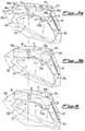
- in Figure 3a:
- a detail of the coupling lever at the instant corresponding to programming before reaching the dead point;
- in Figure 3b:
- a detail of the coupling lever at the instant of passing through the dead point of the half-revolution, actuation of the programming having already been performed;
- in Figure 4:
- a detail of the coupling lever in the case of an error in actuation of programming.
- As shown in Fig. 1a, the device according to this invention is composed of a rotary shaft 1, onto which are keyed, from the inside outwards, a
crank element 2 shaped so as to have anend 2a attached to the control rod 3 for the heddle frames, not illustrated here, and a substantially circular ring 2b, on which are mounted twopins 2c, opposite one another. - Coaxially and concentrically to said
crank 2 there is inserted a first bearing 4, to the inner ring of which is keyed an eccentric 5a, the upper part of which is shaped as a disc 5b having a much larger diameter and provided with a perforated, projectingflange 5c. - Onto this disc 5b there is also mounted, by a
rivet 6 or the like, abalancing lever 7, having shapedends - In more detail, the
end 8 is shaped, on the outer side, to aninclined cam profile 8a, whereas theend 9 has, on its outer side, a seconddifferent cam profile 10a, substantially of V-shape, which will be described in greater detail below, and also atooth 11 on the inside. - A
spring 12, disposed between saidflange 5c and saidend 9, exerts a biassing action on thelever 7 tending to cause it to rotate towards the centre of rotation of the shaft 1. - On said shaft there is, finally, keyed a
disc 13 having a diameter larger than the disc 5b and provided with twogrooves 13a and 13b, disposed diametrally opposite each other with respect to its centre of rotation. - With this arrangement, the
disc 13 is aligned with thelever 7 in such a manner that thetooth 11 can engage or not, as will be explained below, with one of the twonotches 13a or 13b. - Said rear V-
shaped profile 10 of theend 9 of the lever 7 (Figures 3a and 3b) is shaped at the front, considered in the direction of rotation indicated in the Figure, to a cam profile which is rounded to form aramp 10a, while at the rear it is shaped as a saw-tooth with an ascending front 10b followed, still in the same rotational direction, by a symmetrical, descendingfront 10c (Fig. 3a). - The dobby is complemented by a
control lever 14, of substantially C-shape, having its ends provided withprojecting profiles 14a and 14b and pivotal about apivot point 14c from a first position, determined by the thrust action of aspring 15 and astop element 16, to a second position, determined by the thrust action exerted by aprogramming actuator 17, the action of which is indicated schematically by two arrows A and B, respectively for forward and for backward movement. - The method of functioning of the dobby is as follows: at the start of the half-revolution (Fig. 1a), and on the assumption of forward motion and programming having been performed in the sense of varying the position of the frame, the
programmer 17 does not exert any action on thelever 14 which, under the action of thespring 15, is pushed into bearing against thestop element 16, in this manner leaving thebalance lever 7 free to rotate about itspin 6 under the biassing action of thespring 12, and as a consequence of this rotation thetooth 11 engages into thenotch 13a, thus making the disc 5b of the eccentric 5a integral with the rotatingdisc 13 which, by rotating with the shaft 1 during the half-revolution (Fig. 1b), entrains in rotation with itself the eccentric and therefore thecrank 2, which by rotating drives the control rod 3 of the frame, causing it to change position. - Before the half-revolution is completed (Figures 2a, 3a), the
programmer 17 arranges for actuation of the command relating to the next half-revolution, in the example of the present figure in the sense of keeping the frame in the preceding position, then exerts, by known means indicated schematically by arrow A, a pressure on thelever 14 which, by rotating about its pivot-point 14c, brings the tooth 14b into contact with therear surface 8a of theend 8 of thelever 7, said end, being shaped with an ascending front, thelever 7 is compelled, during the rotation of thedisc 13, to rotate about itsown pin 6, thus causing progressive disengagement of thetooth 11 from thenotch 13a. - The disengagement of the tooth causes the progressive engagement (Fig. 3a) of the
rear surface 10a of thelever 7 with thepin 2c, fixed to thecrank 2; the special cam shape of this surface allows it to roll around the pin without sliding, generating a coupling effect of theend 10 on thepin 2c, which in this way tends to entrain, firmly with itself, thelever 7 when this lever passes the dead-point of the half-revolution. - Once the dead-point of the half-revolution is reached (Fig. 3b) the lever is fully rotated outwards and engaged on the
pin 2c, and therefore thetooth 11 is entirely disengaged from the recess 13b, leaving the eccentric 5b free to rotate relative to thedisc 13 and therefore causing maintenance of the preceding position for the next half-revolution (Fig. 2b). - Figure 4 illustrates, in an enlarged detail, the positive safety action of the device according to the present invention; in fact, whenever the programming may have commanded disengagement of the
lever 7 from the disc 13 (that is maintenance of the position of the frame), but the actuation levers may not have correctly actuated this command, the lever, when it has passed the dead-point, will be situated with thetooth 11 only partly engaged with thenotch 13a, causing a situation of serious danger, if in fact the tooth had to disengage during the half-revolution it would cause the frame to drop during the work in progress, with serious consequences for the machine. - At this point, however, the second profile having an ascending front 10b of the rear surface of the
end 9 oflever 7 comes into contact with thepin 2c, which compels thelever 7 to rotate inwards, thus totally coupling thetooth 11 with thenotch 13a; in this manner the half-revolution is completed in normal operating conditions and even if the half-revolution will determine an incorrect stitch of the weft. - Numerous variants can be introduced in the shaping and relative arrangement of the cam profile of the rear surface of the coupling lever and the opposing pin, without thereby departing from the scope of the invention in its general characteristics.
Claims (5)
- Device for governing and controlling a rotary dobby for actuating heddle frames of looms of the type comprising a control shaft (1), a disc (13) keyed in rotation to said shaft, and an eccentric constituted of an eccentric ring (5a), also keyed to the shaft (1), with which it can rotate relative to an external translatory body (2) attached to the actuating rod (3) for the frames, the coupling between said disc (13) and said eccentric (5a) being effected by means of a lever (7) fixed to a disc (5b) of the eccentric (5a) and pivotal about its own pivot pin (6), characterized by the fact that said lever (7) has a rear surface (10) of the end (9) having a coupling tooth (11), this rear surface being shaped as a cam profile adapted for cooperating with corresponding, fixed opposition means, integral with the translatory element (2), said cam profile and said opposition means making possible a double positive action, for holding said end of the lever, in the case of disengagement of same from the disc for maintenance of the position of the frame, or for pressing on the lever for its complete re-engagement in the case of partial uncoupling, in this way guaranteeing that the movement sequence shall always be controlled.
- Device according to Claim 1, characterized by the fact that this cam profile has, in the rotational direction, a first front descending in the direction of rotation and a second ascending front, together forming a "V".
- Device according to Claim 1, characterized by the fact that said coupling and opposition means are preferably constituted of a pin fixed to the translatory element (3) in correspondence with the dead-points of rotation of the disc, said pins being able to rotate, or not rotate, about an axis perpendicular to the plane of said disc.
- Device according to Claim 1, characterized by the fact that said first front (10a) is curved so as to be able to roll around the pin (2c) and to create a coupling action onto it for holding the lever.
- Device according to Claim 1, characterized by the fact that said second front (10b) is inclined, so as to be able to receive the thrust action of the pin (2c) during the travel of the disc in the half-revolution and to determine its gradual, total re-entry into the notch (13a, 13b).
Applications Claiming Priority (2)
| Application Number | Priority Date | Filing Date | Title |
|---|---|---|---|
| IT02196890A IT1243890B (en) | 1990-11-05 | 1990-11-05 | DEVICE FOR THE COMMAND AND CONTROL OF A ROTARY DOBBY OF TEXTILE MACHINES WITH CAM PROFILE LEVER AND RELATIVE COOPERATING CONTRAST MEANS |
| IT2196890 | 1990-11-05 |
Publications (2)
| Publication Number | Publication Date |
|---|---|
| EP0485009A1 true EP0485009A1 (en) | 1992-05-13 |
| EP0485009B1 EP0485009B1 (en) | 1995-08-23 |
Family
ID=11189544
Family Applications (1)
| Application Number | Title | Priority Date | Filing Date |
|---|---|---|---|
| EP91202794A Expired - Lifetime EP0485009B1 (en) | 1990-11-05 | 1991-10-29 | Device for governing and controlling a rotary dobby of looms, having a profiled cam lever and associated cooperating opposition means |
Country Status (4)
| Country | Link |
|---|---|
| EP (1) | EP0485009B1 (en) |
| AT (1) | ATE126841T1 (en) |
| DE (1) | DE69112345T2 (en) |
| IT (1) | IT1243890B (en) |
Cited By (5)
| Publication number | Priority date | Publication date | Assignee | Title |
|---|---|---|---|---|
| EP0570628A1 (en) * | 1992-05-21 | 1993-11-24 | Stäubli AG (Stäubli SA) (Stäubli Ltd.) | Dobby containing an eccentric unit for the harness motions |
| EP0768402A1 (en) * | 1995-10-06 | 1997-04-16 | FIMTEXTILE S.p.A. | Device for programming rotary dobbies in weaving machines |
| EP0799919A1 (en) * | 1996-04-04 | 1997-10-08 | FIMTEXTILE S.p.A. | Device for carrying out the programming of rotary dobbies in weaving machines |
| EP0882821A1 (en) * | 1997-06-03 | 1998-12-09 | FIMTEXTILE S.p.A. | Programming device for rotary dobbies in weaving machines |
| EP1251194A1 (en) * | 2001-03-29 | 2002-10-23 | FIMTEXTILE S.p.A. | Improved programming device for rotary dobbies of weaving machines |
Citations (3)
| Publication number | Priority date | Publication date | Assignee | Title |
|---|---|---|---|---|
| EP0050160A1 (en) * | 1980-10-10 | 1982-04-28 | GebràDer Sulzer Aktiengesellschaft | Coupling system for operating the heald frames in a loom |
| FR2515702A1 (en) * | 1981-10-29 | 1983-05-06 | Staubli Sa Ets | IMPROVEMENTS ON ROTARY TRACKS |
| FR2596425A1 (en) * | 1986-03-26 | 1987-10-02 | Staubli Sa Ets | ROTARY RATIERE FOR WEAVING MACHINES |
-
1990
- 1990-11-05 IT IT02196890A patent/IT1243890B/en active IP Right Grant
-
1991
- 1991-10-29 AT AT91202794T patent/ATE126841T1/en not_active IP Right Cessation
- 1991-10-29 EP EP91202794A patent/EP0485009B1/en not_active Expired - Lifetime
- 1991-10-29 DE DE69112345T patent/DE69112345T2/en not_active Expired - Fee Related
Patent Citations (3)
| Publication number | Priority date | Publication date | Assignee | Title |
|---|---|---|---|---|
| EP0050160A1 (en) * | 1980-10-10 | 1982-04-28 | GebràDer Sulzer Aktiengesellschaft | Coupling system for operating the heald frames in a loom |
| FR2515702A1 (en) * | 1981-10-29 | 1983-05-06 | Staubli Sa Ets | IMPROVEMENTS ON ROTARY TRACKS |
| FR2596425A1 (en) * | 1986-03-26 | 1987-10-02 | Staubli Sa Ets | ROTARY RATIERE FOR WEAVING MACHINES |
Cited By (5)
| Publication number | Priority date | Publication date | Assignee | Title |
|---|---|---|---|---|
| EP0570628A1 (en) * | 1992-05-21 | 1993-11-24 | Stäubli AG (Stäubli SA) (Stäubli Ltd.) | Dobby containing an eccentric unit for the harness motions |
| EP0768402A1 (en) * | 1995-10-06 | 1997-04-16 | FIMTEXTILE S.p.A. | Device for programming rotary dobbies in weaving machines |
| EP0799919A1 (en) * | 1996-04-04 | 1997-10-08 | FIMTEXTILE S.p.A. | Device for carrying out the programming of rotary dobbies in weaving machines |
| EP0882821A1 (en) * | 1997-06-03 | 1998-12-09 | FIMTEXTILE S.p.A. | Programming device for rotary dobbies in weaving machines |
| EP1251194A1 (en) * | 2001-03-29 | 2002-10-23 | FIMTEXTILE S.p.A. | Improved programming device for rotary dobbies of weaving machines |
Also Published As
| Publication number | Publication date |
|---|---|
| IT9021968A0 (en) | 1990-11-05 |
| IT9021968A1 (en) | 1992-05-05 |
| DE69112345D1 (en) | 1995-09-28 |
| ATE126841T1 (en) | 1995-09-15 |
| EP0485009B1 (en) | 1995-08-23 |
| IT1243890B (en) | 1994-06-28 |
| DE69112345T2 (en) | 1996-04-18 |
Similar Documents
| Publication | Publication Date | Title |
|---|---|---|
| EP0485009B1 (en) | Device for governing and controlling a rotary dobby of looms, having a profiled cam lever and associated cooperating opposition means | |
| US4544000A (en) | Synchronized rotating dobby for weaving looms | |
| US3941161A (en) | Jacquard reversing mechanism for looms | |
| JPH0413458B2 (en) | ||
| EP0467444B1 (en) | Actuation device for the programming of rotary dobbies in looms | |
| EP0768402B1 (en) | Device for programming rotary dobbies in weaving machines | |
| EP0444726B1 (en) | Positive device for governing and controlling a rotary dobby in looms | |
| US4614211A (en) | Dobby | |
| EP0799919B1 (en) | Device for carrying out the programming of rotary dobbies in weaving machines | |
| US4781226A (en) | Driving and control mechanism for clamping, presentation and fastening of weft threads in gripper weaving looms | |
| EP1251194B1 (en) | Improved programming device for rotary dobbies of weaving machines | |
| EP1558799B1 (en) | Device for carrying out the programming of rotary dobbies in weaving machines | |
| EP0882821B1 (en) | Programming device for rotary dobbies in weaving machines | |
| EP1563131B1 (en) | Device for carrying out the programming of rotary dobbies in weaving machines | |
| KR0157423B1 (en) | Process for assembling the actuation element of a rotating dobby | |
| US5214834A (en) | Process for assembling the actuation elements of a rotating dobby | |
| EP0086999A1 (en) | Device for synchronizing the shedding device in a loom | |
| US4404993A (en) | Clutch arrangement for controlling a heddle of a weaving machine | |
| US4422480A (en) | Loom-heddle selector | |
| US4766936A (en) | Card switching apparatus for dobby | |
| US4351368A (en) | Dobby | |
| JPH0220223Y2 (en) | ||
| US203895A (en) | Improvement in looms | |
| EP1587975A1 (en) | Device to carry out the programming of rotary dobbies in weaving machines | |
| JPH0657576A (en) | Shedding mechanism for loom |
Legal Events
| Date | Code | Title | Description |
|---|---|---|---|
| PUAI | Public reference made under article 153(3) epc to a published international application that has entered the european phase |
Free format text: ORIGINAL CODE: 0009012 |
|
| AK | Designated contracting states |
Kind code of ref document: A1 Designated state(s): AT BE CH DE DK ES FR GB GR IT LI LU NL SE |
|
| 17P | Request for examination filed |
Effective date: 19920923 |
|
| 17Q | First examination report despatched |
Effective date: 19931223 |
|
| RAP1 | Party data changed (applicant data changed or rights of an application transferred) |
Owner name: BREVTEX SA |
|
| GRAA | (expected) grant |
Free format text: ORIGINAL CODE: 0009210 |
|
| AK | Designated contracting states |
Kind code of ref document: B1 Designated state(s): AT BE CH DE DK ES FR GB GR IT LI LU NL SE |
|
| PG25 | Lapsed in a contracting state [announced via postgrant information from national office to epo] |
Ref country code: GR Free format text: LAPSE BECAUSE OF FAILURE TO SUBMIT A TRANSLATION OF THE DESCRIPTION OR TO PAY THE FEE WITHIN THE PRESCRIBED TIME-LIMIT Effective date: 19950823 Ref country code: NL Free format text: LAPSE BECAUSE OF NON-PAYMENT OF DUE FEES Effective date: 19950823 Ref country code: AT Effective date: 19950823 Ref country code: DK Effective date: 19950823 Ref country code: ES Free format text: THE PATENT HAS BEEN ANNULLED BY A DECISION OF A NATIONAL AUTHORITY Effective date: 19950823 |
|
| REF | Corresponds to: |
Ref document number: 126841 Country of ref document: AT Date of ref document: 19950915 Kind code of ref document: T |
|
| REF | Corresponds to: |
Ref document number: 69112345 Country of ref document: DE Date of ref document: 19950928 |
|
| ET | Fr: translation filed | ||
| PG25 | Lapsed in a contracting state [announced via postgrant information from national office to epo] |
Ref country code: LU Free format text: LAPSE BECAUSE OF NON-PAYMENT OF DUE FEES Effective date: 19951031 |
|
| ITF | It: translation for a ep patent filed |
Owner name: STUDIO ING. ALFREDO RAIMONDI |
|
| PG25 | Lapsed in a contracting state [announced via postgrant information from national office to epo] |
Ref country code: GB Effective date: 19951123 Ref country code: SE Effective date: 19951123 |
|
| NLV1 | Nl: lapsed or annulled due to failure to fulfill the requirements of art. 29p and 29m of the patents act | ||
| PLBE | No opposition filed within time limit |
Free format text: ORIGINAL CODE: 0009261 |
|
| STAA | Information on the status of an ep patent application or granted ep patent |
Free format text: STATUS: NO OPPOSITION FILED WITHIN TIME LIMIT |
|
| GBPC | Gb: european patent ceased through non-payment of renewal fee |
Effective date: 19951123 |
|
| 26N | No opposition filed | ||
| REG | Reference to a national code |
Ref country code: CH Ref legal event code: PUE Owner name: FIMTEXTILE S.P.A. Free format text: BREVTEX S.A.##6534 SAN VITTORE (CH) -TRANSFER TO- FIMTEXTILE S.P.A.#VIA SPIAZZI 52#24028 PONTE NOSSA (IT) |
|
| REG | Reference to a national code |
Ref country code: FR Ref legal event code: TP |
|
| PGFP | Annual fee paid to national office [announced via postgrant information from national office to epo] |
Ref country code: CH Payment date: 20080923 Year of fee payment: 18 |
|
| PGFP | Annual fee paid to national office [announced via postgrant information from national office to epo] |
Ref country code: IT Payment date: 20080909 Year of fee payment: 18 |
|
| PGFP | Annual fee paid to national office [announced via postgrant information from national office to epo] |
Ref country code: DE Payment date: 20081030 Year of fee payment: 18 |
|
| PGFP | Annual fee paid to national office [announced via postgrant information from national office to epo] |
Ref country code: BE Payment date: 20080929 Year of fee payment: 18 |
|
| PGFP | Annual fee paid to national office [announced via postgrant information from national office to epo] |
Ref country code: FR Payment date: 20081027 Year of fee payment: 18 |
|
| BERE | Be: lapsed |
Owner name: *FIMTEXTILE S.P.A. Effective date: 20091031 |
|
| REG | Reference to a national code |
Ref country code: CH Ref legal event code: PL |
|
| REG | Reference to a national code |
Ref country code: FR Ref legal event code: ST Effective date: 20100630 |
|
| PG25 | Lapsed in a contracting state [announced via postgrant information from national office to epo] |
Ref country code: DE Free format text: LAPSE BECAUSE OF NON-PAYMENT OF DUE FEES Effective date: 20100501 Ref country code: FR Free format text: LAPSE BECAUSE OF NON-PAYMENT OF DUE FEES Effective date: 20091102 |
|
| PG25 | Lapsed in a contracting state [announced via postgrant information from national office to epo] |
Ref country code: BE Free format text: LAPSE BECAUSE OF NON-PAYMENT OF DUE FEES Effective date: 20091031 Ref country code: LI Free format text: LAPSE BECAUSE OF NON-PAYMENT OF DUE FEES Effective date: 20091031 Ref country code: CH Free format text: LAPSE BECAUSE OF NON-PAYMENT OF DUE FEES Effective date: 20091031 |
|
| PG25 | Lapsed in a contracting state [announced via postgrant information from national office to epo] |
Ref country code: IT Free format text: LAPSE BECAUSE OF NON-PAYMENT OF DUE FEES Effective date: 20091029 |