EP0484781A2 - Slab upsetting press for hot wide strip rolling mills - Google Patents
Slab upsetting press for hot wide strip rolling mills Download PDFInfo
- Publication number
- EP0484781A2 EP0484781A2 EP91118341A EP91118341A EP0484781A2 EP 0484781 A2 EP0484781 A2 EP 0484781A2 EP 91118341 A EP91118341 A EP 91118341A EP 91118341 A EP91118341 A EP 91118341A EP 0484781 A2 EP0484781 A2 EP 0484781A2
- Authority
- EP
- European Patent Office
- Prior art keywords
- plate
- longitudinal
- press
- bearing
- foundation
- Prior art date
- Legal status (The legal status is an assumption and is not a legal conclusion. Google has not performed a legal analysis and makes no representation as to the accuracy of the status listed.)
- Granted
Links
- 238000005096 rolling process Methods 0.000 title claims abstract description 6
- 238000007667 floating Methods 0.000 claims abstract description 21
- 239000002184 metal Substances 0.000 claims description 24
- 210000000078 claw Anatomy 0.000 claims description 21
- 229920001343 polytetrafluoroethylene Polymers 0.000 claims description 10
- 239000004810 polytetrafluoroethylene Substances 0.000 claims description 10
- 239000004033 plastic Substances 0.000 claims description 5
- 239000000969 carrier Substances 0.000 claims description 3
- 239000000314 lubricant Substances 0.000 claims description 3
- -1 polytetrafluoroethylene Polymers 0.000 claims description 3
- 229910001220 stainless steel Inorganic materials 0.000 claims description 3
- 239000010935 stainless steel Substances 0.000 claims description 3
- 230000006835 compression Effects 0.000 description 9
- 238000007906 compression Methods 0.000 description 9
- 238000010276 construction Methods 0.000 description 4
- 150000001875 compounds Chemical class 0.000 description 2
- 230000007797 corrosion Effects 0.000 description 2
- 238000005260 corrosion Methods 0.000 description 2
- 238000000034 method Methods 0.000 description 2
- 238000004873 anchoring Methods 0.000 description 1
- 230000005540 biological transmission Effects 0.000 description 1
- 230000015572 biosynthetic process Effects 0.000 description 1
- 238000005553 drilling Methods 0.000 description 1
- 230000000694 effects Effects 0.000 description 1
- 238000005516 engineering process Methods 0.000 description 1
- 238000005098 hot rolling Methods 0.000 description 1
- 238000007789 sealing Methods 0.000 description 1
Images


Classifications
-
- B—PERFORMING OPERATIONS; TRANSPORTING
- B21—MECHANICAL METAL-WORKING WITHOUT ESSENTIALLY REMOVING MATERIAL; PUNCHING METAL
- B21B—ROLLING OF METAL
- B21B15/00—Arrangements for performing additional metal-working operations specially combined with or arranged in, or specially adapted for use in connection with, metal-rolling mills
-
- B—PERFORMING OPERATIONS; TRANSPORTING
- B21—MECHANICAL METAL-WORKING WITHOUT ESSENTIALLY REMOVING MATERIAL; PUNCHING METAL
- B21J—FORGING; HAMMERING; PRESSING METAL; RIVETING; FORGE FURNACES
- B21J1/00—Preparing metal stock or similar ancillary operations prior, during or post forging, e.g. heating or cooling
- B21J1/04—Shaping in the rough solely by forging or pressing
-
- B—PERFORMING OPERATIONS; TRANSPORTING
- B21—MECHANICAL METAL-WORKING WITHOUT ESSENTIALLY REMOVING MATERIAL; PUNCHING METAL
- B21B—ROLLING OF METAL
- B21B15/00—Arrangements for performing additional metal-working operations specially combined with or arranged in, or specially adapted for use in connection with, metal-rolling mills
- B21B15/0035—Forging or pressing devices as units
-
- B—PERFORMING OPERATIONS; TRANSPORTING
- B21—MECHANICAL METAL-WORKING WITHOUT ESSENTIALLY REMOVING MATERIAL; PUNCHING METAL
- B21J—FORGING; HAMMERING; PRESSING METAL; RIVETING; FORGE FURNACES
- B21J13/00—Details of machines for forging, pressing, or hammering
- B21J13/04—Frames; Guides
Definitions
- the invention relates to an upsetting press for the reduction of rolling stock, in particular the slab width in hot broad strip roughing mills, with tool carriers accommodating pressing tools arranged on both sides of the slab edge, which can be moved in the direction of the slab reduction by a crank mechanism arranged in a crankcase.
- pressing tools which are received by tool carriers, are arranged on both sides of the slab edge in order to reduce the width of slabs in a hot wide strip roughing mill.
- each pressing tool with the associated tool carrier is moved with the aid of a steering system actuated by a crank mechanism in the direction of reducing the width of the slab, the crank mechanism being arranged in a crankcase.
- the crank mechanism consists of two driven eccentric shafts; A connecting rod is mounted on each eccentric shaft; the connecting rod head is connected to the tool carrier for transmitting the compression forces.
- a feed drive acting essentially in the direction of the slab feed acts on the tool carrier.
- This upsetting press enables the width of the slab to be continuously reduced to values specified by rolling technology. Upsetting presses of this size can reduce a slab with a width of approx. 2100 mm and a thickness of approx. 265 mm by up to 300 mm in just one pass. As a result of the large compression forces of up to 30 MN and under the influence of heat, the horizontal compression structure must be able to stretch without exerting forces on the foundation. Furthermore, the crankcase, from which the pressing forces are introduced into the slab, must not move in its guide play during the pressing process, so that a desired width tolerance of the reduced slab with high edge quality can also be guaranteed in continuous operation.
- the object of the invention is to construct the compression press according to the preamble of claim 1 in such a way that the action of the pressing forces, in particular also the inertial forces and the action of heat on the compression frame and on the crankcase do not damage the press and do not reduce it the quality of the compressed slab, for example the edge quality, and that a predetermined width tolerance of the compressed slab can be guaranteed.
- This object is achieved in the compression press mentioned at the outset with the characterizing features of claim 1.
- the features of the following claims 2 to 10 serve the further configuration of the upsetting press.
- each lower upright longitudinal spar of the compression press facing the press foundation has a fixed base bearing approximately in the center and at least two on the longitudinal side Has floating bearing, and that the crankcase between the upper and lower stator longitudinal bars can be locked with the help of releasable clamping devices.
- the pressing forces generated during the pressing and the resulting mass forces as a result of the moving masses are initially absorbed by the crankcase firmly clamped in the scaffold stand, passed into the longitudinal column spars and absorbed by them.
- possible longitudinal strains of the uprights caused by the pressing forces can be intercepted by several floating bearings. In this way, thermal expansions during hot operation of the upsetting press can be absorbed in such a way that the lateral upsetting of the slabs leads to consistently good upsetting results.
- each lower upright longitudinal spar has lateral claws approximately in the spar center and is supported on a fitting plate in a bearing plate connected to the foundation with the spar leading side plates, that the lateral claws engage in the side plates and that the Claws can be clamped to the bearing plate using connecting elements - preferably with screw connections.
- the side of the lower upright longitudinal strut facing the foundation in this area has a metal pressure plate, that in this area an opposite side with the foundation connected bearing plate has a metal pressure plate, and that between the metal pressure plates, a rustproof, polished metal plate and a slide plate made of plastic with cavities arranged on the sliding surface with lubricant-fillable cavities - preferably made of polytetrafluoroethylene (PTFE) - are arranged, each in one of the metal pressure plates are inserted.
- PTFE polytetrafluoroethylene
- the cavities arranged on the upper sliding surface of the PTFE sliding plate with a lubricant are particularly advantageous. As a result, the effect of the so-called micro friction between the sliding surfaces of such a support can be significantly reduced.
- the metal pressure plates are made of stainless steel, which are glued and screwed to the spar or to the bearing plate. The measures on the scaffolding stand of the upsetting press are largely protected against corrosion by these measures. It is also advantageous if the screw heads embedded in the pressure plates are chambered with a sealing filling compound before the polished metal plate or the PTFE sliding plate are inserted into the pressure plates.
- the floating bearing connected to the bearing plate which has the longitudinal strut leading side plates, that standing bushes are arranged in bores of lateral claws of the longitudinal struts, which stand up on the bearing plate and the other end of which is a short distance above the claw has a counter plate that on the counter plate a screw connection reaching into the bearing plate or into the foundation is supported and that between the claws and the side plates sliding plates are arranged against each other.
- the clamping devices for the crankcase are hydraulic clamping cylinders which can be adjusted depending on the pressing forces so that the crankcase does not move back and forth in its guide play during the pressing process. It is expedient here if the hydraulic clamping cylinders are located on each upper longitudinal side of the crankcase, opposite the underside of the upper longitudinal stile and are arranged between a guide rail fastened to the crankcase, spanning the lower longitudinal stalk and the outside of each lower longitudinal stile. The crankcase is laterally clamped by the two hydraulic clamping cylinders and pressed by the four hydraulic clamping cylinders onto the two lower longitudinal pillars.
- a sliding plate is advantageously arranged between the clamping cylinder and the respective clamping surface, and it is further provided that the crankcase is on the the lower upright longitudinal spars by means of sliding plates so that the consequences of wear from the constant micro friction between the clamping cylinder and the clamping surface remain as small as possible.
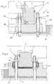
- the side view of the upsetting press 1, shown partially in section in FIG. 1, shows a horizontal scaffold stand 2 with two lower uprights 3 and two upper uprights 4 and cross members 5 which connect the uprights to one another.
- a crankcase 7 is arranged on both sides of a longitudinal slab 3, 4 on both sides of a slab 6 to be reduced in width, which has a mechanical adjustment and a not shown Balancing device 8 is supported on the crossbar 5 of the scaffold stand.
- Two eccentric shafts 9 with pressure connecting rods 10 are mounted in the crankcase 7.
- the connecting rod heads 11 are connected to a tool carrier 12 for the pressing tools 13. With the help of the pressing tools 13 and with the help of the pressing forces emanating from the crank drive, the slab 6, which is transported by driving rollers 14 through the upsetting press, is reduced in width.
- the pressing forces are transmitted to the eccentric shafts by a motor and transmission arrangement 15 with the aid of cardan shafts 16.
- the lower uprights 3 are supported several times on the foundation 17.
- support is provided with the aid of a fixed bearing 18, followed on both sides of the stand by a floating bearing 19 with lateral guidance, a floating bearing 20 without lateral guidance and a floating bearing 19 with lateral guidance.
- releasable tensioning device 21 are arranged between the lower upright side members 3 and the upper upright side members 4.
- Fig. 2 shows a bearing plate 22 connected to the foundation 17 for the central fixed bearing 18 and two adjacent floating bearings 19 with side guides for the two lower longitudinal pillars 3.
- the longitudinal section along the line III-III in Fig. 2 shows in Fig. 3 that for the purpose of forming the fixed bearing 18, each lower upright longitudinal spar has lateral claws 23 approximately in the middle of the spar, and that it is supported on a fitting plate 24 on the bearing plate 22 connected to the foundation 17 with two lateral side plates 25 leading the spar.
- the lateral claws 23 of the longitudinal longitudinal spar engage in the side plates 25 and the claws 23 are firmly clamped to the bearing plate 22 by means of the screw connections 26.
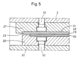
- the longitudinal section along the line IV-IV in Fig. 2 shows in Fig.
- the polished metal plate and the PTFE slide plate are each inserted in one of the metal pressure plates 27, 28.
- the metal pressure plates 27, 28 are made of stainless steel and are glued to the lower upright longitudinal bar 4 or to the bearing plate 22 and, as shown in FIG. 5, screwed to the bar or to the bearing plate with screws 32.
- the screw head countersunk in the pressure plates 27, 28 is additionally chambered with a filling compound, so that possible corrosion at the connection points of the bearing elements is excluded as far as possible. It can be seen that Fig. 5 shows the bearing elements of a non-locating bearing without side guide for the longitudinal pillar.
- the floating bearing shown there with a side guide has two side plates 33 connected to the bearing plate 22 and guiding the longitudinal column 4 and also lateral claws of the longitudinal columns in which holes 35 for so-called standing bushes 36 are arranged.
- These standing bushes stand on the bearing plate 22 and have a counter plate 37 at their other end at a short distance above the lateral claws 34.
- a screw connection 38 reaching into the bearing plate 22 or into the foundation 17 is supported on the counter plate 37.
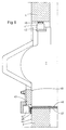
- crankcase 7 shows, based on a partial section, the crankcase 7 as well as the lower longitudinal stile 3 and the upper longitudinal stile 4.
- the crankcase is locked by means of releasable clamping devices 21 between the upper and the lower longitudinal stile.
- These clamping devices are hydraulic clamping cylinders 41. These are located on each upper longitudinal side 42 of the crankcase 7, opposite the underside of the upper longitudinal column 4.
- a guide rail 43 which extends across the lower stator longitudinal bar 3 is arranged laterally on the outside 49.
- the hydraulic clamping cylinder 41 is arranged between this guide rail and the outside 44 of the lower longitudinal column.
- a sliding plate 45 is arranged between the respective clamping cylinder 41 and the clamping surface interacting therewith.
- the crankcase 7 lies on the lower longitudinal stile 3 by means of a pair of sliding plates 46, 47 on. With the help of the sliding plates 45, 46, 47, possible wear, which can be attributed to constant micro-friction, is largely avoided.
Abstract
Description
Die Erfindung betrifft eine Stauchpresse zur Reduktion von Walzgut, insbesondere der Brammenbreite in Warmbreitband-Vorstraßen mit beidseitig zur Brammenkante angeordneten Preßwerkzeuge aufnehmenden Werkzeugträgern, die von einem in einem Kurbelgehäuse angeordneten Kurbeltrieb in Richtung der Brammenrduktion bewegbar sind.The invention relates to an upsetting press for the reduction of rolling stock, in particular the slab width in hot broad strip roughing mills, with tool carriers accommodating pressing tools arranged on both sides of the slab edge, which can be moved in the direction of the slab reduction by a crank mechanism arranged in a crankcase.
Bei einer Stauchpresse gemäß der älteren deutschen Patentanmeldung P 39 17 398.4 sind zur Reduktion der Breite von Brammen in einer Warmbreitband-Vorstraße zu beiden Seiten der Brammenkante Preßwerkzeuge angeordnet, die von Werkzeugträgern aufgenommen sind. Zur Ausbildung eines Reduktionsantriebes wird jedes Preßwerkzeug mit dem zugehörigen Werkzeugträger mit Hilfe eines von einem Kurbeltrieb betätigten Lenkersystems in Richtung der Breitenreduktion der Bramme bewegt, wobei der Kurbeltrieb in einem Kurbelgehäuse angeordnet ist. Der Kurbeltrieb besteht aus zwei angetriebenen Exzenterwellen; auf jeder Exzenterwelle ist ein Pleuel gelagert; dessen Pleuelkopf steht mit dem Werkzeugträger zur Übertragung der Stauchkräfte in Verbindung. Am Werkzeugträger greift ein im wesentlichen in Richtung des Brammenvorschubs wirkender Vorschubantrieb an. Durch diese Maßnahmen wird der Bewegungsablauf der Preßwerkzeuge für das reduzierende Pressen und für das Vorschieben der Preßwerkzeuge voneinander getrennt steuerbar, so daß für jede beliebige Vorschubgröße eine Synchronisation der Bewegung der Preßwerkzeuge mit der Bewegung der seitlich zu pressenden Bramme gewährleistet ist. Diese Stauchpresse ermöglicht die kontinuierliche Reduktion der Breite der Bramme auf walztechnisch vorgegebene Werte. Stauchpressen dieser Größenordnung können in nur einem Durchgang eine Bramme mit ca. 2100 mm Breite und einer Dicke von ca. 265 mm um bis zu 300 mm reduzieren. Infolge der großen Stauchpreßkräfte bis zu 30 MN und unter Einwirkung von Wärme muß sich das liegende Stauchgerüst dehnen können, ohne daß Kräfte auf das Fundament ausgeübt werden. Ferner darf sich das Kurbelgehäuse, von dem die Preßkräfte in die Bramme eingeleitet werden, während des Preßvorganges in seinem Führungsspiel nicht bewegen, damit eine gewünschte Breitentoleranz der reduzierten Bramme bei hoher Kantenqualität auch im Dauerbetrieb gewährleistet werden kann.In an upsetting press according to the older German
Die Aufgabe der Erfindung besteht darin, die Stauchpresse gemäß Oberbegriff des Anspruchs 1 konstruktiv so zu gestalten, daß die Einwirkung der Preßkräfte, insbesondere auch der Massenkräfte und die Einwirkung von Wärme auf das Stauchgerüst und auf das Kurbelgehäuse zu keiner Beschädigung der Presse und zu keiner Minderung der Qualität der gestauchten Bramme bspw. der Kantenqualität führt und daß eine vorgegebene Breitentoleranz der gestauchten Bramme gewährleistet werden kann. Diese Aufgabe wird bei der eingangs genannten Stauchpresse mit den kennzeichnenden Merkmalen des Anspruchs 1 gelöst. Die Merkmale der nachfolgenden Patentansprüche 2 bis 10 dienen der weiteren Ausgestaltung der Stauchpresse.The object of the invention is to construct the compression press according to the preamble of claim 1 in such a way that the action of the pressing forces, in particular also the inertial forces and the action of heat on the compression frame and on the crankcase do not damage the press and do not reduce it the quality of the compressed slab, for example the edge quality, and that a predetermined width tolerance of the compressed slab can be guaranteed. This object is achieved in the compression press mentioned at the outset with the characterizing features of claim 1. The features of the following
Nach Anspruch 1 zeichnet sich die genannte Stauchpresse dadurch aus, daß jeder dem Pressenfundament zugewandte untere Ständerlängsholm der Stauchpresse etwa mittig ein Fundamentfestlager und längsseitig mindestens zwei Loslager aufweist, und daß das Kurbelgehäuse zwischen den oberen und unteren Ständerlängsholmen mit Hilfe von lösbaren Spannvorrichtungen arretierbar ist. Die beim Pressen entstehenden Preßkräfte sowie die infolge der bewegten Massen resultierenden Massenkrääfte werden zunächst von dem im Gerüstständer fest eingespannten Kurbelgehäuse aufgenommen, in die Ständerlängsholme geleitet und von diesen aufgenommen. Ausgehend von dem mittigen Festlager können mögliche von den Preßkräften verursachte Längsdehnungen der Ständerholme von mehreren Loslagern abgefangen werden. Auf diese Weise können auch Wärmedehnungen während des heißen Betriebes der Stauchpresse so aufgefangen werden, daß das seitliche Stauchen der Brammen zu gleichbleibend guten Stauchergebnissen führt.According to claim 1, the above-mentioned compression press is characterized in that each lower upright longitudinal spar of the compression press facing the press foundation has a fixed base bearing approximately in the center and at least two on the longitudinal side Has floating bearing, and that the crankcase between the upper and lower stator longitudinal bars can be locked with the help of releasable clamping devices. The pressing forces generated during the pressing and the resulting mass forces as a result of the moving masses are initially absorbed by the crankcase firmly clamped in the scaffold stand, passed into the longitudinal column spars and absorbed by them. Starting from the central fixed bearing, possible longitudinal strains of the uprights caused by the pressing forces can be intercepted by several floating bearings. In this way, thermal expansions during hot operation of the upsetting press can be absorbed in such a way that the lateral upsetting of the slabs leads to consistently good upsetting results.
Zur Ausbildung des Festlagers der Stauchpresse ist vorgesehen, daß jeder untere Ständerlängsholm etwa in der Holmmitte seitliche Pratzen aufweist und auf einer Paßplatte in einer mit dem Fundament verbundenen Lagerplatte mit den Holm führenden Seitenplatten abgestützt ist, daß die seitlichen Pratzen in die Seitenplatten eingreifen und daß die Pratzen mittels Verbindungselementen - vorzugsweise mit Schraubverbindungen - mit der Lagerplatte verspannbar sind. Mit Hilfe dieser Konstruktionselemente wird eine sehr robuste Bauweise für das Festlager der Stauchpresse erreicht und es wird eine sehr sichere und ortsfeste Verankerung dieser schweren Maschine auf dem Fundament in der Mitte der Walzlinie der übrigen Warmwalzgerüste gewährleistet.To form the fixed bearing of the upsetting press, it is provided that each lower upright longitudinal spar has lateral claws approximately in the spar center and is supported on a fitting plate in a bearing plate connected to the foundation with the spar leading side plates, that the lateral claws engage in the side plates and that the Claws can be clamped to the bearing plate using connecting elements - preferably with screw connections. With the help of these construction elements, a very robust construction for the fixed bearing of the upsetting press is achieved and a very safe and fixed anchoring of this heavy machine on the foundation in the middle of the rolling line of the other hot rolling stands is guaranteed.
Zur Ausbildung des Loslagers der Stauchpresse wird gemäß der Erfindung vorgeschlagen, daß die in diesem Bereich dem Fundament zugewandte Seite des unteren Ständerlängsholms eine metallene Druckplatte aufweist, daß eine in diesem Bereich gegenüberliegende mit dem Fundament verbundene Lagerplatte eine metallene Druckplatte aufweist, und daß zwischen den metallenen Druckplatten eine rostfreie, polierte Metallplatte sowie eine Gleitplatte aus Kunststoff mit auf der Gleitfläche angeordneten mit Schmiermittel ausfüllbaren Höhlungen - vorzugsweise aus Polytetrafluoräthylen (PTFE) - angeordnet ist, die jeweils in einer der metallenen Druckplatten eingefügt sind. Die Konstruktion von diesen losen Auflagern genügt höchsten Beanspruchungen, insbesondere vermindert die PTFE-Gleitplatte die Widerstände einer Gleitreibung ganz erheblich. Von besonderem Vorteil sind die auf der oberen Gleitfläche der PTFE-Gleitplatte angeordneten Höhlungen mit einem Schmiermittel. Hierdurch kann die Auswirkung der sogenannten Mikroreibung zwischen den Gleitflächen eines solchen Auflagers ganz bedeutsam vermindert werden. Zur Ausgestaltung eines solchen losen Auflagers ist weiter vorgeschlagen, daß die metallenen Druckplatten aus rostfreiem Stahl bestehen, die mit dem Holm bzw. mit der Lagerplatte verklebt und verschraubt sind. Die Auflager des Gerüstständers der Stauchpresse sind durch diese Maßnahmen weitgehend gegen Korrosion geschützt. Vorteilhaft ist ferner, wenn die in den Druckplatten eingelassenen Schraubenköpfe mit einer dichtenden Ausfüllmasse gekammert werden, bevor die polierte Metallplatte bzw. die PTFE-Gleitplatte in die Druckplatten eingefügt werden.To form the floating bearing of the upsetting press, it is proposed according to the invention that the side of the lower upright longitudinal strut facing the foundation in this area has a metal pressure plate, that in this area an opposite side with the foundation connected bearing plate has a metal pressure plate, and that between the metal pressure plates, a rustproof, polished metal plate and a slide plate made of plastic with cavities arranged on the sliding surface with lubricant-fillable cavities - preferably made of polytetrafluoroethylene (PTFE) - are arranged, each in one of the metal pressure plates are inserted. The construction of these loose supports meets the highest demands, in particular the PTFE sliding plate significantly reduces the resistance to sliding friction. The cavities arranged on the upper sliding surface of the PTFE sliding plate with a lubricant are particularly advantageous. As a result, the effect of the so-called micro friction between the sliding surfaces of such a support can be significantly reduced. To design such a loose support it is further proposed that the metal pressure plates are made of stainless steel, which are glued and screwed to the spar or to the bearing plate. The measures on the scaffolding stand of the upsetting press are largely protected against corrosion by these measures. It is also advantageous if the screw heads embedded in the pressure plates are chambered with a sealing filling compound before the polished metal plate or the PTFE sliding plate are inserted into the pressure plates.
Zur Ausbildung eines losen Auflagers mit Seitenführung wird eregänzend vorgeschlagen, daß das Loslager mit der Lagerplatte verbundene, den Ständerlängsholm führende Seitenplatten aufweist, daß in Bohrungen von seitlichen Pratzen der Ständerlängsholme Stehbüchsen angeordnet sind, die auf der Lagerplatte aufstehen und deren anderes Ende mit geringem Abstand oberhalb der Pratzen eine Gegenplatte aufweist, daß an der Gegenplatte eine in die Lagerplatte bzw. in das Fundament reichende Schraubverbindung abgestützt ist und daß zwischen den Pratzen und den Seitenplatten gegeneinander gleitende Paßplatten angeordnet sind. Mit diesen Maßnahmen wird gewährleistet, daß der Ständerholm in Längsrichtung dehnfähig bleibt, gleichwohl aber eine sichere Seitenführung erhält. Infolge der Anordnung der Stehbüchse gehen sämtliche Verspannungskräfte von der Schraubverbindung direkt in die Lagerplatte. Zur mehrfachen Abstützung des Gerüstständers auf dem Fundament wird weiterhin eine vom Festlager nach beiden Seiten ausgehende Folge von Loslagern mit bzw. ohne Seitenführung des Ständerlängsholms vorgeschlagen.To form a loose support with side guides, it is additionally proposed that the floating bearing connected to the bearing plate, which has the longitudinal strut leading side plates, that standing bushes are arranged in bores of lateral claws of the longitudinal struts, which stand up on the bearing plate and the other end of which is a short distance above the claw has a counter plate that on the counter plate a screw connection reaching into the bearing plate or into the foundation is supported and that between the claws and the side plates sliding plates are arranged against each other. With these measures it is ensured that the upright remains stretchable in the longitudinal direction, but nevertheless receives a safe lateral guidance. As a result of the arrangement of the standing bushing, all tensioning forces go directly from the screw connection into the bearing plate. For multiple support of the scaffold stand on the foundation, a sequence of floating bearings, with or without lateral guidance of the longitudinal column spar, which extends from the fixed bearing to both sides, is also proposed.
Zur einwandfreien Festlegung des Kurbelgehäuses innerhalb der Stauchpresse wird weiter ausgestaltend vorgeschlagen, daß die Spannvorrichtungen für das Kurbelgehäuse hydraulische Klemmzylinder sind, die in Abhängigkeit der Preßkräfte so eingestellt werden können, daß das Kurbelgehäuse sich während des Preßvorganges in seinem Führungsspiel nicht hin- und herbewegt. Zweckmäßig ist hierbei, wenn sich die hydraulischen Klemmzylinder auf jeder oberen Längsseite des Kurbelgehäuses, der Unterseite des oberen Ständerlängsholmes gegenüberliegend befinden sowie zwischen einer am Kurbelgehäuse befestigten, den unteren Ständerlängsholm mit Abstand übergreifenden Führungsschiene und der Außenseite jedes unteren Ständerlängsholmes angeordnet sind. Das Kurbelgehäuse wird durch die zwei hydraulischen Klemmzylinder seitlich geklemmt und durch die vier hydraulischen Klemmzylinder auf die beiden unteren Ständerlängsholme gepreßt.For proper fixing of the crankcase within the upsetting press, it is further proposed that the clamping devices for the crankcase are hydraulic clamping cylinders which can be adjusted depending on the pressing forces so that the crankcase does not move back and forth in its guide play during the pressing process. It is expedient here if the hydraulic clamping cylinders are located on each upper longitudinal side of the crankcase, opposite the underside of the upper longitudinal stile and are arranged between a guide rail fastened to the crankcase, spanning the lower longitudinal stalk and the outside of each lower longitudinal stile. The crankcase is laterally clamped by the two hydraulic clamping cylinders and pressed by the four hydraulic clamping cylinders onto the two lower longitudinal pillars.
Bei der lösbaren Spannvorrichtung für das Kurbelgehäuse sind vorteilhafterweise zwischen Klemmzylinder und jeweiliger Klemmfläche eine Gleitplatte angeordnet und ferner ist vorgesehen, daß das Kurbelgehäuse auf den unteren Ständerlängsholmen mittels Gleitplatten aufliegt, damit der Verschleißfolgen der ständigen Mikroreibung zwischen Klemmzylinder und Klemmfläche möglichst gering bleibt.In the releasable clamping device for the crankcase, a sliding plate is advantageously arranged between the clamping cylinder and the respective clamping surface, and it is further provided that the crankcase is on the the lower upright longitudinal spars by means of sliding plates so that the consequences of wear from the constant micro friction between the clamping cylinder and the clamping surface remain as small as possible.
Die Erfindung wird nachfolgend näher beschrieben. Es zeigen
- Figur 1
- die Seitenansicht der Stauchpresse mit dem liegenden, mehrfach auf dem Fundament abgestützten Gerüstständer,
Figur 2- die mittlere Lagerplatte des Gerüstständers mit Festlager und Loslager,
Figur 3- einen Schnitt durch das Festlager entlang der Linie III-III in Fig. 2,
- Figur 4
- einen Schnitt durch das Loslager mit Seitenführung entlang der Linie IV-IV in Fig. 2,
Figur 5- einen Schnitt durch das Loslager ohne Seitenführung,
Figur 6- einen Teilausschnitt des zwischen den Ständerlängsholmen eingespannten Kurbelgehäuses.
- Figure 1
- the side view of the upsetting press with the scaffold stand lying on it, supported several times on the foundation,
- Figure 2
- the middle bearing plate of the scaffold stand with fixed bearing and floating bearing,
- Figure 3
- a section through the fixed bearing along the line III-III in Fig. 2,
- Figure 4
- 3 shows a section through the floating bearing with lateral guidance along the line IV-IV in FIG. 2,
- Figure 5
- a section through the floating bearing without lateral guidance,
- Figure 6
- a partial section of the crankcase clamped between the longitudinal stiles.
Die in Fig. 1 teilweise im Schnitt dargestellte Seitenansicht der Stauchpresse 1 zeigt einen liegenden Gerüstständer 2 mit zwei unteren Ständerlängsholmen 3 und zwei oberen Ständerlängsholmen 4 sowie Quertraversen 5, welche die Ständerlängsholme untereinander verbinden. Zwischen den Ständerlängsholmen 3, 4 ist zu beiden Seiten einer in der Breite zu reduzierenden Bramme 6 ein Kurbelgehäuse 7 angeordnet, welches von einer nicht näher dargestellten mechanischen Anstellung und einer Ausbalanciervorrichtung 8 an der Quertraverse 5 des Gerüstständers abgestützt ist. In dem Kurbelgehäuse 7 sind zwei Exzenterwellen 9 mit Druckpleueln 10 gelagert. Die Pleuelköpfe 11 sind mit einem Werkzeugträger 12 für die Preßwerkzeuge 13 verbunden. Mit Hilfe der Preßwerkzeuge 13 und mit Hilfe der von dem Kurbeltrieb ausgehenden Preßkräfte wird die Bramme 6, die von Treiberrollen 14 durch die Stauchpresse transportiert wird, in der Breite reduziert. Die Preßkräfte werden auf die Exzenterwellen von einer Motor- und Getriebeanordnung 15 mit Hilfe von Gelenkwellen 16 übertragen. Die unteren Ständerlängsholme 3 stützen sich mehrfach auf dem Fundament 17 ab. Im Mittenbereich der Stauchpresse erfolgt die Abstützung mit Hilfe eines Festlagers 18, nach beiden Ständerseiten gefolgt von einem Loslager 19 mit Seitenführung, einem Loslager 20 ohne Seitenführung und einem Loslager 19 mit Seitenführung. Zur Abstützung und Arretierung des Kurbelgehäuses 7 im Gerüstständer 2 sind zwischen den unteren Ständerlängsholmen 3 und den oberen Ständerlängsholmen 4 lösbare Spannvorrichtung 21 angeordnet. Die vorgeschlagene Abstützung der Stauchpresse auf dem Fundament sowie die gewählte Arretierung des Kurbelgehäuses in der Stauchpresse ermöglichen es, daß sich die Ständer unter der Einwirkung von Preßkraft und Wärme in Richtung der Preßkräfte frei dehnen können, ohne daß Kräfte auf das Fundament ausgeübt werden. Die hierzu erforderliche Konstruktion von Festlager, Loslager und Arretierung wird nachfolgend näher beschrieben.The side view of the upsetting press 1, shown partially in section in FIG. 1, shows a
Fig. 2 zeigt eine mit dem Fundament 17 verbundene Lagerplatte 22 für das mittige Festlager 18 und zwei nebengeordnete Loslager 19 mit Seitenführung für die beiden unteren Ständerlängsholme 3. Der Längsschnitt entlang der Linie III-III in Fig. 2 zeigt in Fig. 3, daß zwecks Ausbildung des Festlagers 18 jeder untere Ständerlängsholm etwa in der Holmmitte seitliche Pratzen 23 aufweist, und daß er auf einer Paßplatte 24 auf der mit dem Fundament 17 verbundenen Lagerplatte 22 mit zwei seitlichen, den Holm führenden Seitenplatten 25 abgestützt ist. Die seitlichen Pratzen 23 des Ständerlängsholms greifen in die Seitenplatten 25 ein und die Pratzen 23 sind mit Hilfe der Schraubverbindungen 26 mit der Lagerplatte 22 fest verspannt. Der Längsschnitt entlang der Linie IV-IV in Fig. 2 zeigt in Fig. 4 die Ausbildung des Loslagers dergestalt, daß die in diesem Bereich dem Fundament 17 zugewandte Seite des unteren Ständerlängsholms 3 eine metallene Druckplatte 27 aufweist und daß die in diesem Bereich gegenüberliegende mit dem Fundament 17 verbundene Lagerplatte 22 ebenfalls eine metallene Druckplatte 28 enthält. Zwischen den metallenen Druckplatten 27, 28 ist eine rostfreie, polierte Metallplatte 29 sowie eine Gleitplatte 30 aus Kunststoff, vorzugsweise aus Polytetrafluoräthylen (PTFE) angeordnet. Die polierte Metallplatte und die PTFE-Gleitplatte sind jeweils in einer der metallenen Druckplatten 27, 28 eingefügt. Auf der der polierten Metallplatte 29 gegenüberliegenden Gleitfläche 31 der Kunststoffgleitplatte 30 sind - lediglich ausschnittsweise dargestellt - Höhlungen vorhanden, die mit Schmiermittel zur Verminderung der Mikroreibung ausgefüllt sind. Die metallenen Druckplatten 27, 28 bestehen aus rostfreiem Stahl und sind mit dem unteren Ständerlängsholm 4 bzw. mit der Lagerplatte 22 verklebt und wie Fig. 5 zeigt, mit Schrauben 32 mit dem Holm bzw. mit der Lagerplatte verschraubt. Der in den Druckplatten 27, 28 versenkte Schraubenkopf ist zusätzlich mit einer Ausfüllmasse gekammert, so daß eine mögliche Korrosion an den Verbindungsstellen der Lagerelemente soweit als möglich ausgeschlossen ist. Es ist erkennbar, daß Fig. 5 die Lagerelemente eines Loslagers ohne Seitenführung für den Ständerlängsholm zeigt.Fig. 2 shows a bearing
Zurückkommend auf Fig. 4 weist das dort gezeigte Loslager mit Seitenführung zwei mit der Lagerplatte 22 verbundene, den Ständerlängsholm 4 führende Seitenplatten 33 auf und ferner seitliche Pratzen der Ständerlängsholme, in denen Bohrungen 35 für sogenannte Stehbüchsen 36 angeordnet sind. Diese Stehbüchsen stehen auf der Lagerplatte 22 auf und haben an ihrem anderen Ende mit geringem Abstand oberhalb der seitlichen Pratzen 34 eine Gegenplatte 37. An der Gegenplatte 37 ist eine in die Lagerplatte 22 bzw. in das Fundament 17 reichende Schraubverbindung 38 abgestützt. Zwischen den seitlichen Pratzen 34 des Ständerlängsholms und den Seitenplatten 33 sind gegeneinander gleitende Paßplatten 39, 40 angeordnet, die einerseits mit der Pratze 34 und andererseits mit der Innenseite der Seitenplatte geklebt und/oder schraubverbunden sind.Returning to FIG. 4, the floating bearing shown there with a side guide has two
Fig. 6 zeigt anhand eines Teilausschnittes das Kurbelgehäuse 7 sowie den unteren Ständerlängsholm 3 und den oberen Ständerlängsholm 4. Zwischen dem oberen und dem unteren Ständerlängsholm ist das Kurbelgehäuse mit Hilfe von lösbaren Spannvorrichtungen 21 arretiert. Diese Spannvorrichtungen sind hydraulische Klemmzylinder 41. Diese befinden sich auf jeder oberen Längsseite 42 des Kurbelgehäuses 7, der Unterseite des oberen Ständerlängsholmes 4 gegenüberliegend. Am unteren Teil des Kurbelgehäuses 7 ist seitlich an der Außenseite 49 eine den unteren Ständerlängsholm 3 mit Abstand übergreifende Führungsschiene 43 angeordnet. Der hydraulische Klemmzylinder 41 ist zwischen dieser Führungsschiene und der Außenseite 44 des unteren Ständerlängsholmes angeordnet. Zwischen dem jeweiligen Klemmzylinder 41 und der damit zusammenwirkenden Klemmfläche ist eine Gleitplatte 45 angeordnet. Das Kurbelgehäuse 7 liegt auf dem unteren Ständerlängsholm 3 mittels eines Gleitplattenpaares 46, 47 auf. Mit Hilfe der Gleitplatten 45, 46, 47 wird ein möglicher Verschleiß, der auf eine ständige Mikroreibung zurückzuführen ist, weitgehend vermieden.6 shows, based on a partial section, the
Mit den oben beschriebenen Maßnahmen wird in überraschend einfacher Weise sichergestellt, daß sämtliche durch Wärmeeinwirkung und Preßkräfte verursachten Dehnungen von dem Gerüstständer des Stauchgerüsts aufgenommen werden können, ohne daß unzulässig hohe Kräfte in das Fundament geleitet werden.With the measures described above, it is ensured in a surprisingly simple manner that all strains caused by the action of heat and pressing forces can be absorbed by the scaffold stand of the compression frame without excessive forces being conducted into the foundation.
- 11
- StauchpresseUpset press
- 22nd
- GerüstständerScaffolding stand
- 33rd
- unterer Ständerlängsholmlower longitudinal column
- 44th
- oberer Ständerlängsholmupper longitudinal pillar
- 55
- QuertraverseCrossbar
- 66
- BrammeSlab
- 77
- KurbelgehäuseCrankcase
- 88th
- AusbalanciervorrichtungBalancing device
- 99
- ExzenterwelleEccentric shaft
- 1010th
- DruckpleuelPressure connecting rod
- 1111
- PleuelkopfConnecting rod head
- 1212
- WerkzeugträgerTool carrier
- 1313
- PreßwerkzeugPress tool
- 1414
- TreiberrolleDriver role
- 1515
- Getriebe-MotoranordnungGear motor assembly
- 1616
- GelenkwellePTO shaft
- 1717th
- Fundamentfoundation
- 1818th
- FestlagerFixed camp
- 1919th
- Loslager mit SeitenführungFloating bearing with side guide
- 2020th
- Loslager ohne SeitenführungFloating bearing without side guide
- 2121
- SpannvorrichtungJig
- 2222
- LagerplatteBearing plate
- 2323
- seitliche Pratzelateral claw
- 2424th
- PaßplatteFitting plate
- 2525th
- SeitenplatteSide plate
- 2626
- SchraubverbindungScrew connection
- 2727th
- metallene Druckplattemetal pressure plate
- 2828
- metallene Druckplattemetal pressure plate
- 2929
- polierte Metallplattepolished metal plate
- 3030th
- Kunststoff-GleitplattePlastic sliding plate
- 3131
- GleitflächeSliding surface
- 3232
- Schraubescrew
- 3333
- SeitenplatteSide plate
- 3434
- seitliche Pratzelateral claw
- 3535
- Bohrungdrilling
- 3636
- StehbüchseStanding rifle
- 3737
- GegenplatteCounter plate
- 3838
- SchraubverbindungScrew connection
- 3939
- PaßplatteFitting plate
- 4040
- PaßplatteFitting plate
- 4141
- hydraulischer Klemmzylinderhydraulic clamping cylinder
- 4242
- obere Längsseite Kurbelgehäuseupper long side crankcase
- 4343
- FührungsschieneGuide rail
- 4444
- Außenseite, StänderlängsholmOutside, uprights
- 4545
- GleitplatteSliding plate
- 46, 4746, 47
- GleitplattenpaarPair of sliding plates
- 4848
- Höhlungcavity
- 4949
- Außenseite, KurbelgehäuseOutside, crankcase
Claims (10)
dadurch gekennzeichnet,
daß jeder dem Pressenfundament (17) zugewandte untere Ständerlängsholm (3) der Stauchpresse (1) etwa mittig ein Fundamentfestlager (18) und längsseitig mindestens zwei Loslager (19, 20) aufweist, und daß das Kurbelgehäuse (7) zwischen den unteren und oberen Ständerlängsholmen (3, 4) mit Hilfe von lösbaren Spannvorrichtungen (21) arretierbar ist.Upsetting press for the reduction of rolling stock, in particular the slab width in hot wide strip roughing mills with tool carriers arranged on both sides to the slab edge and which can be moved in the direction of the slab reduction by a crank mechanism arranged in a crankcase.
characterized by
that each of the press foundation (17) facing the lower longitudinal upright (3) of the upsetting press (1) has a fixed foundation bearing (18) approximately in the middle and at least two floating bearings (19, 20) on the long side, and that the crankcase (7) is located between the lower and upper longitudinal uprights (3, 4) can be locked with the help of releasable clamping devices (21).
dadurch gekennzeichnet,
daß zwecks Ausbildung des Festlagers (18) jeder untere Ständerlängsholm (3) etwa in der Holmmitte seitliche Pratzen (23) aufweist und auf einer Paßplatte (24) in einer mit dem Fundament (17) verbundenen Lagerplatte (22) mit den Holm führenden Seitenplatten (25) abgestützt ist, daß die seitlichen Pratzen (23) in die Seitenplatten (25) eingreifen und daß die Pratzen (23) mittels Verbindungselementen (26), vorzugsweise mit Schraubverbindungen mit der Lagerplatte (22) verspannbar sind.Upsetting press according to claim 1,
characterized by
that in order to form the fixed bearing (18) each lower upright longitudinal spar (3) has lateral claws (23) approximately in the center of the spar and on a fitting plate (24) in a bearing plate (22) connected to the foundation (17) with the spar leading side plates ( 25) is supported that the lateral claws (23) engage in the side plates (25) and that the claws (23) can be clamped to the bearing plate (22) by means of connecting elements (26), preferably with screw connections.
dadurch gekennzeichnet,
daß zwecks Ausbildung des Loslagers (19, 20) die in diesem Bereich dem Fundament (17) zugewandte Seite des unteren Ständerlängsholms (3) eine metallene Druckplatte (27) aufweist, daß eine in diesem Bereich gegenüberliegende mit dem Fundament (17) verbundene Lagerplatte (22) eine metallene Druckplatte (28) aufweist und daß zwischen den metallenen Druckplatten (27, 28) eine rostfreie, polierte Metallplatte (29) sowie eine Gleitplatte (30) aus Kunststoff mit auf der Gleitfläche (31) angeordneten mit Schmiermittel ausfüllbaren Höhlungen (48), vorzugsweise aus Polytetrafluoräthylen (PTFE) angeordnet ist, die jeweils in eine der metallenen Druckplatten (27, 28) eingefügt sind.Upsetting press according to claim 1 or 2,
characterized by
that, in order to form the floating bearing (19, 20), the side of the lower upright longitudinal spar (3) facing the foundation (17) in this area has a metal pressure plate (27) that a bearing plate (opposite) connected to the foundation (17) in this area ( 22) has a metal pressure plate (28) and that between the metal pressure plates (27, 28) is a rustproof, polished metal plate (29) and a slide plate (30) made of plastic with cavities (48) arranged on the slide surface (31) which can be filled with lubricant ), preferably made of polytetrafluoroethylene (PTFE), which are each inserted into one of the metal pressure plates (27, 28).
dadurch gekennzeichnet,
daß die metallenen Druckplatten (27, 28) aus rostfreiem Stahl bestehen, die mit dem unteren Ständerlängsholm (3) bzw. mit der Lagerplatte (22) verklebt und verschraubt sind.Upsetting press according to claim 1, 2 or 3,
characterized by
that the metal pressure plates (27, 28) consist of stainless steel, which are glued and screwed to the lower upright longitudinal beam (3) or to the bearing plate (22).
einem der Ansprüche 1 bis 4,
dadurch gekennzeichnet,
daß das Loslager (19) mit der Lagerplatte (22) verbundene, den Ständerlängsholm (3) führende Seitenplatten (33) aufweist, daß in Bohrungen (35) von seitlichen Pratzen (34) der Ständerlängsholme Stehbüchsen (36) angeordnet sind, die auf der Lagerplatte (22) aufstehen und deren anderes Ende mit geringem Abstand oberhalb der Pratzen (34) eine Gegenplatte (37) aufweist, daß an der Gegenplatte (37) eine in die Lagerplatte (22) bzw. in das Fundament (17) reichende Schraubverbindung (38) abgestützt ist und daß zwischen den Pratzen (34) und den Seitenplatten (33) gegeneinander gleitende Paßplatten (46, 47) angeordnet sind.Upset press after at least
one of claims 1 to 4,
characterized by
that the floating bearing (19) with the bearing plate (22) connected to the stator longitudinal beam (3) has side plates (33) that in bores (35) of lateral claws (34) of the stator longitudinal beams are arranged standing bushes (36) on the Stand up bearing plate (22) and the other end of a counter plate at a short distance above the claws (34) (37) that on the counter plate (37) in the bearing plate (22) or in the foundation (17) reaching screw connection (38) is supported and that between the claws (34) and the side plates (33) sliding against each other Fitting plates (46, 47) are arranged.
der Ansprüche 1 bis 5,
gekennzeichnet durch
eine vom Festlager (18) nach beiden Seiten ausgehende Folge von Loslagern (19) mit Seitenführung des Ständerlängsholms bzw. Loslager (20) ohne Seitenführung des Ständerlängsholms.Upset press after at least one
of claims 1 to 5,
marked by
a sequence of non-locating bearings (19) with lateral guidance of the longitudinal pillar or non-locating bearing (20) without lateral guidance of the longitudinal pillar starting from the fixed bearing (18) on both sides.
der Ansprüche 1 bis 6,
dadurch gekennzeichnet,
daß die Spannvorrichtungen (21) für das Kurbelgehäuse (7) hydraulische Klemmzylinder (41) sind.Upset press after at least one
of claims 1 to 6,
characterized by
that the clamping devices (21) for the crankcase (7) are hydraulic clamping cylinders (41).
der Ansprüche 1 bis 7,
dadurch gekennzeichnet,
daß sich die hydraulischen Klemmzylinder (41) auf jeder oberen Längsseite (42) des Kurbelgehäuses (7), der Unterseite des oberen Ständerlängsholmes (4) gegenüberliegendend befinden sowie zwischen einer am Kurbelgehäuse (7) befestigten, den unteren Ständerlängsholm (3) mit Abstand übergreifenden Führungsschiene (43) und der Außenseite (44) jedes unteren Ständerlängsholmes (3) angeordnet sind.Upset press after at least one
of claims 1 to 7,
characterized by
that the hydraulic clamping cylinders (41) are located on each upper longitudinal side (42) of the crankcase (7), opposite the underside of the upper longitudinal column (4) and between a fixed to the crankcase (7), the lower longitudinal column (3) overlap at a distance Guide rail (43) and the outer side (44) of each lower longitudinal column (3) are arranged.
der Ansprüche 1 bis 8,
dadurch gekennzeichnet,
daß zwischen Klemmzylinder (41) und jeweiliger Klemmfläche eine Gleitplatte (45) angeordnet ist.Upset press after at least one
of claims 1 to 8,
characterized by
that a sliding plate (45) is arranged between the clamping cylinder (41) and the respective clamping surface.
der Ansprüche 1 bis 9,
dadurch gekennzeichnet,
daß das Kurbelgehäuse (7) auf den unteren Ständerlängsholmen (3) mittels Gleitplatten (46, 47) aufliegt.Upset press after at least one
of claims 1 to 9,
characterized by
that the crankcase (7) rests on the lower longitudinal stanchions (3) by means of sliding plates (46, 47).
Applications Claiming Priority (2)
| Application Number | Priority Date | Filing Date | Title |
|---|---|---|---|
| DE4035002A DE4035002A1 (en) | 1990-11-03 | 1990-11-03 | Slab press for hot broadband mills |
| DE4035002 | 1990-11-03 |
Publications (3)
| Publication Number | Publication Date |
|---|---|
| EP0484781A2 true EP0484781A2 (en) | 1992-05-13 |
| EP0484781A3 EP0484781A3 (en) | 1993-01-13 |
| EP0484781B1 EP0484781B1 (en) | 1995-08-30 |
Family
ID=6417587
Family Applications (1)
| Application Number | Title | Priority Date | Filing Date |
|---|---|---|---|
| EP91118341A Expired - Lifetime EP0484781B1 (en) | 1990-11-03 | 1991-10-28 | Slab upsetting press for hot wide strip rolling mills |
Country Status (9)
| Country | Link |
|---|---|
| US (1) | US5226307A (en) |
| EP (1) | EP0484781B1 (en) |
| KR (1) | KR100190344B1 (en) |
| CN (1) | CN1027742C (en) |
| AT (1) | ATE127047T1 (en) |
| DE (2) | DE4035002A1 (en) |
| RU (1) | RU1839643C (en) |
| TW (1) | TW197967B (en) |
| UA (1) | UA13483A (en) |
Families Citing this family (1)
| Publication number | Priority date | Publication date | Assignee | Title |
|---|---|---|---|---|
| CN101028643B (en) * | 2006-02-27 | 2010-05-12 | 福光企业股份有限公司 | Cast workpiece forming machine with gapless roller |
Citations (4)
| Publication number | Priority date | Publication date | Assignee | Title |
|---|---|---|---|---|
| FR2243040A1 (en) * | 1973-09-10 | 1975-04-04 | Schirmer & Plate | Change-over system for forging dies - on horizontal, hydraulic forging press using multi-die holders |
| JPS63242403A (en) * | 1987-03-30 | 1988-10-07 | Hitachi Ltd | Width pressing device having horizontal housing |
| DE3837643A1 (en) * | 1988-11-05 | 1990-05-10 | Schloemann Siemag Ag | Upsetting press for the step wise changing of the cross-section of metal bodies in strand form, e.g. slabs |
| EP0400385A2 (en) * | 1989-05-29 | 1990-12-05 | Sms Schloemann-Siemag Aktiengesellschaft | Flying upsetting press |
Family Cites Families (2)
| Publication number | Priority date | Publication date | Assignee | Title |
|---|---|---|---|---|
| US3261197A (en) * | 1963-11-13 | 1966-07-19 | Chambersburg Eng Co | Vibration absorbing stress means for horizontal ram impacters |
| AT321064B (en) * | 1973-09-25 | 1975-03-10 | Gfm Fertigungstechnik | Forging press with a horizontal machine frame |
-
1990
- 1990-11-03 DE DE4035002A patent/DE4035002A1/en not_active Withdrawn
-
1991
- 1991-10-09 TW TW080107955A patent/TW197967B/zh active
- 1991-10-28 DE DE59106365T patent/DE59106365D1/en not_active Expired - Lifetime
- 1991-10-28 EP EP91118341A patent/EP0484781B1/en not_active Expired - Lifetime
- 1991-10-28 AT AT91118341T patent/ATE127047T1/en not_active IP Right Cessation
- 1991-10-29 KR KR1019910019074A patent/KR100190344B1/en not_active IP Right Cessation
- 1991-11-01 RU SU915010013A patent/RU1839643C/en active
- 1991-11-01 UA UA5010013A patent/UA13483A/en unknown
- 1991-11-02 CN CN91108399A patent/CN1027742C/en not_active Expired - Lifetime
- 1991-11-04 US US07/787,057 patent/US5226307A/en not_active Expired - Lifetime
Patent Citations (4)
| Publication number | Priority date | Publication date | Assignee | Title |
|---|---|---|---|---|
| FR2243040A1 (en) * | 1973-09-10 | 1975-04-04 | Schirmer & Plate | Change-over system for forging dies - on horizontal, hydraulic forging press using multi-die holders |
| JPS63242403A (en) * | 1987-03-30 | 1988-10-07 | Hitachi Ltd | Width pressing device having horizontal housing |
| DE3837643A1 (en) * | 1988-11-05 | 1990-05-10 | Schloemann Siemag Ag | Upsetting press for the step wise changing of the cross-section of metal bodies in strand form, e.g. slabs |
| EP0400385A2 (en) * | 1989-05-29 | 1990-12-05 | Sms Schloemann-Siemag Aktiengesellschaft | Flying upsetting press |
Also Published As
| Publication number | Publication date |
|---|---|
| RU1839643C (en) | 1993-12-30 |
| EP0484781B1 (en) | 1995-08-30 |
| US5226307A (en) | 1993-07-13 |
| UA13483A (en) | 1997-04-25 |
| TW197967B (en) | 1993-01-11 |
| CN1061171A (en) | 1992-05-20 |
| KR100190344B1 (en) | 1999-06-01 |
| DE59106365D1 (en) | 1995-10-05 |
| KR920009464A (en) | 1992-06-25 |
| EP0484781A3 (en) | 1993-01-13 |
| ATE127047T1 (en) | 1995-09-15 |
| DE4035002A1 (en) | 1992-05-07 |
| CN1027742C (en) | 1995-03-01 |
Similar Documents
| Publication | Publication Date | Title |
|---|---|---|
| EP1958712B1 (en) | Press | |
| DE4022951C2 (en) | Bending straightener for profile sections | |
| DE3434470C2 (en) | Bending press | |
| DE1259708B (en) | Frame-like stand of a press that exerts great force | |
| EP1941956B1 (en) | Bending press for bending a plate in the manufacture of a pipe | |
| DE1932393C3 (en) | Method for lifting heavy flat components and device for carrying out the method | |
| DE4341431C2 (en) | Device for clamping and tensioning flexible pressure plates | |
| EP1201350A2 (en) | Wheel set press for pressing wheels, brake discs or the same onto and off of axles of railway vehicles | |
| EP0484781B1 (en) | Slab upsetting press for hot wide strip rolling mills | |
| EP0484783B1 (en) | Device for bracing and balancing the press tool holder and crankcase in an upsetting press | |
| EP0599302B1 (en) | Frame | |
| DE3002039A1 (en) | STANDING HYDRAULIC DIE PRESS | |
| EP1943032B1 (en) | Apparatus for adjusting working rolls to the rolling line | |
| DE1718567U (en) | DEVICE FOR DETERMINING AND RELEASING ROLLING STANDS MOVABLE ON THE SLIDING SURFACES OF ITS SOLE PLATES. | |
| DE4029429A1 (en) | Compression press tool change - has trolley with lifting frame and tool holder and trolley to carry the tools for an automated operation | |
| DE2514898B2 (en) | Device for expanding large rings | |
| DE2851384C2 (en) | ||
| DE19810574B4 (en) | Device for actuating presses in clamping devices for the assembly of furniture | |
| DE2900900C2 (en) | High-speed eccentric press or punch | |
| DE19600461C2 (en) | Tie-bar-less two-platen injection molding machine with one movable and one fixed platen | |
| EP0484782B1 (en) | Upsetting press for reducing the width of slabs in hot wide strip roughing trains | |
| EP0624441B1 (en) | Frame press | |
| DE2438131A1 (en) | Forging press for semi finishes products - has several press devices which can be rotated and positioned relatively | |
| DE2705553A1 (en) | Bearing pedestal for staple fibre roving stretching device - having intermediate lower roller support on pedestal, for adjustment relative to upper rollers | |
| DE3546854C2 (en) | Sheet metal bending press |
Legal Events
| Date | Code | Title | Description |
|---|---|---|---|
| PUAI | Public reference made under article 153(3) epc to a published international application that has entered the european phase |
Free format text: ORIGINAL CODE: 0009012 |
|
| 17P | Request for examination filed |
Effective date: 19911129 |
|
| AK | Designated contracting states |
Kind code of ref document: A2 Designated state(s): AT BE DE ES FR GB GR IT NL SE |
|
| PUAL | Search report despatched |
Free format text: ORIGINAL CODE: 0009013 |
|
| AK | Designated contracting states |
Kind code of ref document: A3 Designated state(s): AT BE DE ES FR GB GR IT NL SE |
|
| 17Q | First examination report despatched |
Effective date: 19940606 |
|
| GRAA | (expected) grant |
Free format text: ORIGINAL CODE: 0009210 |
|
| AK | Designated contracting states |
Kind code of ref document: B1 Designated state(s): AT BE DE ES FR GB GR IT NL SE |
|
| PG25 | Lapsed in a contracting state [announced via postgrant information from national office to epo] |
Ref country code: IT Free format text: LAPSE BECAUSE OF FAILURE TO SUBMIT A TRANSLATION OF THE DESCRIPTION OR TO PAY THE FEE WITHIN THE PRE;WARNING: LAPSES OF ITALIAN PATENTS WITH EFFECTIVE DATE BEFORE 2007 MAY HAVE OCCURRED AT ANY TIME BEFORE 2007. THE CORRECT EFFECTIVE DATE MAY BE DIFFERENT FROM THE ONE RECORDED.SCRIBED TIME-LIMIT Effective date: 19950830 Ref country code: GR Free format text: LAPSE BECAUSE OF FAILURE TO SUBMIT A TRANSLATION OF THE DESCRIPTION OR TO PAY THE FEE WITHIN THE PRESCRIBED TIME-LIMIT Effective date: 19950830 Ref country code: ES Free format text: THE PATENT HAS BEEN ANNULLED BY A DECISION OF A NATIONAL AUTHORITY Effective date: 19950830 Ref country code: NL Free format text: LAPSE BECAUSE OF NON-PAYMENT OF DUE FEES Effective date: 19950830 |
|
| REF | Corresponds to: |
Ref document number: 127047 Country of ref document: AT Date of ref document: 19950915 Kind code of ref document: T |
|
| REF | Corresponds to: |
Ref document number: 59106365 Country of ref document: DE Date of ref document: 19951005 |
|
| PG25 | Lapsed in a contracting state [announced via postgrant information from national office to epo] |
Ref country code: AT Effective date: 19951028 |
|
| GBT | Gb: translation of ep patent filed (gb section 77(6)(a)/1977) |
Effective date: 19951016 |
|
| ET | Fr: translation filed | ||
| PG25 | Lapsed in a contracting state [announced via postgrant information from national office to epo] |
Ref country code: SE Effective date: 19951130 |
|
| NLV1 | Nl: lapsed or annulled due to failure to fulfill the requirements of art. 29p and 29m of the patents act | ||
| PLBE | No opposition filed within time limit |
Free format text: ORIGINAL CODE: 0009261 |
|
| STAA | Information on the status of an ep patent application or granted ep patent |
Free format text: STATUS: NO OPPOSITION FILED WITHIN TIME LIMIT |
|
| 26N | No opposition filed | ||
| PGFP | Annual fee paid to national office [announced via postgrant information from national office to epo] |
Ref country code: BE Payment date: 19971222 Year of fee payment: 7 |
|
| PG25 | Lapsed in a contracting state [announced via postgrant information from national office to epo] |
Ref country code: BE Free format text: LAPSE BECAUSE OF NON-PAYMENT OF DUE FEES Effective date: 19981031 |
|
| BERE | Be: lapsed |
Owner name: SCHLOEMANN-SIEMAG A.G. SMS Effective date: 19981031 |
|
| REG | Reference to a national code |
Ref country code: GB Ref legal event code: IF02 |
|
| PGFP | Annual fee paid to national office [announced via postgrant information from national office to epo] |
Ref country code: FR Payment date: 20030414 Year of fee payment: 12 |
|
| PG25 | Lapsed in a contracting state [announced via postgrant information from national office to epo] |
Ref country code: FR Free format text: LAPSE BECAUSE OF NON-PAYMENT OF DUE FEES Effective date: 20040630 |
|
| REG | Reference to a national code |
Ref country code: FR Ref legal event code: ST |
|
| PGFP | Annual fee paid to national office [announced via postgrant information from national office to epo] |
Ref country code: GB Payment date: 20110323 Year of fee payment: 20 Ref country code: DE Payment date: 20110413 Year of fee payment: 20 |
|
| REG | Reference to a national code |
Ref country code: DE Ref legal event code: R071 Ref document number: 59106365 Country of ref document: DE |
|
| REG | Reference to a national code |
Ref country code: DE Ref legal event code: R071 Ref document number: 59106365 Country of ref document: DE |
|
| REG | Reference to a national code |
Ref country code: GB Ref legal event code: PE20 Expiry date: 20111027 |
|
| PG25 | Lapsed in a contracting state [announced via postgrant information from national office to epo] |
Ref country code: GB Free format text: LAPSE BECAUSE OF EXPIRATION OF PROTECTION Effective date: 20111027 |
|
| PG25 | Lapsed in a contracting state [announced via postgrant information from national office to epo] |
Ref country code: DE Free format text: LAPSE BECAUSE OF EXPIRATION OF PROTECTION Effective date: 20111029 |