EP0484424B1 - Improved distal atherectomy catheter - Google Patents
Improved distal atherectomy catheter Download PDFInfo
- Publication number
- EP0484424B1 EP0484424B1 EP90911965A EP90911965A EP0484424B1 EP 0484424 B1 EP0484424 B1 EP 0484424B1 EP 90911965 A EP90911965 A EP 90911965A EP 90911965 A EP90911965 A EP 90911965A EP 0484424 B1 EP0484424 B1 EP 0484424B1
- Authority
- EP
- European Patent Office
- Prior art keywords
- catheter
- housing
- cutter
- catheter according
- cutter head
- Prior art date
- Legal status (The legal status is an assumption and is not a legal conclusion. Google has not performed a legal analysis and makes no representation as to the accuracy of the status listed.)
- Expired - Lifetime
Links
- 238000005520 cutting process Methods 0.000 claims abstract description 42
- 239000000463 material Substances 0.000 claims abstract description 37
- 230000008878 coupling Effects 0.000 claims description 15
- 238000010168 coupling process Methods 0.000 claims description 15
- 238000005859 coupling reaction Methods 0.000 claims description 15
- 210000004204 blood vessel Anatomy 0.000 claims description 11
- 230000000903 blocking effect Effects 0.000 claims description 3
- 230000001419 dependent effect Effects 0.000 claims 1
- 239000007787 solid Substances 0.000 claims 1
- 238000003780 insertion Methods 0.000 abstract description 2
- 230000037431 insertion Effects 0.000 abstract description 2
- 238000009966 trimming Methods 0.000 abstract 2
- 210000001367 artery Anatomy 0.000 description 14
- 230000036961 partial effect Effects 0.000 description 7
- 210000004351 coronary vessel Anatomy 0.000 description 6
- 208000031481 Pathologic Constriction Diseases 0.000 description 4
- 238000002399 angioplasty Methods 0.000 description 4
- 239000004020 conductor Substances 0.000 description 4
- 208000037804 stenosis Diseases 0.000 description 4
- 230000036262 stenosis Effects 0.000 description 4
- 229910001369 Brass Inorganic materials 0.000 description 3
- 239000010951 brass Substances 0.000 description 3
- 208000029078 coronary artery disease Diseases 0.000 description 3
- 230000000916 dilatatory effect Effects 0.000 description 3
- 230000000414 obstructive effect Effects 0.000 description 3
- 238000001356 surgical procedure Methods 0.000 description 3
- 241000272525 Anas platyrhynchos Species 0.000 description 2
- 239000002245 particle Substances 0.000 description 2
- 230000002966 stenotic effect Effects 0.000 description 2
- 210000003462 vein Anatomy 0.000 description 2
- 208000037260 Atherosclerotic Plaque Diseases 0.000 description 1
- 208000005392 Spasm Diseases 0.000 description 1
- 208000007536 Thrombosis Diseases 0.000 description 1
- 230000017531 blood circulation Effects 0.000 description 1
- 238000006243 chemical reaction Methods 0.000 description 1
- 229910003460 diamond Inorganic materials 0.000 description 1
- 239000010432 diamond Substances 0.000 description 1
- 238000007599 discharging Methods 0.000 description 1
- 238000002224 dissection Methods 0.000 description 1
- 230000003073 embolic effect Effects 0.000 description 1
- 210000001105 femoral artery Anatomy 0.000 description 1
- 239000000835 fiber Substances 0.000 description 1
- 239000012530 fluid Substances 0.000 description 1
- 230000017525 heat dissipation Effects 0.000 description 1
- 238000010438 heat treatment Methods 0.000 description 1
- 238000002347 injection Methods 0.000 description 1
- 239000007924 injection Substances 0.000 description 1
- 238000009533 lab test Methods 0.000 description 1
- 230000000670 limiting effect Effects 0.000 description 1
- 239000002184 metal Substances 0.000 description 1
- 229910052751 metal Inorganic materials 0.000 description 1
- 238000000034 method Methods 0.000 description 1
- 230000010355 oscillation Effects 0.000 description 1
- 230000002829 reductive effect Effects 0.000 description 1
- 230000000717 retained effect Effects 0.000 description 1
- 210000000352 storage cell Anatomy 0.000 description 1
- 210000000115 thoracic cavity Anatomy 0.000 description 1
- UONOETXJSWQNOL-UHFFFAOYSA-N tungsten carbide Chemical compound [W+]#[C-] UONOETXJSWQNOL-UHFFFAOYSA-N 0.000 description 1
- 210000005166 vasculature Anatomy 0.000 description 1
- 230000003313 weakening effect Effects 0.000 description 1
Images


Classifications
-
- A—HUMAN NECESSITIES
- A61—MEDICAL OR VETERINARY SCIENCE; HYGIENE
- A61B—DIAGNOSIS; SURGERY; IDENTIFICATION
- A61B17/00—Surgical instruments, devices or methods, e.g. tourniquets
- A61B17/32—Surgical cutting instruments
- A61B17/3205—Excision instruments
- A61B17/3207—Atherectomy devices working by cutting or abrading; Similar devices specially adapted for non-vascular obstructions
- A61B17/320758—Atherectomy devices working by cutting or abrading; Similar devices specially adapted for non-vascular obstructions with a rotating cutting instrument, e.g. motor driven
-
- A—HUMAN NECESSITIES
- A61—MEDICAL OR VETERINARY SCIENCE; HYGIENE
- A61B—DIAGNOSIS; SURGERY; IDENTIFICATION
- A61B17/00—Surgical instruments, devices or methods, e.g. tourniquets
- A61B17/32—Surgical cutting instruments
- A61B17/3205—Excision instruments
- A61B17/3207—Atherectomy devices working by cutting or abrading; Similar devices specially adapted for non-vascular obstructions
- A61B17/320783—Atherectomy devices working by cutting or abrading; Similar devices specially adapted for non-vascular obstructions through side-hole, e.g. sliding or rotating cutter inside catheter
-
- A—HUMAN NECESSITIES
- A61—MEDICAL OR VETERINARY SCIENCE; HYGIENE
- A61B—DIAGNOSIS; SURGERY; IDENTIFICATION
- A61B17/00—Surgical instruments, devices or methods, e.g. tourniquets
- A61B17/22—Implements for squeezing-off ulcers or the like on the inside of inner organs of the body; Implements for scraping-out cavities of body organs, e.g. bones; Calculus removers; Calculus smashing apparatus; Apparatus for removing obstructions in blood vessels, not otherwise provided for
- A61B2017/22038—Implements for squeezing-off ulcers or the like on the inside of inner organs of the body; Implements for scraping-out cavities of body organs, e.g. bones; Calculus removers; Calculus smashing apparatus; Apparatus for removing obstructions in blood vessels, not otherwise provided for with a guide wire
- A61B2017/22042—Details of the tip of the guide wire
- A61B2017/22044—Details of the tip of the guide wire with a pointed tip
-
- A—HUMAN NECESSITIES
- A61—MEDICAL OR VETERINARY SCIENCE; HYGIENE
- A61B—DIAGNOSIS; SURGERY; IDENTIFICATION
- A61B17/00—Surgical instruments, devices or methods, e.g. tourniquets
- A61B17/22—Implements for squeezing-off ulcers or the like on the inside of inner organs of the body; Implements for scraping-out cavities of body organs, e.g. bones; Calculus removers; Calculus smashing apparatus; Apparatus for removing obstructions in blood vessels, not otherwise provided for
- A61B2017/22051—Implements for squeezing-off ulcers or the like on the inside of inner organs of the body; Implements for scraping-out cavities of body organs, e.g. bones; Calculus removers; Calculus smashing apparatus; Apparatus for removing obstructions in blood vessels, not otherwise provided for with an inflatable part, e.g. balloon, for positioning, blocking, or immobilisation
- A61B2017/22065—Functions of balloons
- A61B2017/22071—Steering
-
- A—HUMAN NECESSITIES
- A61—MEDICAL OR VETERINARY SCIENCE; HYGIENE
- A61B—DIAGNOSIS; SURGERY; IDENTIFICATION
- A61B17/00—Surgical instruments, devices or methods, e.g. tourniquets
- A61B17/32—Surgical cutting instruments
- A61B2017/320004—Surgical cutting instruments abrasive
-
- A—HUMAN NECESSITIES
- A61—MEDICAL OR VETERINARY SCIENCE; HYGIENE
- A61B—DIAGNOSIS; SURGERY; IDENTIFICATION
- A61B90/00—Instruments, implements or accessories specially adapted for surgery or diagnosis and not covered by any of the groups A61B1/00 - A61B50/00, e.g. for luxation treatment or for protecting wound edges
- A61B90/08—Accessories or related features not otherwise provided for
- A61B2090/0801—Prevention of accidental cutting or pricking
- A61B2090/08021—Prevention of accidental cutting or pricking of the patient or his organs
-
- A—HUMAN NECESSITIES
- A61—MEDICAL OR VETERINARY SCIENCE; HYGIENE
- A61B—DIAGNOSIS; SURGERY; IDENTIFICATION
- A61B2217/00—General characteristics of surgical instruments
- A61B2217/002—Auxiliary appliance
- A61B2217/005—Auxiliary appliance with suction drainage system
Definitions
- the present invention is directed to an atherectomy catheter, particularly, a distal atherectomy catheter for use in the distal and coronary arteries where small vessel size and tortuosity present numerous problems of access.
- Surgical bypass techniques such as coronary artery bypass graft surgery, are routinely performed and are highly successful. While the risks of bypass surgery have been minimized through technological advancements, opening of the chest cavity is still required. This requires special surgical skills and equipment which are not readily available in many areas. For many patients, a bypass operation may not be indicated and therefore various surgical techniques have been devised to treat occlusive coronary artery diseases of such patients. For example, various prior art devices have been developed for removing and/or compressing atherosclerotic plaque, thromboses, stenosis, occlusion, clots, embolic material, etc. from veins, arteries and the like.
- U.S. Patent No. 4,650,466 discloses an angioplasty device comprising a woven tube of metal or plastic fibers and a retraction stylet that are attached at one end of the catheter tube for insertion into a vein, artery, and the like for the removal of plaque and similar materials.
- One or more guide wires are attached to the woven tube for rotation and manipulation inside the artery.
- the woven tube is placed within the artery and expanded to contact the interior, plaque coated, wall of the artery. Movement of the expanded woven tube abrades the plaque from the arterial wall to form particles which are trapped within the woven tubes. The trapped plaque particles are removed with the angioplasty device upon its removal from the artery of the patient.
- U.S. Patent No. 4,273,128 discloses a coronary cutting and dilating instrument for treatment of stenotic and occlusive coronary artery disease.
- the device disclosed therein includes a cutting and dilating instrument having one or more radially extending knife blades at a forward end thereof for making the coronary incision and an inflatable balloon for dilating the stenotic artery zone immediately after incision.
- angioplasty devices include a catheter having a motor driven cutting head mounted at its distal end.
- the cutting head is connected to the drive motor via a flexible drive shaft extending through the catheter.
- Extremely high rotational cutting head speeds have been achieved, in the range of 50,000-300,000 rpm, by these motor driven cutting heads.
- Atherectomy devices utilising a motor driven high speed cutting head include a number of disadvantages.
- Heat dissipation and vibration is a problem.
- the path of the occlusion in an artery is often a tortuous path and therefore a lengthy flexible drive shaft connected to the cutter head must traverse a number of bends or curves. Consequently, as the flexible drive shaft rotates, it contacts the inner wall of the catheter resulting in localised heating and vibrations due to the frictional contact. This, of course, is very uncomfortable for the patient and may result in spasm, weakening or perforation of the vessel along the route of the catheter.
- the present invention provides an atherectomy catheter for removal of occlusive material in a blood vessel, tract, or cavity, comprising:
- an improved atherectomy catheter having a reciprocal rotary cutter head at the distal end thereof rotated at a relatively low speed in the range of 2,000 rpm to enhance patient comfort.
- an atherectomy catheter for traversing the small and tortuous vasculature of the heart while having the ability to bore through a total obstruction and excise a hemispherical or circumferential section from the limen of the vessel and entrap the excised section within a containment housing.
- an atherectomy catheter for progressively opening the lumen of a vessel, entrapping and discharging the excised obstructive material into a containment housing or discharge passage of the catheter until the entire obstruction has been removed leaving a smooth fissure and flap-free enlarged internal vessel diameter.
- the cutting element is connected to a flexible drive shaft concentrically located within the outer tube.
- An annular return passage is defined by the outer catheter tube about the flexible drive shaft providing a discharge passage communicating with an external vacuum means for collection of occlusive cuttings removed by the cutting element from the artery or coronary vessel.
- a guide wire extends through the catheter tube and cutting element for guiding the catheter to the occluded site in a vessel.
- a deflection wire extends through the catheter and exits near its forward end. The exposed end of the deflection wire is welded, soldered or otherwise secured to the forward or leading end of the catheter for deflecting the catheter against the inner wall of the coronary vessel.
- the drive cable is connected to an external drive motor.
- the distal atherectomy catheter of the invention is generally identified by the reference numeral 10.
- the catheter 10 of the invention comprises a flexible outer catheter 12 which may be several feet in length.
- a cutter element housing 14 is threadably mounted or otherwise secured to the distal or forward end of the catheter tube 12.
- the proximal end of the catheter tube 12 is connected to a hand-held drive motor assembly generally identified by the reference numeral 20.
- the motor assembly 20 includes a motor 22, battery or storage cell 24 and a charging coil 26 housed within a substantially cylindrical housing 28.
- the motor 22, battery 24 and charging coil 26 are securely retained within the housing 28 and are electrically connected to provide sufficient power to operate the catheter 10.
- a drive shaft 30 extends axially from the motor 22.
- the drive shaft 30 extends through and is supported by a brace 32 and a bushing 34 so that the drive shaft 30 rotates freely and shaft vibration is minimized.
- a coupling 36 is supported on the end of the drive shaft 30 for connection to a drive shaft extension 38.
- the drive shaft extension 38 is hexagonal or square in cross section and fixedly secured to the coupling 36 by set screw 40.
- the drive shaft extension 38 extends into and is received in an axial recess 42 of a drive wire coupling 44.
- the axial recess 42 is profiled to the shape of the drive shaft extension 38 for establishing a rotary connection between the flexible drive wire 46 and the drive shaft 30 connected to the rotary drive motor 22.
- the drive wire coupling 44 is substantially cylindrical in shape and is centrally located within the handle housing 28.
- the axial recess 42 is of sufficient depth to permit the drive coupling 44 to be reciprocated along the length of the drive shaft extension 38 for reciprocally manipulating the cutting element of the apparatus 10 while maintaining rotary engagement of the drive wire 46 with the drive motor 22.
- the drive wire coupling 44 is manually reciprocated by moving the slide knob 48 to and fro.
- a drive fork 50 connects the slide knob 48 to the drive wire coupling 44.
- the drive fork 50 as best shown in Fig.
- the open end of the handle housing 28 is closed by a cap 56 which is threaded onto the exteriorly threaded end 58 of the housing 28.
- the point of connection is sealed by a gasket 60 which is slightly compressed when the cap 56 is fully threaded on the end 58 of the housing 28.
- the cap 56 includes an axial passage 62 extending therethrough, a portion of which is interiorly threaded for connection with a Y fitting 64 threaded thereon.
- An axial passage 66 of reduced diameter but in alignment with the axial passage 62 extends through the Y fitting 64.
- a passage 68 angularly branching from the axial passage 66 provides an outlet connection for a cannula 70 providing access to the axial passage 36.
- the proximal end of the catheter tube 12 is attached to the Y fitting 64 by a catheter retainer cap 72 threadably connected to the externally threaded end 74 of the Y fitting 64.
- an on/off switch 76 insures that the cutting element of the invention does not rotate while the catheter is being inserted into a patient.
- the drive motor 22 In the off position the drive motor 22 is opened so that the drive wire 46 is not rotated.
- a locater slide 78 is located on the housing 28 opposite the slide knob 48.
- the cutter head assembly includes an outer tubular housing 14 threadably secured to the distal end of the catheter tube 12 at 80.
- a slot or port 82 is formed in the cutter housing 14 by removing a portion of the sidewall of the housing 14 providing access to the interior of the housing 14.
- the slot 82 defines a "duck bill” profile terminating at a point 84.
- the "duck bill” profile aides in grabbing the obstructive material to be excised. As the tissue or obstructive material enters the slot 82, it is pushed against the point 84 and speared and held stationary for removal by the cutter 86.
- the cutter 86 is connected to the distal end of the flexible drive wire 46.
- the cutter 46 is substantially cylindrical in shape and partially hollow.
- a raised portion 88 interiorly located within the cutter 86 provides a connection point for the drive wire 46.
- the raised portion 88 does not totally obstruct the interior of the cutter 86 so that a passage is defined which permits a guide wire to be passed through the catheter 12, the cutter 86 and out a guide wire port 90 formed in the forward tip of the cutter housing 14.
- the sloped portion or ramp 92 of the raised portion 88 enables the guide wire (not shown in the drawings) to conveniently pass through the cutter 86.
- the slope inner walls 94 of the forward tip of the housing 14 direct the guide wire so that it may be conveniently threaded through the port 90.
- the guide wire typically extends a short distance in advance of the housing 14 to aid in guiding the catheter of the invention in traversing the tortuous paths encountered in blood vessels, particularly the smaller blood vessels.
- the proximal end of the cutter 86 forms a serrated cutting edge 96 for removing occlusive material, such as plaque which coats the arterial wall.
- bowed wires 98 are provided to force the cutter head against the interior arterial wall of an artery or blood vessel 100 as best shown in Fig. 1.
- the bowed wires 98 are connected to the forward tip of the cutter housing 14 at 102 and extend exterior of the cutter housing 14 through an opening 104.
- the wires 98 are welded or braised to a locater shaft 106 which extends the full length of the catheter 12 and is connected to the locator slide 78 which is manipulated back and forth to actuate the wires 98.
- a locater shaft 106 which extends the full length of the catheter 12 and is connected to the locator slide 78 which is manipulated back and forth to actuate the wires 98.
- the wires 98 are bent at 108 and crossed over each other. This permits the cutter head assembly to be correctly positioned against the wall of the artery 100.
- the locater slide 78 is moved forward, the wires 98 extend into the artery 100 and spread outwardly slightly so that the cutter head assembly is centrally located between the spread wires 98 substantially as shown in Fig. 4. Rotation of the slide knob 78 in the clockwise direction will lock the locater wires 98 in the expanded position.
- the wires 98 must be completely retracted flush with the cutter housing 14 so as to avoid any damage on contact of the wires 98 and the vessel wall.
- the wires 98 decentralize the structure of Fig. 3 in the vessel.
- the catheter 10 is typically inserted through the femoral artery of the patient and is directed by the physician to the site of the obstruction. If a guide wire is required, the guide wire is inserted through the cannula 70, through the catheter 12 and out the port 90 of the forward tip of the cutter housing 14. Once the cutter head assembly is properly positioned, the guide wire is removed and vacuum pump is connected to the cannula 70 for creating a vacuum within the catheter 12 for removal of severed or excised plaque or the like as it is severed by the cutter 86. A seal 110 in the passage 66 of the Y fitting 64 seals off the return passage so that plaque and the like is directed to a collection vessel connected to the cannula 70.
- the switch 76 To operate the catheter 10 the switch 76 is positioned in the on position. However, when the cutter 86 is in the innermost position as shown in Fig. 3, it does not rotate because the electrical connection for providing power to the motor 28 is not yet complete.
- the switch 48 is provided with a brass conductor strip 112 which must engage the brass conductor 114 to complete the circuit and provide electrical power to the drive shaft 30. As the slide 48 is slid backward toward the base of the handle 20, the contact between the conductor strip 112 and the brass conductor 114 is completed and the drive motor 22 is engaged resulting in rotation or oscillation of the drive wire 46 which is connected to the drive wire coupling 44 by a set screw 116.
- the cutter 86 is rotated or oscillated in the range of 2,000 to 10,000 rpm while it is pulled toward the rear end of the cutter housing 14. As material is severed by the cutter 86, it is removed by the vacuum suction so that the severed material does not interfere with the cutting action of the cutter 86.
- Fig. 6 is an embodiment 120 of the cutter head which includes a forward portion 122 which can extend out of, or in advance of, the cutter housing 124 and the cutter itself is hollow having a more or less conical forward portion which is slotted so that it can cut into any obstruction that is directly in advance. It can more or less bore through a total obstruction.
- the backside 126 of the blade still has the serrated cutting edge and it can operate in the same fashion as previously described regarding the first embodiment 10.
- Fig. 7 is a similar structure 130 except that the conical cutter head is not exposed but it is enclosed within the forward conical portion of the cutter housing.
- the cutter housing 132 is slotted and the cutter head 134 is also slotted and is hollow and may also be provided with some cutting burrs to basically cut or scrape the material as it extends through the slots 136 in the outer conical surface.
- it also has the serrated at the back edge blade so that it will continue to perform a cutting function as it is reciprocated backwardly and the drive shaft is optionally hollow to provide the return passage for any severed material captured within the hollow cutter head.
- a baffle 138 closes the cone portion of the cutter from the serrated end of the cutter. Hence, cuttings are entrapped in the cone and may be suctioned through the hollow drive wire if desired.
- Fig. 8 is a similar embodiment 140 except that the housing 142 and cutter head 144 are generally hollow and it may have a passage for a guide wire.
- the surface of the conical cutter element may be provided with diamond or tungsten carbide burrs or may be a V-shaped knife having two cutting edges 146 located diametrically opposite one another for cutting any material entering through the conic screen.
- the screen defines openings of specified size to enable material entry and subsequent cutting. This furnishes holes of the appropriate size to enable occlusive material cutting. As before, cuttings are flushed to the rear of the tool and vacuum removed.
- Fig. 9 is another variation on essentially the same theme, except in this embodiment 150, the substantially cylindrical shape of the cutter element 152 is constructed with either diagonal or horizontal cutting members 154 about the body of the cutting element.
- the diagonal or horizontal cutters 154 may be sharply honed to allow the cutter to be rotated or oscillated against a particularly hard material such as calcific or boney material while in contact.
- a grinding, grating or sanding action is achieved instead of cutting. Cutter reciprocation to and fro will cut or abrade the occlusive material.
- the back edge 156 is again serrated to cut material extending through the window 158 of the housing 160.
Landscapes
- Health & Medical Sciences (AREA)
- Surgery (AREA)
- Life Sciences & Earth Sciences (AREA)
- Medical Informatics (AREA)
- Animal Behavior & Ethology (AREA)
- Engineering & Computer Science (AREA)
- Biomedical Technology (AREA)
- Heart & Thoracic Surgery (AREA)
- Vascular Medicine (AREA)
- Molecular Biology (AREA)
- Nuclear Medicine, Radiotherapy & Molecular Imaging (AREA)
- General Health & Medical Sciences (AREA)
- Public Health (AREA)
- Veterinary Medicine (AREA)
- Surgical Instruments (AREA)
- Materials For Medical Uses (AREA)
- Medicines Containing Antibodies Or Antigens For Use As Internal Diagnostic Agents (AREA)
Abstract
Description
- The present invention is directed to an atherectomy catheter, particularly, a distal atherectomy catheter for use in the distal and coronary arteries where small vessel size and tortuosity present numerous problems of access.
- Many technological advancements have been made in recent years for treatment of coronary disease. Surgical bypass techniques, such as coronary artery bypass graft surgery, are routinely performed and are highly successful. While the risks of bypass surgery have been minimized through technological advancements, opening of the chest cavity is still required. This requires special surgical skills and equipment which are not readily available in many areas. For many patients, a bypass operation may not be indicated and therefore various surgical techniques have been devised to treat occlusive coronary artery diseases of such patients. For example, various prior art devices have been developed for removing and/or compressing atherosclerotic plaque, thromboses, stenosis, occlusion, clots, embolic material, etc. from veins, arteries and the like.
- One such device is disclosed in applicant's patent US-A-4 994 067, published after the international filing date of the present application. In this device, removal of occlusive material is accomplished by cooperative reciprocal action between an inner and outer catheter tube for excising occlusive material blocking the coronary vessel. While the apparatus of applicant's co-pending application has been successfully shown to remove occlusive material in laboratory tests, enhanced and more efficient removal of occlusive material may be achieved with the improved apparatus described herein. One feature which is important to the acceptability of a distal atherectomy catheter by the medical community is the efficiency and speed with which the lumen of an artery or the like may be unblocked to provide normal blood flow.
- U.S. Patent No. 4,650,466 (Luther) discloses an angioplasty device comprising a woven tube of metal or plastic fibers and a retraction stylet that are attached at one end of the catheter tube for insertion into a vein, artery, and the like for the removal of plaque and similar materials. One or more guide wires are attached to the woven tube for rotation and manipulation inside the artery. The woven tube is placed within the artery and expanded to contact the interior, plaque coated, wall of the artery. Movement of the expanded woven tube abrades the plaque from the arterial wall to form particles which are trapped within the woven tubes. The trapped plaque particles are removed with the angioplasty device upon its removal from the artery of the patient.
- Other prior art devices include catheters fitted with an inflatable balloon for compressing occlusive materials such as plaque against the vessel wall. U.S. Patent No. 4,273,128 (Lary) discloses a coronary cutting and dilating instrument for treatment of stenotic and occlusive coronary artery disease. The device disclosed therein includes a cutting and dilating instrument having one or more radially extending knife blades at a forward end thereof for making the coronary incision and an inflatable balloon for dilating the stenotic artery zone immediately after incision.
- Other angioplasty devices include a catheter having a motor driven cutting head mounted at its distal end. The cutting head is connected to the drive motor via a flexible drive shaft extending through the catheter. Extremely high rotational cutting head speeds have been achieved, in the range of 50,000-300,000 rpm, by these motor driven cutting heads.
- An atherectomy device using an inflatable balloon, to which the preamble of present claim 1 corresponds, is disclosed in U.S. Patent No. 4,669,469.
- Various problems, however, have been associated with the use of balloon tipped catheters and high speed cutting heads. The balloon catheter is expanded by injection of pressurised fluid into the balloon to expand it against the wall of the artery. Some problems which have been reported include the vessel dissection, perforation, rupture, conversion of a stenosis to an occlusion, and embolisation. Furthermore, angioplasty devices utilising balloons do not remove the plaque from the arterial wall but simply compress the plaque against the wall of the vessel. Thus, the stenosis or occlusion frequently reoccur, requiring further treatment.
- Atherectomy devices utilising a motor driven high speed cutting head include a number of disadvantages. Heat dissipation and vibration is a problem. The path of the occlusion in an artery is often a tortuous path and therefore a lengthy flexible drive shaft connected to the cutter head must traverse a number of bends or curves. Consequently, as the flexible drive shaft rotates, it contacts the inner wall of the catheter resulting in localised heating and vibrations due to the frictional contact. This, of course, is very uncomfortable for the patient and may result in spasm, weakening or perforation of the vessel along the route of the catheter.
- The present invention provides an atherectomy catheter for removal of occlusive material in a blood vessel, tract, or cavity, comprising:
- (a) a catheter tube;
- (b) a cutter head assembly mounted on the distal end of said catheter tube for excising occlusive material blocking the blood vessel, tract or cavity;
- (c) flexible drive means extending through said catheter tube;
- (d) a rotary cutter housed within said cutter head assembly and connected to said flexible drive means;
- (e) power means connected to the proximal end of said catheter tube for rotating said rotary cutter;
- (f) means for urging said cutter head assembly laterally against the occlusive material; and
- (g) means connected to said catheter tube for evacuating the excised occlusive material from the blood vessel, tract or cavity;
- Other preferred features of the invention will be found in the ensuing description and the appended claims, to which reference should be made.
- With particular embodiments of the present invention it is possible to provide an improved atherectomy catheter having a reciprocal rotary cutter head at the distal end thereof rotated at a relatively low speed in the range of 2,000 rpm to enhance patient comfort.
- It is also possible to provide an atherectomy catheter for traversing the small and tortuous vasculature of the heart while having the ability to bore through a total obstruction and excise a hemispherical or circumferential section from the limen of the vessel and entrap the excised section within a containment housing.
- Again, it is possible to provide an atherectomy catheter for progressively opening the lumen of a vessel, entrapping and discharging the excised obstructive material into a containment housing or discharge passage of the catheter until the entire obstruction has been removed leaving a smooth fissure and flap-free enlarged internal vessel diameter.
- As particularly disclosed, a distal atherectomy catheter for removing obstructions, plaque, stenosis, occlusions, or the like from an arterial or coronary vessel comprises a flexible, hollow outer catheter tube housing a reciprocable, rotatable or oscillatable cutting element at its distal end. The cutting element is connected to a flexible drive shaft concentrically located within the outer tube. An annular return passage is defined by the outer catheter tube about the flexible drive shaft providing a discharge passage communicating with an external vacuum means for collection of occlusive cuttings removed by the cutting element from the artery or coronary vessel. A guide wire extends through the catheter tube and cutting element for guiding the catheter to the occluded site in a vessel. A deflection wire extends through the catheter and exits near its forward end. The exposed end of the deflection wire is welded, soldered or otherwise secured to the forward or leading end of the catheter for deflecting the catheter against the inner wall of the coronary vessel. The drive cable is connected to an external drive motor.
- So that the manner in which the above recited features, advantages and objects of the present invention are attained and can be understood in detail, a more particular description of the invention, briefly summarized above, may be had by reference to the embodiments thereof which are illustrated in the appended drawings.
- It is to be noted, however, that the appended drawings illustrate only typical embodiments of this invention and are therefore not to be considered limiting of its scope, for the invention may admit to other equally effective embodiments.
- Fig. 1 is a partial sectional view of the atherectomy catheter of the invention;
- Fig. 2 is a sectional view of the invention taken along line 2-2 of Fig. 1;
- Fig. 3 is a partial sectional view of the cutting head of the invention;
- Fig. 4 is a sectional view of the cutting head of the invention taken along line 4-4 of Fig. 3;
- Fig. 5 is a partial side view of the deflection wire of the invention;
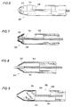
- Fig. 6 is a partial side view of an alternate embodiment of the cutting head of the invention;
- Fig. 7 is a partial side view of another alternate embodiment of the cutting head of the invention;
- Fig. 8 is a partial side view of yet another alternate embodiment of the cutting head of the invention; and
- Fig. 9 is a partial side view of another embodiment of the cutting head of the invention.
- Referring first to Fig. 1, the distal atherectomy catheter of the invention is generally identified by the
reference numeral 10. Thecatheter 10 of the invention comprises a flexibleouter catheter 12 which may be several feet in length. Acutter element housing 14 is threadably mounted or otherwise secured to the distal or forward end of thecatheter tube 12. The proximal end of thecatheter tube 12 is connected to a hand-held drive motor assembly generally identified by thereference numeral 20. - The
motor assembly 20 includes amotor 22, battery orstorage cell 24 and a chargingcoil 26 housed within a substantiallycylindrical housing 28. Themotor 22,battery 24 and chargingcoil 26 are securely retained within thehousing 28 and are electrically connected to provide sufficient power to operate thecatheter 10. Adrive shaft 30 extends axially from themotor 22. Thedrive shaft 30 extends through and is supported by abrace 32 and abushing 34 so that thedrive shaft 30 rotates freely and shaft vibration is minimized. Acoupling 36 is supported on the end of thedrive shaft 30 for connection to adrive shaft extension 38. Thedrive shaft extension 38 is hexagonal or square in cross section and fixedly secured to thecoupling 36 byset screw 40. Thedrive shaft extension 38 extends into and is received in anaxial recess 42 of adrive wire coupling 44. Theaxial recess 42 is profiled to the shape of thedrive shaft extension 38 for establishing a rotary connection between theflexible drive wire 46 and thedrive shaft 30 connected to therotary drive motor 22. - The
drive wire coupling 44 is substantially cylindrical in shape and is centrally located within thehandle housing 28. Theaxial recess 42 is of sufficient depth to permit thedrive coupling 44 to be reciprocated along the length of thedrive shaft extension 38 for reciprocally manipulating the cutting element of theapparatus 10 while maintaining rotary engagement of thedrive wire 46 with thedrive motor 22. Thedrive wire coupling 44 is manually reciprocated by moving theslide knob 48 to and fro. Adrive fork 50 connects theslide knob 48 to thedrive wire coupling 44. Thedrive fork 50, as best shown in Fig. 2, terminates in a pair of spacedarms 52 which extend about and engage thedrive wire coupling 48 within a circumferential groove defined by a pair of spacedcircumferential flange members 54 extending about the body of thedrive wire coupling 44. Theflange members 54 are sufficiently spaced and of adequate height to loosely engage thedrive fork 50 so that rotation of thedrive wire coupling 44 is not impeded even when thedrive wire coupling 44 is manually reciprocated along the drive shaft extension - The open end of the
handle housing 28 is closed by acap 56 which is threaded onto the exteriorly threadedend 58 of thehousing 28. The point of connection is sealed by agasket 60 which is slightly compressed when thecap 56 is fully threaded on theend 58 of thehousing 28. - The
cap 56 includes anaxial passage 62 extending therethrough, a portion of which is interiorly threaded for connection with a Y fitting 64 threaded thereon. Anaxial passage 66 of reduced diameter but in alignment with theaxial passage 62 extends through the Y fitting 64. Apassage 68 angularly branching from theaxial passage 66 provides an outlet connection for acannula 70 providing access to theaxial passage 36. The proximal end of thecatheter tube 12 is attached to the Y fitting 64 by acatheter retainer cap 72 threadably connected to the externally threadedend 74 of the Y fitting 64. - Referring now to Fig. 2 an on/off
switch 76 insures that the cutting element of the invention does not rotate while the catheter is being inserted into a patient. In the off position thedrive motor 22 is opened so that thedrive wire 46 is not rotated. Alocater slide 78, to be described in greater detail hereinafter is located on thehousing 28 opposite theslide knob 48. - Referring now to Fig. 3, the cutter head assembly of the invention is shown in greater detail. The cutter head assembly includes an outer
tubular housing 14 threadably secured to the distal end of thecatheter tube 12 at 80. A slot orport 82 is formed in thecutter housing 14 by removing a portion of the sidewall of thehousing 14 providing access to the interior of thehousing 14. Theslot 82 defines a "duck bill" profile terminating at apoint 84. The "duck bill" profile aides in grabbing the obstructive material to be excised. As the tissue or obstructive material enters theslot 82, it is pushed against thepoint 84 and speared and held stationary for removal by thecutter 86. - The
cutter 86 is connected to the distal end of theflexible drive wire 46. Thecutter 46 is substantially cylindrical in shape and partially hollow. A raisedportion 88 interiorly located within thecutter 86 provides a connection point for thedrive wire 46. The raisedportion 88 does not totally obstruct the interior of thecutter 86 so that a passage is defined which permits a guide wire to be passed through thecatheter 12, thecutter 86 and out aguide wire port 90 formed in the forward tip of thecutter housing 14. The sloped portion or ramp 92 of the raisedportion 88 enables the guide wire (not shown in the drawings) to conveniently pass through thecutter 86. Likewise, the slopeinner walls 94 of the forward tip of thehousing 14 direct the guide wire so that it may be conveniently threaded through theport 90. The guide wire typically extends a short distance in advance of thehousing 14 to aid in guiding the catheter of the invention in traversing the tortuous paths encountered in blood vessels, particularly the smaller blood vessels. The proximal end of thecutter 86 forms aserrated cutting edge 96 for removing occlusive material, such as plaque which coats the arterial wall. To aid the efficiency of thecutter 86, bowedwires 98 are provided to force the cutter head against the interior arterial wall of an artery orblood vessel 100 as best shown in Fig. 1. The bowedwires 98 are connected to the forward tip of thecutter housing 14 at 102 and extend exterior of thecutter housing 14 through anopening 104. Thewires 98 are welded or braised to alocater shaft 106 which extends the full length of thecatheter 12 and is connected to thelocator slide 78 which is manipulated back and forth to actuate thewires 98. Referring briefly to Fig. 5, it will be noted that thewires 98 are bent at 108 and crossed over each other. This permits the cutter head assembly to be correctly positioned against the wall of theartery 100. In operation, as thelocater slide 78 is moved forward, thewires 98 extend into theartery 100 and spread outwardly slightly so that the cutter head assembly is centrally located between thespread wires 98 substantially as shown in Fig. 4. Rotation of theslide knob 78 in the clockwise direction will lock thelocater wires 98 in the expanded position. If the catheter is to be rotated for further positioning, thewires 98 must be completely retracted flush with thecutter housing 14 so as to avoid any damage on contact of thewires 98 and the vessel wall. Thewires 98 decentralize the structure of Fig. 3 in the vessel. - Referring again to Fig. 1, the operation of the
catheter 10 will be described . Thecatheter 10 is typically inserted through the femoral artery of the patient and is directed by the physician to the site of the obstruction. If a guide wire is required, the guide wire is inserted through thecannula 70, through thecatheter 12 and out theport 90 of the forward tip of thecutter housing 14. Once the cutter head assembly is properly positioned, the guide wire is removed and vacuum pump is connected to thecannula 70 for creating a vacuum within thecatheter 12 for removal of severed or excised plaque or the like as it is severed by thecutter 86. Aseal 110 in thepassage 66 of the Y fitting 64 seals off the return passage so that plaque and the like is directed to a collection vessel connected to thecannula 70. - To operate the
catheter 10 theswitch 76 is positioned in the on position. However, when thecutter 86 is in the innermost position as shown in Fig. 3, it does not rotate because the electrical connection for providing power to themotor 28 is not yet complete. Referring to Fig. 1, theswitch 48 is provided with abrass conductor strip 112 which must engage thebrass conductor 114 to complete the circuit and provide electrical power to thedrive shaft 30. As theslide 48 is slid backward toward the base of thehandle 20, the contact between theconductor strip 112 and thebrass conductor 114 is completed and thedrive motor 22 is engaged resulting in rotation or oscillation of thedrive wire 46 which is connected to thedrive wire coupling 44 by aset screw 116. In this manner, thecutter 86 is rotated or oscillated in the range of 2,000 to 10,000 rpm while it is pulled toward the rear end of thecutter housing 14. As material is severed by thecutter 86, it is removed by the vacuum suction so that the severed material does not interfere with the cutting action of thecutter 86. - Fig. 6 is an
embodiment 120 of the cutter head which includes aforward portion 122 which can extend out of, or in advance of, thecutter housing 124 and the cutter itself is hollow having a more or less conical forward portion which is slotted so that it can cut into any obstruction that is directly in advance. It can more or less bore through a total obstruction. Thebackside 126 of the blade still has the serrated cutting edge and it can operate in the same fashion as previously described regarding thefirst embodiment 10. - Fig. 7 is a
similar structure 130 except that the conical cutter head is not exposed but it is enclosed within the forward conical portion of the cutter housing. Thecutter housing 132 is slotted and thecutter head 134 is also slotted and is hollow and may also be provided with some cutting burrs to basically cut or scrape the material as it extends through theslots 136 in the outer conical surface. Again, it also has the serrated at the back edge blade so that it will continue to perform a cutting function as it is reciprocated backwardly and the drive shaft is optionally hollow to provide the return passage for any severed material captured within the hollow cutter head. Abaffle 138 closes the cone portion of the cutter from the serrated end of the cutter. Hence, cuttings are entrapped in the cone and may be suctioned through the hollow drive wire if desired. - Fig. 8 is a
similar embodiment 140 except that thehousing 142 andcutter head 144 are generally hollow and it may have a passage for a guide wire. The surface of the conical cutter element may be provided with diamond or tungsten carbide burrs or may be a V-shaped knife having two cuttingedges 146 located diametrically opposite one another for cutting any material entering through the conic screen. The screen defines openings of specified size to enable material entry and subsequent cutting. This furnishes holes of the appropriate size to enable occlusive material cutting. As before, cuttings are flushed to the rear of the tool and vacuum removed. - Fig. 9 is another variation on essentially the same theme, except in this
embodiment 150, the substantially cylindrical shape of thecutter element 152 is constructed with either diagonal orhorizontal cutting members 154 about the body of the cutting element. The diagonal orhorizontal cutters 154 may be sharply honed to allow the cutter to be rotated or oscillated against a particularly hard material such as calcific or boney material while in contact. In this version a grinding, grating or sanding action is achieved instead of cutting. Cutter reciprocation to and fro will cut or abrade the occlusive material. Theback edge 156 is again serrated to cut material extending through thewindow 158 of thehousing 160. - While the foregoing is directed to the preferred and illustrated embodiments, the scope is determined by the claims which follow.
Claims (16)
- An atherectomy catheter for removal of occlusive material in a blood vessel, tract, or cavity, comprising:(a) a catheter tube (12);(b) a cutter head assembly mounted on the distal end of said catheter tube (12) for excising occlusive material blocking the blood vessel, tract or cavity (100);(c) flexible drive means (46) extending through said catheter tube (12);(d) a rotary cutter (86) housed within said cutter head assembly and connected to said flexible drive means (46);(e) power means (20) connected to the proximal end of said catheter tube (12) for rotating said rotary cutter (86);(f) means for urging said cutter head assembly laterally against the occlusive material; and(g) means connected to said catheter tube (12) for evacuating the excised occlusive material from the blood vessel, tract or cavity (100);characterised in that said means for urging comprises a pair of bendable wires (98) extending externally along said cutter head assembly, wherein upon actuation said wires (98) bow outwardly against the interior wall of the blood vessel, tract or cavity (100).
- A catheter according to claim 1 wherein said rotary cutter (86) includes a forwardly located cutting edge.
- A catheter according to claim 1 or claim 2 wherein said cutter head assembly (132) has a selected set of openings (136) formed in the outer surface thereof to enable occlusive material to extend thereinto for subsequent removal by said forwardly located cutting edge.
- A catheter according to any preceding claim wherein said cutter head assembly comprises an elongate, generally cylindrical housing (14).
- A catheter according to claim 4 wherein said housing has an opening (82) extending longitudinally along one side of said housing (14) for admitting occlusive material to the interior of said housing (14).
- A catheter according to claim 5 wherein said cylindrical housing (14) defines an elongate cylindrical hollow body, and said opening (82) encircles approximately one half the circumference thereof, and wherein said housing (14) includes a forwardly located full circle portion and said opening (82) is to the rear thereof.
- A catheter according to claim 5 or claim 6 wherein said pair of wires (98) extend on one side of said housing (14) diametrically opposite said opening (82).
- A catheter according to any one of claims 5 to 7 wherein said rotary cutter (86) has a rearwardly facing cutting means (96) for cutting material protruding through said opening (82) into the interior of said housing (14).
- A catheter according to claim 8 wherein said rotary cutter is retractable relative to said housing whereby said rearwardly located cutting means (96) engages the occlusive material on retraction.
- A catheter according to any preceding claim wherein the coupling between said power means and said flexible drive means permits reciprocating movement of said rotary cutter relative to said cutter head assembly.
- A catheter according to claim 10 and including means for manually imparting said reciprocating movement.
- A catheter according to claim 10 or claim 11 wherein said cutter head assembly is generally cylindrical in shape centred along and around an axis of rotation therethrough, and said cutter head assembly includes a surrounding alignment surface for guiding said rotating cutter (86) in said reciprocating movement.
- A catheter according to claim 3, or claim 4 as dependent on claim 3, wherein the outer surface is otherwise a solid member.
- A catheter according to any preceding claim wherein said rotary cutter (86, 144) connects with and is rotated by said flexible drive means (46).
- A catheter according to any preceding claim including a motorized means (20) for forming rotary motion imparted to a coupling means (36) wherein said coupling means (36) connects with said flexible drive means (46) and said drive means (46) extends along and within said catheter tube (12) to thereby impart rotative cutting action to said rotary cutter (86), and said cutter head assembly (14) is affixed to the end of said outer catheter tube (12) with said flexible drive means (46) extending therealong for rotative motion therein.
- A catheter according to any preceding claim including a control line (106) extending along said catheter tube (12) to control extension of said pair of wires (98).
Applications Claiming Priority (3)
| Application Number | Priority Date | Filing Date | Title |
|---|---|---|---|
| US07/383,606 US5087265A (en) | 1989-02-17 | 1989-07-24 | Distal atherectomy catheter |
| US383606 | 1989-07-24 | ||
| PCT/US1990/004214 WO1991001114A1 (en) | 1989-07-24 | 1990-07-23 | Improved distal atherectomy catheter |
Publications (3)
| Publication Number | Publication Date |
|---|---|
| EP0484424A1 EP0484424A1 (en) | 1992-05-13 |
| EP0484424A4 EP0484424A4 (en) | 1992-11-19 |
| EP0484424B1 true EP0484424B1 (en) | 1996-07-03 |
Family
ID=23513894
Family Applications (1)
| Application Number | Title | Priority Date | Filing Date |
|---|---|---|---|
| EP90911965A Expired - Lifetime EP0484424B1 (en) | 1989-07-24 | 1990-07-23 | Improved distal atherectomy catheter |
Country Status (11)
| Country | Link |
|---|---|
| US (2) | US5087265A (en) |
| EP (1) | EP0484424B1 (en) |
| JP (1) | JPH05501074A (en) |
| AT (1) | ATE139895T1 (en) |
| AU (1) | AU651950B2 (en) |
| CA (1) | CA2063741A1 (en) |
| DE (1) | DE69027681T2 (en) |
| ES (1) | ES2089023T3 (en) |
| FI (1) | FI920301A0 (en) |
| RU (1) | RU2068239C1 (en) |
| WO (1) | WO1991001114A1 (en) |
Families Citing this family (245)
| Publication number | Priority date | Publication date | Assignee | Title |
|---|---|---|---|---|
| GB8829182D0 (en) | 1988-12-14 | 1989-01-25 | Univ Birmingham | Surgical instrument |
| US5087265A (en) * | 1989-02-17 | 1992-02-11 | American Biomed, Inc. | Distal atherectomy catheter |
| US5728129A (en) * | 1989-02-17 | 1998-03-17 | American Biomed, Inc. | Distal atherectomy catheter |
| WO1992014413A1 (en) * | 1991-02-19 | 1992-09-03 | Fischell Robert | Improved apparatus and method for atherectomy |
| US5275607A (en) * | 1991-09-23 | 1994-01-04 | Visionary Medical, Inc. | Intraocular surgical scissors |
| US5197485A (en) * | 1991-10-15 | 1993-03-30 | Pilling Co. | Method and apparatus for sampling aortic plaque |
| US6936025B1 (en) * | 1992-05-19 | 2005-08-30 | Bacchus Vascular, Inc. | Thrombolysis device |
| US5643297A (en) | 1992-11-09 | 1997-07-01 | Endovascular Instruments, Inc. | Intra-artery obstruction clearing apparatus and methods |
| US5571122A (en) | 1992-11-09 | 1996-11-05 | Endovascular Instruments, Inc. | Unitary removal of plaque |
| CA2118886C (en) * | 1993-05-07 | 1998-12-08 | Dennis Vigil | Method and apparatus for dilatation of a stenotic vessel |
| US5417703A (en) * | 1993-07-13 | 1995-05-23 | Scimed Life Systems, Inc. | Thrombectomy devices and methods of using same |
| US5419774A (en) * | 1993-07-13 | 1995-05-30 | Scimed Life Systems, Inc. | Thrombus extraction device |
| US5441510A (en) * | 1993-09-01 | 1995-08-15 | Technology Development Center | Bi-axial cutter apparatus for catheter |
| US5462529A (en) * | 1993-09-29 | 1995-10-31 | Technology Development Center | Adjustable treatment chamber catheter |
| WO1995016141A1 (en) * | 1993-12-09 | 1995-06-15 | Devices For Vascular Intervention, Inc. | Composite drive shaft |
| US5522824A (en) * | 1994-01-24 | 1996-06-04 | Applied Medical Resources Corporation | Valvulotome and method for making and using same |
| US5499632A (en) * | 1994-05-04 | 1996-03-19 | Devices For Vascular Intervention | Guide wire migration controller |
| US5919161A (en) * | 1994-05-04 | 1999-07-06 | Devices For Vascular Intervention | Guidewire migration controller |
| US5547469A (en) * | 1994-05-13 | 1996-08-20 | Boston Scientific Corporation | Apparatus for performing diagnostic and therapeutic modalities in the biliary tree |
| US6743217B2 (en) | 1994-05-13 | 2004-06-01 | Scimed Life Systems, Inc. | Apparatus for performing diagnostic and therapeutic modalities in the biliary tree |
| CA2202613C (en) * | 1994-10-31 | 2006-06-06 | Michael S. H. Chu | Biopsy needle |
| US5665062A (en) * | 1995-01-23 | 1997-09-09 | Houser; Russell A. | Atherectomy catheter and RF cutting method |
| ES2174056T3 (en) * | 1995-03-28 | 2002-11-01 | Straub Medical Ag | CATHETER TO UNLOCK ABNORMAL INCRUSTATIONS IN HUMAN BLOOD VESSELS. |
| US5728123A (en) * | 1995-04-26 | 1998-03-17 | Lemelson; Jerome H. | Balloon actuated catheter |
| US5658302A (en) * | 1995-06-07 | 1997-08-19 | Baxter International Inc. | Method and device for endoluminal disruption of venous valves |
| US5782795A (en) * | 1995-06-30 | 1998-07-21 | Xomed Surgical Products, Inc. | Surgical suction cutting instrument with internal irrigation |
| US5733296A (en) * | 1996-02-06 | 1998-03-31 | Devices For Vascular Intervention | Composite atherectomy cutter |
| US6152909A (en) * | 1996-05-20 | 2000-11-28 | Percusurge, Inc. | Aspiration system and method |
| US6270477B1 (en) * | 1996-05-20 | 2001-08-07 | Percusurge, Inc. | Catheter for emboli containment |
| US5662671A (en) * | 1996-07-17 | 1997-09-02 | Embol-X, Inc. | Atherectomy device having trapping and excising means for removal of plaque from the aorta and other arteries |
| US6569147B1 (en) | 1996-07-26 | 2003-05-27 | Kensey Nash Corporation | Systems and methods of use for delivering beneficial agents for revascularizing stenotic bypass grafts and other occluded blood vessels and for other purposes |
| US6652546B1 (en) * | 1996-07-26 | 2003-11-25 | Kensey Nash Corporation | System and method of use for revascularizing stenotic bypass grafts and other occluded blood vessels |
| US6905505B2 (en) * | 1996-07-26 | 2005-06-14 | Kensey Nash Corporation | System and method of use for agent delivery and revascularizing of grafts and vessels |
| US6830577B2 (en) * | 1996-07-26 | 2004-12-14 | Kensey Nash Corporation | System and method of use for treating occluded vessels and diseased tissue |
| US5779721A (en) * | 1996-07-26 | 1998-07-14 | Kensey Nash Corporation | System and method of use for revascularizing stenotic bypass grafts and other blood vessels |
| US6080170A (en) * | 1996-07-26 | 2000-06-27 | Kensey Nash Corporation | System and method of use for revascularizing stenotic bypass grafts and other occluded blood vessels |
| US6120520A (en) | 1997-05-27 | 2000-09-19 | Angiotrax, Inc. | Apparatus and methods for stimulating revascularization and/or tissue growth |
| US6102926A (en) * | 1996-12-02 | 2000-08-15 | Angiotrax, Inc. | Apparatus for percutaneously performing myocardial revascularization having means for sensing tissue parameters and methods of use |
| US6051008A (en) * | 1996-12-02 | 2000-04-18 | Angiotrax, Inc. | Apparatus having stabilization members for percutaneously performing surgery and methods of use |
| US5882329A (en) * | 1997-02-12 | 1999-03-16 | Prolifix Medical, Inc. | Apparatus and method for removing stenotic material from stents |
| JP2001512334A (en) | 1997-02-12 | 2001-08-21 | プロリフィックス メディカル,インコーポレイテッド | Equipment for removing material from stents |
| US7094249B1 (en) | 1997-03-06 | 2006-08-22 | Boston Scientific Scimed, Inc. | Distal protection device and method |
| US6849068B1 (en) | 1997-03-06 | 2005-02-01 | Medtronic Ave, Inc. | Aspiration catheter |
| US5814064A (en) * | 1997-03-06 | 1998-09-29 | Scimed Life Systems, Inc. | Distal protection device |
| US6024751A (en) * | 1997-04-11 | 2000-02-15 | Coherent Inc. | Method and apparatus for transurethral resection of the prostate |
| US6156049A (en) * | 1997-04-11 | 2000-12-05 | Coherent Inc. | Method and apparatus for transurethral resection of the prostate |
| US5911734A (en) | 1997-05-08 | 1999-06-15 | Embol-X, Inc. | Percutaneous catheter and guidewire having filter and medical device deployment capabilities |
| US6676682B1 (en) | 1997-05-08 | 2004-01-13 | Scimed Life Systems, Inc. | Percutaneous catheter and guidewire having filter and medical device deployment capabilities |
| US6090118A (en) | 1998-07-23 | 2000-07-18 | Mcguckin, Jr.; James F. | Rotational thrombectomy apparatus and method with standing wave |
| US7037316B2 (en) * | 1997-07-24 | 2006-05-02 | Mcguckin Jr James F | Rotational thrombectomy device |
| US6051011A (en) * | 1997-08-28 | 2000-04-18 | Bausch & Lomb Surgical, Inc. | Surgical handpiece |
| US6142955A (en) | 1997-09-19 | 2000-11-07 | United States Surgical Corporation | Biopsy apparatus and method |
| US6066149A (en) * | 1997-09-30 | 2000-05-23 | Target Therapeutics, Inc. | Mechanical clot treatment device with distal filter |
| US6027514A (en) * | 1997-12-17 | 2000-02-22 | Fox Hollow Technologies, Inc. | Apparatus and method for removing occluding material from body lumens |
| US6267679B1 (en) | 1997-12-31 | 2001-07-31 | Jack W. Romano | Method and apparatus for transferring drilling energy to a cutting member |
| US5931845A (en) * | 1998-02-20 | 1999-08-03 | Amyette; Carol R. | Pierced body part cleaning device |
| US6146395A (en) | 1998-03-05 | 2000-11-14 | Scimed Life Systems, Inc. | Ablation burr |
| US6001112A (en) | 1998-04-10 | 1999-12-14 | Endicor Medical, Inc. | Rotational atherectomy device |
| US6666874B2 (en) * | 1998-04-10 | 2003-12-23 | Endicor Medical, Inc. | Rotational atherectomy system with serrated cutting tip |
| US6482217B1 (en) | 1998-04-10 | 2002-11-19 | Endicor Medical, Inc. | Neuro thrombectomy catheter |
| US6080176A (en) * | 1998-10-30 | 2000-06-27 | Atrion Medical Products, Inc. | Medical punch with high shear angle cutting edges |
| US6758851B2 (en) | 1999-02-02 | 2004-07-06 | Samuel Shiber | Vessel cleaner |
| US7316697B2 (en) * | 1999-02-02 | 2008-01-08 | Samuel Shiber | Vessel cleaning system with asymmetrical auto retracting agitator |
| US6818002B2 (en) * | 1999-02-02 | 2004-11-16 | Samuel Shiber | Vessel cleaner and barrier |
| US6113615A (en) * | 1999-02-03 | 2000-09-05 | Scimed Life Systems, Inc. | Atherectomy burr including a bias wire |
| US6171327B1 (en) * | 1999-02-24 | 2001-01-09 | Scimed Life Systems, Inc. | Intravascular filter and method |
| US6645217B1 (en) | 1999-05-15 | 2003-11-11 | Advanced Cardiovascular Systems, Inc. | Over-the-wire atherectomy catheter |
| US20030150821A1 (en) * | 1999-07-16 | 2003-08-14 | Bates Mark C. | Emboli filtration system and methods of use |
| US6371970B1 (en) | 1999-07-30 | 2002-04-16 | Incept Llc | Vascular filter having articulation region and methods of use in the ascending aorta |
| US6616679B1 (en) | 1999-07-30 | 2003-09-09 | Incept, Llc | Rapid exchange vascular device for emboli and thrombus removal and methods of use |
| US7320697B2 (en) * | 1999-07-30 | 2008-01-22 | Boston Scientific Scimed, Inc. | One piece loop and coil |
| US6530939B1 (en) | 1999-07-30 | 2003-03-11 | Incept, Llc | Vascular device having articulation region and methods of use |
| US20020022858A1 (en) * | 1999-07-30 | 2002-02-21 | Demond Jackson F. | Vascular device for emboli removal having suspension strut and methods of use |
| US6620182B1 (en) | 1999-07-30 | 2003-09-16 | Incept Llc | Vascular filter having articulation region and methods of use in the ascending aorta |
| US6544279B1 (en) | 2000-08-09 | 2003-04-08 | Incept, Llc | Vascular device for emboli, thrombus and foreign body removal and methods of use |
| US6589263B1 (en) | 1999-07-30 | 2003-07-08 | Incept Llc | Vascular device having one or more articulation regions and methods of use |
| US6142987A (en) | 1999-08-03 | 2000-11-07 | Scimed Life Systems, Inc. | Guided filter with support wire and methods of use |
| US6235044B1 (en) * | 1999-08-04 | 2001-05-22 | Scimed Life Systems, Inc. | Percutaneous catheter and guidewire for filtering during ablation of mycardial or vascular tissue |
| US6168579B1 (en) * | 1999-08-04 | 2001-01-02 | Scimed Life Systems, Inc. | Filter flush system and methods of use |
| US6299622B1 (en) | 1999-08-19 | 2001-10-09 | Fox Hollow Technologies, Inc. | Atherectomy catheter with aligned imager |
| US7708749B2 (en) | 2000-12-20 | 2010-05-04 | Fox Hollow Technologies, Inc. | Debulking catheters and methods |
| US20030125757A1 (en) * | 2000-12-20 | 2003-07-03 | Fox Hollow Technologies, Inc. | Debulking catheters and methods |
| US7713279B2 (en) | 2000-12-20 | 2010-05-11 | Fox Hollow Technologies, Inc. | Method and devices for cutting tissue |
| US20030120295A1 (en) * | 2000-12-20 | 2003-06-26 | Fox Hollow Technologies, Inc. | Debulking catheters and methods |
| US8328829B2 (en) | 1999-08-19 | 2012-12-11 | Covidien Lp | High capacity debulking catheter with razor edge cutting window |
| US6447525B2 (en) | 1999-08-19 | 2002-09-10 | Fox Hollow Technologies, Inc. | Apparatus and methods for removing material from a body lumen |
| US6638233B2 (en) * | 1999-08-19 | 2003-10-28 | Fox Hollow Technologies, Inc. | Apparatus and methods for material capture and removal |
| US7887556B2 (en) | 2000-12-20 | 2011-02-15 | Fox Hollow Technologies, Inc. | Debulking catheters and methods |
| AU2614901A (en) | 1999-10-22 | 2001-04-30 | Boston Scientific Corporation | Double balloon thrombectomy catheter |
| US8414543B2 (en) | 1999-10-22 | 2013-04-09 | Rex Medical, L.P. | Rotational thrombectomy wire with blocking device |
| US6371971B1 (en) | 1999-11-15 | 2002-04-16 | Scimed Life Systems, Inc. | Guidewire filter and methods of use |
| US6352544B1 (en) | 2000-02-22 | 2002-03-05 | Gregory A. Spitz | Apparatus and methods for removing veins |
| US6408649B1 (en) * | 2000-04-28 | 2002-06-25 | Gyrotron Technology, Inc. | Method for the rapid thermal treatment of glass and glass-like materials using microwave radiation |
| US6712773B1 (en) * | 2000-09-11 | 2004-03-30 | Tyco Healthcare Group Lp | Biopsy system |
| US6616681B2 (en) | 2000-10-05 | 2003-09-09 | Scimed Life Systems, Inc. | Filter delivery and retrieval device |
| JP3996057B2 (en) * | 2000-11-27 | 2007-10-24 | タイコ ヘルスケア グループ リミテッド パートナーシップ | Tissue extractor |
| US6419641B1 (en) | 2000-11-28 | 2002-07-16 | Promex, Llc | Flexible tip medical instrument |
| WO2002049690A2 (en) | 2000-12-20 | 2002-06-27 | Fox Hollow Technologies, Inc. | Debulking catheter |
| US20040167554A1 (en) * | 2000-12-20 | 2004-08-26 | Fox Hollow Technologies, Inc. | Methods and devices for reentering a true lumen from a subintimal space |
| US7699790B2 (en) * | 2000-12-20 | 2010-04-20 | Ev3, Inc. | Debulking catheters and methods |
| US7927784B2 (en) * | 2000-12-20 | 2011-04-19 | Ev3 | Vascular lumen debulking catheters and methods |
| US20050154407A1 (en) * | 2000-12-20 | 2005-07-14 | Fox Hollow Technologies, Inc. | Method of evaluating drug efficacy for treating atherosclerosis |
| US20100121360A9 (en) * | 2000-12-20 | 2010-05-13 | Fox Hollow Technologies, Inc | Testing a patient population having a cardiovascular condition for drug efficacy |
| US20060235366A1 (en) * | 2000-12-20 | 2006-10-19 | Fox Hollow Technologies, Inc. | Method of evaluating a treatment for vascular disease |
| US6663651B2 (en) | 2001-01-16 | 2003-12-16 | Incept Llc | Systems and methods for vascular filter retrieval |
| US6579300B2 (en) | 2001-01-18 | 2003-06-17 | Scimed Life Systems, Inc. | Steerable sphincterotome and methods for cannulation, papillotomy and sphincterotomy |
| US6689151B2 (en) | 2001-01-25 | 2004-02-10 | Scimed Life Systems, Inc. | Variable wall thickness for delivery sheath housing |
| US6840950B2 (en) * | 2001-02-20 | 2005-01-11 | Scimed Life Systems, Inc. | Low profile emboli capture device |
| US6537295B2 (en) | 2001-03-06 | 2003-03-25 | Scimed Life Systems, Inc. | Wire and lock mechanism |
| WO2002089246A2 (en) * | 2001-04-27 | 2002-11-07 | Tyco Electronics Logistics Ag | Diversity slot antenna |
| US7105012B2 (en) * | 2001-06-19 | 2006-09-12 | Eva Corporation | Positioning assembly and method of use |
| US6951570B2 (en) * | 2001-07-02 | 2005-10-04 | Rubicon Medical, Inc. | Methods, systems, and devices for deploying a filter from a filter device |
| US6997939B2 (en) * | 2001-07-02 | 2006-02-14 | Rubicon Medical, Inc. | Methods, systems, and devices for deploying an embolic protection filter |
| US6962598B2 (en) * | 2001-07-02 | 2005-11-08 | Rubicon Medical, Inc. | Methods, systems, and devices for providing embolic protection |
| US20030023263A1 (en) * | 2001-07-24 | 2003-01-30 | Incept Llc | Apparatus and methods for aspirating emboli |
| US20030023261A1 (en) * | 2001-07-30 | 2003-01-30 | Scimed Life Systems Inc. | Chronic total occlusion device with variable stiffness shaft |
| US6878151B2 (en) * | 2001-09-27 | 2005-04-12 | Scimed Life Systems, Inc. | Medical retrieval device |
| US6755847B2 (en) * | 2001-10-05 | 2004-06-29 | Scimed Life Systems, Inc. | Emboli capturing device and method of manufacture therefor |
| US20030069597A1 (en) * | 2001-10-10 | 2003-04-10 | Scimed Life Systems, Inc. | Loading tool |
| US20030078614A1 (en) * | 2001-10-18 | 2003-04-24 | Amr Salahieh | Vascular embolic filter devices and methods of use therefor |
| US7749243B2 (en) * | 2001-10-19 | 2010-07-06 | Boston Scientific Scimed, Inc. | Embolus extractor |
| US7052500B2 (en) | 2001-10-19 | 2006-05-30 | Scimed Life Systems, Inc. | Embolus extractor |
| US20030083692A1 (en) * | 2001-10-29 | 2003-05-01 | Scimed Life Systems, Inc. | Distal protection device and method of use thereof |
| US7594926B2 (en) * | 2001-11-09 | 2009-09-29 | Boston Scientific Scimed, Inc. | Methods, systems and devices for delivering stents |
| CA2466037C (en) * | 2001-11-09 | 2010-12-21 | Rubicon Medical, Inc. | Stent delivery device with embolic protection |
| US8468678B2 (en) | 2002-10-02 | 2013-06-25 | Boston Scientific Scimed, Inc. | Expandable retrieval device |
| US7998163B2 (en) * | 2002-10-03 | 2011-08-16 | Boston Scientific Scimed, Inc. | Expandable retrieval device |
| US6904663B2 (en) * | 2002-11-04 | 2005-06-14 | Taylor Made Golf Company, Inc. | Method for manufacturing a golf club face |
| US8627992B2 (en) * | 2002-12-16 | 2014-01-14 | Edrich Health Technologies, Inc. | Endovascular stapler |
| US7399310B2 (en) * | 2002-12-16 | 2008-07-15 | Edrich Vascular Devices, Inc. | Endovascular stapler |
| US20040138694A1 (en) * | 2003-01-15 | 2004-07-15 | Scimed Life Systems, Inc. | Intravascular filtering membrane and method of making an embolic protection filter device |
| US8142457B2 (en) * | 2003-03-26 | 2012-03-27 | Boston Scientific Scimed, Inc. | Percutaneous transluminal endarterectomy |
| US20040199201A1 (en) * | 2003-04-02 | 2004-10-07 | Scimed Life Systems, Inc. | Embolectomy devices |
| US8246640B2 (en) | 2003-04-22 | 2012-08-21 | Tyco Healthcare Group Lp | Methods and devices for cutting tissue at a vascular location |
| US20040215222A1 (en) * | 2003-04-25 | 2004-10-28 | Michael Krivoruchko | Intravascular material removal device |
| US20040220612A1 (en) * | 2003-04-30 | 2004-11-04 | Swainston Kyle W | Slidable capture catheter |
| US7780611B2 (en) * | 2003-05-01 | 2010-08-24 | Boston Scientific Scimed, Inc. | Medical instrument with controlled torque transmission |
| US7632288B2 (en) | 2003-05-12 | 2009-12-15 | Boston Scientific Scimed, Inc. | Cutting balloon catheter with improved pushability |
| US7758604B2 (en) | 2003-05-29 | 2010-07-20 | Boston Scientific Scimed, Inc. | Cutting balloon catheter with improved balloon configuration |
| US20050004594A1 (en) * | 2003-07-02 | 2005-01-06 | Jeffrey Nool | Devices and methods for aspirating from filters |
| US7780626B2 (en) * | 2003-08-08 | 2010-08-24 | Boston Scientific Scimed, Inc. | Catheter shaft for regulation of inflation and deflation |
| US7887557B2 (en) * | 2003-08-14 | 2011-02-15 | Boston Scientific Scimed, Inc. | Catheter having a cutting balloon including multiple cavities or multiple channels |
| US8535344B2 (en) * | 2003-09-12 | 2013-09-17 | Rubicon Medical, Inc. | Methods, systems, and devices for providing embolic protection and removing embolic material |
| US7651514B2 (en) * | 2003-12-11 | 2010-01-26 | Boston Scientific Scimed, Inc. | Nose rider improvement for filter exchange and methods of use |
| US20050159772A1 (en) * | 2004-01-20 | 2005-07-21 | Scimed Life Systems, Inc. | Sheath for use with an embolic protection filtering device |
| US20050159773A1 (en) * | 2004-01-20 | 2005-07-21 | Scimed Life Systems, Inc. | Expandable retrieval device with dilator tip |
| EP2014244B1 (en) | 2004-03-04 | 2011-10-26 | Straub Medical AG | Working head on a catheter for suction, fragmenting and removing material extractable from blood vessels. |
| US7473265B2 (en) | 2004-03-15 | 2009-01-06 | Boston Scientific Scimed, Inc. | Filter media and methods of manufacture |
| US8100822B2 (en) | 2004-03-16 | 2012-01-24 | Macroplata Systems, Llc | Anoscope for treating hemorrhoids without the trauma of cutting or the use of an endoscope |
| US7754047B2 (en) * | 2004-04-08 | 2010-07-13 | Boston Scientific Scimed, Inc. | Cutting balloon catheter and method for blade mounting |
| US7566319B2 (en) | 2004-04-21 | 2009-07-28 | Boston Scientific Scimed, Inc. | Traction balloon |
| US20050240215A1 (en) * | 2004-04-21 | 2005-10-27 | Scimed Life Systems, Inc. | Magnetic embolic protection device and method |
| US8920402B2 (en) | 2004-04-27 | 2014-12-30 | The Spectranetics Corporation | Thrombectomy and soft debris removal device |
| US7959608B2 (en) * | 2004-04-27 | 2011-06-14 | The Spectranetics Corporation | Thrombectomy and soft debris removal device |
| US7585307B2 (en) * | 2004-05-17 | 2009-09-08 | Edrich Health Technologies, Inc. | Surgical stapling system |
| US20060293612A1 (en) * | 2004-06-24 | 2006-12-28 | Boston Scientific Scimed, Inc. | Apparatus and method for treating occluded vasculature |
| US8241315B2 (en) * | 2004-06-24 | 2012-08-14 | Boston Scientific Scimed, Inc. | Apparatus and method for treating occluded vasculature |
| US7794472B2 (en) * | 2004-08-11 | 2010-09-14 | Boston Scientific Scimed, Inc. | Single wire intravascular filter |
| US7621904B2 (en) | 2004-10-21 | 2009-11-24 | Boston Scientific Scimed, Inc. | Catheter with a pre-shaped distal tip |
| US20060095067A1 (en) * | 2004-11-01 | 2006-05-04 | Horng-Ban Lin | Lubricious filter |
| US8038691B2 (en) | 2004-11-12 | 2011-10-18 | Boston Scientific Scimed, Inc. | Cutting balloon catheter having flexible atherotomes |
| US7291158B2 (en) * | 2004-11-12 | 2007-11-06 | Boston Scientific Scimed, Inc. | Cutting balloon catheter having a segmented blade |
| US8038696B2 (en) * | 2004-12-06 | 2011-10-18 | Boston Scientific Scimed, Inc. | Sheath for use with an embolic protection filter |
| US20110236902A1 (en) * | 2004-12-13 | 2011-09-29 | Tyco Healthcare Group Lp | Testing a patient population having a cardiovascular condition for drug efficacy |
| US7478465B1 (en) | 2005-01-10 | 2009-01-20 | Boston Scientific Scimed, Inc. | Method of securing a restraining member on a medical device |
| US7204464B2 (en) * | 2005-01-21 | 2007-04-17 | Boston Scientific Scimed, Inc. | Medical wire holder |
| US8480629B2 (en) * | 2005-01-28 | 2013-07-09 | Boston Scientific Scimed, Inc. | Universal utility board for use with medical devices and methods of use |
| US20060184191A1 (en) * | 2005-02-11 | 2006-08-17 | Boston Scientific Scimed, Inc. | Cutting balloon catheter having increased flexibility regions |
| US7794413B2 (en) * | 2005-04-19 | 2010-09-14 | Ev3, Inc. | Libraries and data structures of materials removed by debulking catheters |
| US20070038173A1 (en) * | 2005-07-27 | 2007-02-15 | Fox Hollow Technologies, Inc. | Methods affecting markers in patients having vascular disease |
| US7989207B2 (en) * | 2006-02-17 | 2011-08-02 | Tyco Healthcare Group Lp | Testing lumenectomy samples for markers of non-vascular diseases |
| US20070276419A1 (en) | 2006-05-26 | 2007-11-29 | Fox Hollow Technologies, Inc. | Methods and devices for rotating an active element and an energy emitter on a catheter |
| CA2921604C (en) | 2006-09-13 | 2020-02-25 | Vascular Insights Llc | Vascular treatment device |
| FR2903292A1 (en) * | 2006-11-28 | 2008-01-11 | Perouse Soc Par Actions Simpli | Surgical cutting tool for cardiac surgery field, has cutting head with blade and counter blade mobile with respect to each other for defining cutting line, and unit controlling relative displacement of blade and counter blade |
| US8784440B2 (en) | 2008-02-25 | 2014-07-22 | Covidien Lp | Methods and devices for cutting tissue |
| US20090230167A1 (en) * | 2008-03-17 | 2009-09-17 | Medtronic Vascular, Inc. | Endostapler Biasing Mechanism |
| US9101387B2 (en) * | 2008-06-05 | 2015-08-11 | Cardiovascular Systems, Inc. | Directional rotational atherectomy device with offset spinning abrasive element |
| KR101645754B1 (en) | 2008-10-13 | 2016-08-04 | 코비디엔 엘피 | Devices and methods for manipulating a catheter shaft |
| CH699981A2 (en) | 2008-11-27 | 2010-05-31 | Straub Medical Ag | Catheter for aspirating, fragmenting and out transport of removable material from blood vessels. |
| US8444669B2 (en) | 2008-12-15 | 2013-05-21 | Boston Scientific Scimed, Inc. | Embolic filter delivery system and method |
| US20100152711A1 (en) * | 2008-12-15 | 2010-06-17 | Boston Scientific Scimed, Inc. | Offset coupling region |
| US8795303B2 (en) * | 2009-02-02 | 2014-08-05 | Cardiovascular Systems, Inc. | Multi-material abrading head for atherectomy devices having laterally displaced center of mass |
| US9687266B2 (en) | 2009-04-29 | 2017-06-27 | Covidien Lp | Methods and devices for cutting and abrading tissue |
| CA2761774C (en) | 2009-05-14 | 2014-09-16 | Tyco Healthcare Group Lp | Easily cleaned atherectomy catheters and methods of use |
| CH701695A1 (en) | 2009-08-27 | 2011-02-28 | Straub Medical Ag | Catheter with protection system for aspirating, fragmenting and out pumping of removable material from hollow bodies or vessels, in particular of the human or animal body. |
| EP2913013B1 (en) | 2009-12-02 | 2016-11-09 | Covidien LP | Methods and devices for cutting tissue |
| RU2520801C2 (en) | 2009-12-11 | 2014-06-27 | ТАЙКО ХЕЛСКЕА ГРУП эЛПи | Device for material removal with improved capture efficiency and methods for using |
| US10966701B2 (en) | 2009-12-16 | 2021-04-06 | Boston Scientific Scimed, Inc. | Tissue retractor for minimally invasive surgery |
| US10595711B2 (en) | 2009-12-16 | 2020-03-24 | Boston Scientific Scimed, Inc. | System for a minimally-invasive, operative gastrointestinal treatment |
| US9565998B2 (en) | 2009-12-16 | 2017-02-14 | Boston Scientific Scimed, Inc. | Multi-lumen-catheter retractor system for a minimally-invasive, operative gastrointestinal treatment |
| US9186131B2 (en) | 2009-12-16 | 2015-11-17 | Macroplata, Inc. | Multi-lumen-catheter retractor system for a minimally-invasive, operative gastrointestinal treatment |
| US8932211B2 (en) | 2012-06-22 | 2015-01-13 | Macroplata, Inc. | Floating, multi-lumen-catheter retractor system for a minimally-invasive, operative gastrointestinal treatment |
| US10758116B2 (en) | 2009-12-16 | 2020-09-01 | Boston Scientific Scimed, Inc. | System for a minimally-invasive, operative gastrointestinal treatment |
| EP3659666A1 (en) | 2009-12-16 | 2020-06-03 | Boston Scientific Scimed Inc. | Arrangements and methods for effecting an endoluminal anatomical structure |
| US10531869B2 (en) | 2009-12-16 | 2020-01-14 | Boston Scientific Scimed, Inc. | Tissue retractor for minimally invasive surgery |
| USRE48850E1 (en) | 2009-12-16 | 2021-12-14 | Boston Scientific Scimed, Inc. | Multi-lumen-catheter retractor system for a minimally-invasive, operative gastrointestinal treatment |
| US11344285B2 (en) | 2009-12-16 | 2022-05-31 | Boston Scientific Scimed, Inc. | Multi-lumen-catheter retractor system for a minimally-invasive, operative gastrointestinal treatment |
| US9050126B2 (en) | 2010-02-26 | 2015-06-09 | Cardiovascular Systems, Inc. | Rotational atherectomy device with electric motor |
| RU2538174C2 (en) | 2010-06-14 | 2015-01-10 | Ковидиен Лп | Device for material removal |
| US11000307B2 (en) | 2010-10-19 | 2021-05-11 | Minerva Surgical Inc. | Apparatus for rotating medical devices, systems including the apparatus, and associated methods |
| KR101518147B1 (en) | 2010-10-28 | 2015-05-06 | 코비디엔 엘피 | Material removal device and method of use |
| EP2637567B1 (en) | 2010-11-11 | 2017-03-08 | Covidien LP | Flexible debulking catheters with imaging and methods of manufacture |
| US9585667B2 (en) | 2010-11-15 | 2017-03-07 | Vascular Insights Llc | Sclerotherapy catheter with lumen having wire rotated by motor and simultaneous withdrawal from vein |
| US8821478B2 (en) | 2011-03-04 | 2014-09-02 | Boston Scientific Scimed, Inc. | Catheter with variable stiffness |
| US9055951B2 (en) | 2011-05-23 | 2015-06-16 | Covidien Lp | Endovascular tissue removal device |
| JP5806407B2 (en) | 2011-09-01 | 2015-11-10 | コヴィディエン リミテッド パートナーシップ | Catheter with helical drive shaft and manufacturing method |
| US20130085514A1 (en) * | 2011-09-30 | 2013-04-04 | Tyco Healthcare Group Lp | Rotating occlusion treatment system |
| US10213533B2 (en) * | 2012-03-05 | 2019-02-26 | Keith A. Walter | Medical tools with aspiration tips suitable for cataract surgeries and related methods |
| WO2014012011A1 (en) * | 2012-07-13 | 2014-01-16 | Boston Scientific Scimed, Inc. | Wire-guided recanalization system |
| US10342699B2 (en) | 2012-08-03 | 2019-07-09 | J.D. Franco & Co., Llc | Systems and methods for treating eye diseases |
| US9579157B2 (en) | 2012-09-13 | 2017-02-28 | Covidien Lp | Cleaning device for medical instrument and method of use |
| US9943329B2 (en) | 2012-11-08 | 2018-04-17 | Covidien Lp | Tissue-removing catheter with rotatable cutter |
| KR101717387B1 (en) | 2012-11-08 | 2017-03-16 | 코비디엔 엘피 | Tissue-removing catheter including operational control mechanism |
| US9468458B2 (en) * | 2012-12-05 | 2016-10-18 | Michael B. McDonald | Aortic valve cutter |
| US9271750B2 (en) | 2013-03-13 | 2016-03-01 | Kyphon Sarl | Expandable cannula and method of use |
| US9936970B2 (en) | 2013-03-14 | 2018-04-10 | Cardiovascular Systems, Inc. | Devices, systems and methods for an oscillating crown drive for rotational atherectomy |
| US9750525B2 (en) | 2013-03-14 | 2017-09-05 | Cardiovascular Systems, Inc. | Devices, systems and methods for an oscillating crown drive for rotational atherectomy |
| US9198684B2 (en) | 2013-03-15 | 2015-12-01 | Kyphon Sarl | Surgical cutting device having a blunt tip for protecting tissue adjacent targeted tissue and method for use thereof |
| US9468457B2 (en) | 2013-09-30 | 2016-10-18 | Cardiovascular Systems, Inc. | Atherectomy device with eccentric crown |
| USD766433S1 (en) | 2013-11-04 | 2016-09-13 | Cardiovascular Systems, Inc. | Eccentric crown |
| US10052122B2 (en) | 2014-01-17 | 2018-08-21 | Cardiovascular Systems, Inc. | Spin-to-open atherectomy device with electric motor control |
| US9456843B2 (en) | 2014-02-03 | 2016-10-04 | Covidien Lp | Tissue-removing catheter including angular displacement sensor |
| US9526519B2 (en) | 2014-02-03 | 2016-12-27 | Covidien Lp | Tissue-removing catheter with improved angular tissue-removing positioning within body lumen |
| CN106456207B (en) * | 2014-04-28 | 2020-09-29 | 密涅瓦外科有限公司 | Tissue resector with cutting wire, manually operated tissue resector system, and related methods |
| US10667836B2 (en) | 2014-04-28 | 2020-06-02 | Boston Scientific Scimed, Inc. | Tissue resectors, hand operated tissue resecting systems, and associated methods |
| FR3021860A1 (en) * | 2014-06-05 | 2015-12-11 | Bernard Pain | TRANSCATHETER DEVICE FOR ABLATION OF CALCIFIED FABRICS AT THE LEVELS OF AN AORTIC VALVE |
| WO2015200702A1 (en) | 2014-06-27 | 2015-12-30 | Covidien Lp | Cleaning device for catheter and catheter including the same |
| EP3242612B1 (en) | 2015-01-08 | 2020-08-26 | Sinusafe Medical Ltd | Paranasal sinus medical device |
| JP6706611B2 (en) * | 2015-03-20 | 2020-06-10 | テルモ株式会社 | Catheter system and treatment method |
| US10314667B2 (en) | 2015-03-25 | 2019-06-11 | Covidien Lp | Cleaning device for cleaning medical instrument |
| US10292721B2 (en) | 2015-07-20 | 2019-05-21 | Covidien Lp | Tissue-removing catheter including movable distal tip |
| US10314664B2 (en) | 2015-10-07 | 2019-06-11 | Covidien Lp | Tissue-removing catheter and tissue-removing element with depth stop |
| US10869688B2 (en) * | 2015-10-30 | 2020-12-22 | Terumo Kabushiki Kaisha | Device handle for a medical device |
| CN105688292A (en) * | 2016-03-14 | 2016-06-22 | 崔建忠 | Multifunctional brain aspirator having smashing and sucking functions |
| RU178024U1 (en) * | 2016-05-05 | 2018-03-19 | государственное бюджетное образовательное учреждение высшего профессионального образования "Омский государственный медицинский университет" Министерства здравоохранения Российской Федерации (ГБОУ ВПО ОмГМУ Минздрава России) | Aterectomy catheter to remove clogging material |
| US11083484B2 (en) | 2016-07-03 | 2021-08-10 | Sinusafe Medical Ltd. | Medical device for treatment of a sinus and/or an ear and methods of use thereof |
| US11071534B2 (en) | 2016-12-30 | 2021-07-27 | Boston Scientific Scimed, Inc. | System for a minimally-invasive treatment within a body lumen |
| CA3051126A1 (en) | 2017-01-25 | 2018-08-02 | Robert Vidlund | Blood vessel access and closure devices and related methods of use |
| US11241560B2 (en) | 2017-03-18 | 2022-02-08 | Boston Scientific Scimed, Inc. | System for a minimally-invasive treatment within a body lumen |
| US10779929B2 (en) | 2017-10-06 | 2020-09-22 | J.D. Franco & Co., Llc | Treating eye diseases by deploying a stent |
| US10758254B2 (en) | 2017-12-15 | 2020-09-01 | J.D. Franco & Co., Llc | Medical systems, devices, and related methods |
| WO2019217666A1 (en) | 2018-05-09 | 2019-11-14 | Boston Scientific Scimed, Inc. | Pedal access embolic filtering sheath |
| US10792478B2 (en) | 2018-12-31 | 2020-10-06 | J.D. Franco & Co., Llc | Intravascular devices, systems, and methods to address eye disorders |
| CN109662755A (en) * | 2019-01-28 | 2019-04-23 | 上海逸思医疗科技有限公司 | A kind of Echinococcus hydatid cyst rotary cut device of aspiration-type |
| WO2021118958A1 (en) | 2019-12-13 | 2021-06-17 | Boston Scientific Scimed, Inc. | Devices, systems, and methods for minimally invasive surgery in a body lumen |
Family Cites Families (53)
| Publication number | Priority date | Publication date | Assignee | Title |
|---|---|---|---|---|
| US3844272A (en) * | 1969-02-14 | 1974-10-29 | A Banko | Surgical instruments |
| US3882872A (en) * | 1970-01-05 | 1975-05-13 | Nicholas G Douvas | Method and apparatus for cataract surgery |
| US3884238A (en) * | 1972-06-19 | 1975-05-20 | Malley Conor C O | Apparatus for intraocular surgery |
| US3815604A (en) * | 1972-06-19 | 1974-06-11 | Malley C O | Apparatus for intraocular surgery |
| US4011869A (en) * | 1975-08-01 | 1977-03-15 | David Kopf Instruments | Tubular cutting instrument |
| US4111207A (en) * | 1976-10-28 | 1978-09-05 | David Kopf Instruments | Notched tubular cutting instrument |
| US4167944A (en) * | 1977-06-27 | 1979-09-18 | Surgical Design Corp. | Rotatable surgical cutting instrument with improved cutter blade wear |
| US4167943A (en) * | 1977-06-27 | 1979-09-18 | Surgical Design Corp. | Blade type rotatable surgical cutting instrument with improved cutter blade wear |
| US4203444A (en) * | 1977-11-07 | 1980-05-20 | Dyonics, Inc. | Surgical instrument suitable for closed surgery such as of the knee |
| US4323071A (en) * | 1978-04-24 | 1982-04-06 | Advanced Catheter Systems, Inc. | Vascular guiding catheter assembly and vascular dilating catheter assembly and a combination thereof and methods of making the same |
| US4210146A (en) * | 1978-06-01 | 1980-07-01 | Anton Banko | Surgical instrument with flexible blade |
| US4513745A (en) * | 1978-06-21 | 1985-04-30 | Amoils Selig P | Surgical instruments and methods particularly adapted for intra-ocular cutting and the like |
| US4411055A (en) * | 1980-05-19 | 1983-10-25 | Advanced Cardiovascular Systems, Inc. | Vascular guiding catheter assembly and vascular dilating catheter assembly and a combination thereof and methods for making the same |
| EP0117519A1 (en) * | 1983-02-23 | 1984-09-05 | Johannes Dipl.-Ing. Theermann | Catheter |
| US4603694A (en) * | 1983-03-08 | 1986-08-05 | Richards Medical Company | Arthroscopic shaver |
| JPS59200644A (en) * | 1983-04-27 | 1984-11-14 | オリンパス光学工業株式会社 | Surgical incision instrument |
| US4616652A (en) * | 1983-10-19 | 1986-10-14 | Advanced Cardiovascular Systems, Inc. | Dilatation catheter positioning apparatus |
| US4577629A (en) * | 1983-10-28 | 1986-03-25 | Coopervision, Inc. | Surgical cutting instrument for ophthalmic surgery |
| US4631052A (en) * | 1984-01-03 | 1986-12-23 | Intravascular Surgical Instruments, Inc. | Method and apparatus for surgically removing remote deposits |
| US4589412A (en) * | 1984-01-03 | 1986-05-20 | Intravascular Surgical Instruments, Inc. | Method and apparatus for surgically removing remote deposits |
| US4598710A (en) * | 1984-01-20 | 1986-07-08 | Urban Engineering Company, Inc. | Surgical instrument and method of making same |
| US4685458A (en) * | 1984-03-01 | 1987-08-11 | Vaser, Inc. | Angioplasty catheter and method for use thereof |
| US4883458A (en) * | 1987-02-24 | 1989-11-28 | Surgical Systems & Instruments, Inc. | Atherectomy system and method of using the same |
| US4842579B1 (en) * | 1984-05-14 | 1995-10-31 | Surgical Systems & Instr Inc | Atherectomy device |
| US4781186A (en) * | 1984-05-30 | 1988-11-01 | Devices For Vascular Intervention, Inc. | Atherectomy device having a flexible housing |
| US4678459A (en) * | 1984-07-23 | 1987-07-07 | E-Z-Em, Inc. | Irrigating, cutting and aspirating system for percutaneous surgery |
| US4651753A (en) * | 1984-10-12 | 1987-03-24 | Jayco Pharmaceuticals | Endoscopic multiple biopsy instrument |
| US4662869A (en) * | 1984-11-19 | 1987-05-05 | Wright Kenneth W | Precision intraocular apparatus |
| US4616648A (en) * | 1985-01-08 | 1986-10-14 | Devices For Vascular Intervention | Device facilitating the exchange of dilatation catheters during an angioplasty procedure |
| US4747406A (en) * | 1985-02-13 | 1988-05-31 | Intravascular Surgical Instruments, Inc. | Shaft driven, flexible intravascular recanalization catheter |
| US4661094A (en) * | 1985-05-03 | 1987-04-28 | Advanced Cardiovascular Systems | Perfusion catheter and method |
| US4681106A (en) * | 1985-08-12 | 1987-07-21 | Intravascular Surgical Instruments, Inc. | Catheter based surgical methods and apparatus therefor |
| EP0310685A1 (en) * | 1985-11-22 | 1989-04-12 | Kontron-Holding Ag | Angioplasty catheter |
| US4771774A (en) * | 1986-02-28 | 1988-09-20 | Devices For Vascular Intervention, Inc. | Motor drive unit |
| US4794931A (en) * | 1986-02-28 | 1989-01-03 | Cardiovascular Imaging Systems, Inc. | Catheter apparatus, system and method for intravascular two-dimensional ultrasonography |
| US4669469A (en) * | 1986-02-28 | 1987-06-02 | Devices For Vascular Intervention | Single lumen atherectomy catheter device |
| US4696667A (en) * | 1986-03-20 | 1987-09-29 | Helmut Masch | Intravascular catheter and method |
| US4728319A (en) * | 1986-03-20 | 1988-03-01 | Helmut Masch | Intravascular catheter |
| US4729763A (en) * | 1986-06-06 | 1988-03-08 | Henrie Rodney A | Catheter for removing occlusive material |
| US4765332A (en) * | 1986-07-14 | 1988-08-23 | Medinnovations, Inc. | Pullback atherectomy catheter system |
| US4747821A (en) * | 1986-10-22 | 1988-05-31 | Intravascular Surgical Instruments, Inc. | Catheter with high speed moving working head |
| US4749376A (en) * | 1986-10-24 | 1988-06-07 | Intravascular Surgical Instruments, Inc. | Reciprocating working head catheter |
| US4834729A (en) * | 1986-12-30 | 1989-05-30 | Dyonics, Inc. | Arthroscopic surgical instrument |
| US4846192A (en) * | 1987-04-17 | 1989-07-11 | Eastman Kodak Company | Rearwardly acting surgical catheter |
| US4857045A (en) * | 1987-04-30 | 1989-08-15 | Schneider (Usa) Inc., A Pfizer Company | Atherectomy catheter |
| US4867156A (en) * | 1987-06-25 | 1989-09-19 | Stack Richard S | Percutaneous axial atheroectomy catheter assembly and method of using the same |
| US4850354A (en) * | 1987-08-13 | 1989-07-25 | Baxter Travenol Laboratories, Inc. | Surgical cutting instrument |
| US4819635A (en) * | 1987-09-18 | 1989-04-11 | Henry Shapiro | Tubular microsurgery cutting apparatus |
| US4844064A (en) * | 1987-09-30 | 1989-07-04 | Baxter Travenol Laboratories, Inc. | Surgical cutting instrument with end and side openings |
| US4857046A (en) * | 1987-10-21 | 1989-08-15 | Cordis Corporation | Drive catheter having helical pump drive shaft |
| US5047040A (en) * | 1987-11-05 | 1991-09-10 | Devices For Vascular Intervention, Inc. | Atherectomy device and method |
| US4895560A (en) * | 1988-03-31 | 1990-01-23 | Papantonakos Apostolos C | Angioplasty apparatus |
| US5087265A (en) * | 1989-02-17 | 1992-02-11 | American Biomed, Inc. | Distal atherectomy catheter |
-
1989
- 1989-07-24 US US07/383,606 patent/US5087265A/en not_active Expired - Fee Related
-
1990
- 1990-07-23 WO PCT/US1990/004214 patent/WO1991001114A1/en active IP Right Grant
- 1990-07-23 RU SU905010987A patent/RU2068239C1/en active
- 1990-07-23 AU AU61551/90A patent/AU651950B2/en not_active Ceased
- 1990-07-23 JP JP2511322A patent/JPH05501074A/en active Pending
- 1990-07-23 EP EP90911965A patent/EP0484424B1/en not_active Expired - Lifetime
- 1990-07-23 CA CA002063741A patent/CA2063741A1/en not_active Abandoned
- 1990-07-23 AT AT90911965T patent/ATE139895T1/en active
- 1990-07-23 ES ES90911965T patent/ES2089023T3/en not_active Expired - Lifetime
- 1990-07-23 DE DE69027681T patent/DE69027681T2/en not_active Expired - Fee Related
-
1992
- 1992-01-23 FI FI920301A patent/FI920301A0/en not_active Application Discontinuation
- 1992-02-10 US US07/833,362 patent/US5370651A/en not_active Expired - Fee Related
Also Published As
| Publication number | Publication date |
|---|---|
| AU6155190A (en) | 1991-02-22 |
| ES2089023T3 (en) | 1996-10-01 |
| US5370651A (en) | 1994-12-06 |
| FI920301A0 (en) | 1992-01-23 |
| DE69027681D1 (en) | 1996-08-08 |
| EP0484424A4 (en) | 1992-11-19 |
| AU651950B2 (en) | 1994-08-11 |
| WO1991001114A1 (en) | 1991-02-07 |
| EP0484424A1 (en) | 1992-05-13 |
| JPH05501074A (en) | 1993-03-04 |
| DE69027681T2 (en) | 1997-02-20 |
| US5087265A (en) | 1992-02-11 |
| ATE139895T1 (en) | 1996-07-15 |
| CA2063741A1 (en) | 1991-01-25 |
| RU2068239C1 (en) | 1996-10-27 |
Similar Documents
| Publication | Publication Date | Title |
|---|---|---|
| EP0484424B1 (en) | Improved distal atherectomy catheter | |
| US5431673A (en) | Distal atherectomy catheter | |
| US4994067A (en) | Distal atherectomy catheter | |
| US5728129A (en) | Distal atherectomy catheter | |
| US5695519A (en) | Percutaneous filter for carotid angioplasty | |
| US4850957A (en) | Atherectomy catheter | |
| US5030201A (en) | Expandable atherectomy catheter device | |
| US6027514A (en) | Apparatus and method for removing occluding material from body lumens | |
| US10251667B2 (en) | Expandable atherectomy device | |
| CA2043737C (en) | Endarterectomy catheter and method of use thereof | |
| US5019088A (en) | Ovoid atherectomy cutter | |
| US5047040A (en) | Atherectomy device and method | |
| US5843103A (en) | Shaped wire rotational atherectomy device | |
| CA2721693C (en) | Abrasive nose cone with expandable cutting and sanding region for rotational atherectomy device | |
| US5242460A (en) | Atherectomy catheter having axially-disposed cutting edge | |
| US5441510A (en) | Bi-axial cutter apparatus for catheter | |
| EP0379784A1 (en) | An atherectomy cutter device | |
| EP0426322A1 (en) | Fiber tip atherectomy catheter | |
| EP0267539B1 (en) | Transluminal microdissection device |
Legal Events
| Date | Code | Title | Description |
|---|---|---|---|
| PUAI | Public reference made under article 153(3) epc to a published international application that has entered the european phase |
Free format text: ORIGINAL CODE: 0009012 |
|
| AK | Designated contracting states |
Kind code of ref document: A1 Designated state(s): AT BE CH DE DK ES FR GB IT LI LU NL SE |
|
| 17P | Request for examination filed |
Effective date: 19920131 |
|
| A4 | Supplementary search report drawn up and despatched |
Effective date: 19920929 |
|
| AK | Designated contracting states |
Kind code of ref document: A4 Designated state(s): AT BE CH DE DK ES FR GB IT LI LU NL SE |
|
| 17Q | First examination report despatched |
Effective date: 19940801 |
|
| GRAH | Despatch of communication of intention to grant a patent |
Free format text: ORIGINAL CODE: EPIDOS IGRA |
|
| RAP1 | Party data changed (applicant data changed or rights of an application transferred) |
Owner name: GUERBET S.A. |
|
| GRAH | Despatch of communication of intention to grant a patent |
Free format text: ORIGINAL CODE: EPIDOS IGRA |
|
| GRAA | (expected) grant |
Free format text: ORIGINAL CODE: 0009210 |
|
| AK | Designated contracting states |
Kind code of ref document: B1 Designated state(s): AT BE CH DE DK ES FR GB IT LI LU NL SE |
|
| PG25 | Lapsed in a contracting state [announced via postgrant information from national office to epo] |
Ref country code: NL Free format text: LAPSE BECAUSE OF FAILURE TO SUBMIT A TRANSLATION OF THE DESCRIPTION OR TO PAY THE FEE WITHIN THE PRESCRIBED TIME-LIMIT Effective date: 19960703 Ref country code: DK Effective date: 19960703 Ref country code: AT Effective date: 19960703 |
|
| REF | Corresponds to: |
Ref document number: 139895 Country of ref document: AT Date of ref document: 19960715 Kind code of ref document: T |
|
| ITF | It: translation for a ep patent filed | ||
| PG25 | Lapsed in a contracting state [announced via postgrant information from national office to epo] |
Ref country code: LU Free format text: LAPSE BECAUSE OF NON-PAYMENT OF DUE FEES Effective date: 19960731 |
|
| REF | Corresponds to: |
Ref document number: 69027681 Country of ref document: DE Date of ref document: 19960808 |
|
| REG | Reference to a national code |
Ref country code: ES Ref legal event code: FG2A Ref document number: 2089023 Country of ref document: ES Kind code of ref document: T3 |
|
| PG25 | Lapsed in a contracting state [announced via postgrant information from national office to epo] |
Ref country code: SE Effective date: 19961003 |
|
| REG | Reference to a national code |
Ref country code: CH Ref legal event code: NV Representative=s name: A. BRAUN, BRAUN, HERITIER, ESCHMANN AG PATENTANWAE |
|
| REG | Reference to a national code |
Ref country code: ES Ref legal event code: FG2A Ref document number: 2089023 Country of ref document: ES Kind code of ref document: T3 |
|
| NLV1 | Nl: lapsed or annulled due to failure to fulfill the requirements of art. 29p and 29m of the patents act | ||
| ET | Fr: translation filed |
Free format text: CORRECTIONS |
|
| PLBE | No opposition filed within time limit |
Free format text: ORIGINAL CODE: 0009261 |
|
| STAA | Information on the status of an ep patent application or granted ep patent |
Free format text: STATUS: NO OPPOSITION FILED WITHIN TIME LIMIT |
|
| 26N | No opposition filed | ||
| PGFP | Annual fee paid to national office [announced via postgrant information from national office to epo] |
Ref country code: CH Payment date: 20010615 Year of fee payment: 12 |
|
| PGFP | Annual fee paid to national office [announced via postgrant information from national office to epo] |
Ref country code: DE Payment date: 20010620 Year of fee payment: 12 |
|
| PGFP | Annual fee paid to national office [announced via postgrant information from national office to epo] |
Ref country code: ES Payment date: 20010709 Year of fee payment: 12 |
|
| PGFP | Annual fee paid to national office [announced via postgrant information from national office to epo] |
Ref country code: GB Payment date: 20010717 Year of fee payment: 12 |
|
| PGFP | Annual fee paid to national office [announced via postgrant information from national office to epo] |
Ref country code: FR Payment date: 20010719 Year of fee payment: 12 |
|
| PGFP | Annual fee paid to national office [announced via postgrant information from national office to epo] |
Ref country code: BE Payment date: 20010801 Year of fee payment: 12 |
|
| REG | Reference to a national code |
Ref country code: GB Ref legal event code: IF02 |
|
| PG25 | Lapsed in a contracting state [announced via postgrant information from national office to epo] |
Ref country code: GB Free format text: LAPSE BECAUSE OF NON-PAYMENT OF DUE FEES Effective date: 20020723 |
|
| PG25 | Lapsed in a contracting state [announced via postgrant information from national office to epo] |
Ref country code: ES Free format text: LAPSE BECAUSE OF NON-PAYMENT OF DUE FEES Effective date: 20020724 |
|
| PG25 | Lapsed in a contracting state [announced via postgrant information from national office to epo] |
Ref country code: LI Free format text: LAPSE BECAUSE OF NON-PAYMENT OF DUE FEES Effective date: 20020731 Ref country code: CH Free format text: LAPSE BECAUSE OF NON-PAYMENT OF DUE FEES Effective date: 20020731 Ref country code: BE Free format text: LAPSE BECAUSE OF NON-PAYMENT OF DUE FEES Effective date: 20020731 |
|
| BERE | Be: lapsed |
Owner name: S.A. *GUERBET Effective date: 20020731 |
|
| PG25 | Lapsed in a contracting state [announced via postgrant information from national office to epo] |
Ref country code: DE Free format text: LAPSE BECAUSE OF NON-PAYMENT OF DUE FEES Effective date: 20030201 |
|
| GBPC | Gb: european patent ceased through non-payment of renewal fee |
Effective date: 20020723 |
|
| REG | Reference to a national code |
Ref country code: CH Ref legal event code: PL |
|
| PG25 | Lapsed in a contracting state [announced via postgrant information from national office to epo] |
Ref country code: FR Free format text: LAPSE BECAUSE OF NON-PAYMENT OF DUE FEES Effective date: 20030331 |
|
| REG | Reference to a national code |
Ref country code: FR Ref legal event code: ST |
|
| REG | Reference to a national code |
Ref country code: ES Ref legal event code: FD2A Effective date: 20030811 |
|
| PG25 | Lapsed in a contracting state [announced via postgrant information from national office to epo] |
Ref country code: IT Free format text: LAPSE BECAUSE OF NON-PAYMENT OF DUE FEES;WARNING: LAPSES OF ITALIAN PATENTS WITH EFFECTIVE DATE BEFORE 2007 MAY HAVE OCCURRED AT ANY TIME BEFORE 2007. THE CORRECT EFFECTIVE DATE MAY BE DIFFERENT FROM THE ONE RECORDED. Effective date: 20050723 |