EP0484091A1 - Tube fitting - Google Patents
Tube fitting Download PDFInfo
- Publication number
- EP0484091A1 EP0484091A1 EP91309960A EP91309960A EP0484091A1 EP 0484091 A1 EP0484091 A1 EP 0484091A1 EP 91309960 A EP91309960 A EP 91309960A EP 91309960 A EP91309960 A EP 91309960A EP 0484091 A1 EP0484091 A1 EP 0484091A1
- Authority
- EP
- European Patent Office
- Prior art keywords
- fitting
- tube
- ferrule
- nose portion
- ferrules
- Prior art date
- Legal status (The legal status is an assumption and is not a legal conclusion. Google has not performed a legal analysis and makes no representation as to the accuracy of the status listed.)
- Granted
Links
Images


Classifications
-
- F—MECHANICAL ENGINEERING; LIGHTING; HEATING; WEAPONS; BLASTING
- F16—ENGINEERING ELEMENTS AND UNITS; GENERAL MEASURES FOR PRODUCING AND MAINTAINING EFFECTIVE FUNCTIONING OF MACHINES OR INSTALLATIONS; THERMAL INSULATION IN GENERAL
- F16L—PIPES; JOINTS OR FITTINGS FOR PIPES; SUPPORTS FOR PIPES, CABLES OR PROTECTIVE TUBING; MEANS FOR THERMAL INSULATION IN GENERAL
- F16L47/00—Connecting arrangements or other fittings specially adapted to be made of plastics or to be used with pipes made of plastics
- F16L47/04—Connecting arrangements or other fittings specially adapted to be made of plastics or to be used with pipes made of plastics with a swivel nut or collar engaging the pipe
Definitions
- the subject invention is directed toward the art of tube fittings and, more particularly, to a tube fitting particularly suited for use with resinous plastic tubing having a high degree of lubricity.
- Another approach which as been used, comprises driving a tapered, split ferrule into a tapered can mouth formed about a tube receiving opening in a fitting body.
- the subject invention provides a tube fitting wherein the problems discussed above are overcome and secure gripping and holding of the tube is achieved with a simple and efficient structure.
- the invention is such that it can be used for either metal or plastic tubing.
- the fitting itself can be formed from either metal or plastic.
- a tube fitting particularly suited for joining resinous plastic tubing comprises a fitting body having a flow passage which extends inwardly from an exterior face thereof. Surrounding the outer end of the flow passage is a counterbore which is sized to closely receive the end of the tubing to be joined with the fitting. A tapered camming mouth is formed about the outer end of the couterbore. Positioned about the tube for cooperation with the camming mouth is a first ferrule having a central opening to closely receive the end of the tube. An outer surface of the first ferrule is engageable with the camming mouth and is adapted to be cammed radially inwardly upon movement of the ferrule into the camming mouth.
- a second ferrule is also positioned on the tube and is located outwardly of the first ferrule.
- the second ferrule has a nose portion with an internal diameter less than the outer diameter of the tube.
- the nose portion is engaged with a groove preformed into the exterior of the tube prior to make-up of the tube fitting.
- Surfaces formed on the forward end of the second ferrule and the rear surface of the first ferrule cooperate to produce radial inward movement of the nose portion of the second ferrule when the second ferrule is driven axially toward the first ferrule.
- Fitting nut means are threaded to the fitting body and enclose the first and second ferrule members. The nut means are operable to produce driving movement of the ferrules into the camming mouth to produce radial inward movement of the ferrules while simultaneously driving the tube into the counterbore.
- the nut means cooperates with the fitting body to define a chamber which encloses the first and second ferrules.
- the total volume of the ferrules is substantially equal to the volume of the chamber when the fitting is in a made-up condition.
- the nut means and the fitting body include externally visible stop and alignment surfaces which come into engagement upon proper make-up of the fitting. This arrangement reduces the likelihood that the fitting will be overtightened and provides a quick visual indication of proper fitting make-up.
- proper make-up is assured and the tube is always engaged with a predetermined amount of ferrule contact and pressure.
- tightening of the fitting nut produces positive predetermined movement of the second ferrule and tubing into the camming mouth. Slippage between the ferrules and the tubing is not possible.
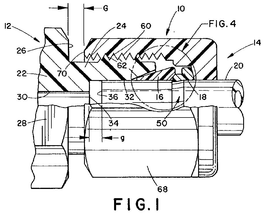
- Figures 1 and 4 generally show the overall arrangement of a tube fitting 10 which is particularly intended for use on resinous plastic tubing or other tubing having a degree of plasticity and relatively high lubricity. While the tube fitting 10 could have a variety of specific configurations, it is shown generally as comprising a main, male body component 12 and a female nut component 14 which cooperate to confine first and second ferrule members 16 and 18 into position about a tube 20.
- the body component 12 is molded from a suitable resinous plastic material such as PFA (perfluoroalkylvinylether), tetrafluoroethylene or nylon.
- the body component 12 comprises a main body section 22 and an outwardly extending portion 24.
- a radially extending, circumferentially continuous shoulder 26 is formed at the junction between the main body section 22 and the outwardly extending portion 24.
- the main body section 22 could be part of a standard fitting, or it could be part of a associated structure such as a valve or the like.
- the portion of the main body section 22 which is adjacent the reduced diameter portion 24 is provided with a generally hexagonal configuration to provide wrench flats 28.
- a flow passageway 30 which has a cylindrical configuration and is of a diameter slightly less than the outer diameter of the tube 20 to which the fitting assembly is to be connected.
- a counterbore 32 is formed at the outer end of the passage 30 and is joined therewith by an end wall 34 which preferably lies in a plane perpendicular to the axis of passageway 30.
- the diameter of the counterbore 32 is desirably sized so as to closely but freely receive the end of the tube 20. Additionally, it is preferable for the purposes of the subject invention to have the end wall 36 of the tube cut perpendicular to the axis of the tube.
- the outermost end of the counterbore 32 is provided with a generally conically shaped or tapered cammimg mouth 38 which is formed, as illustrated, at a relatively shallow angle relative to the axis of the passageway 30.
- the ferrule member 16 is arranged to cooperate with the camming mouth 38 such that the ferrule is driven into sealing engagement with the exterior wall of the tube 20 and the surface of the camming mouth 38 during fitting make-up.
- the ferrule member 16 is preferably formed of a suitable resilient plastic material such as PFA tetrafluoroethylene or nylon and has a generally conical exterior surface 40 which is preferably of an angle only slightly less than the angle of the camming mouth 38.
- the nose portion 42 of the ferrule 16 is relatively blunt or slightly rounded as shown.
- the rear surface of the ferrule 16 is provided with a conically shaped counterbore or camming mouth portion 44 which, as will subsequently be described, functions to drive the nose portion 46 of the rear ferrule 18 radially inwardly during fitting make-up.
- the rear ferrule 18 has the previously memtioned nose portion 46 which as a tapered upper surface 48 adapted to engage the conical camming mouth 44 on the rear of the first or front ferrule 16.
- the nose portion 46 has a diameter at its innermost position which is less than the outer diameter of the tube 20. That is, the original, pre-make-up inner diameter of nose portion 46 is significantly less than the outer diameter of tube 20.
- the tube 20 is provided with a circumferentially extending recess 50 having the preferred configuration best shown in Figure 4.
- the forward end of the recess 50 has a circumferentially continuous radially extending wall 52 which is generally perpendicular to the axis of the tube.
- An inclined or tapered wall or surface 54 extends from the radial innermost portion of the wall 52 to the outer surface of the tube 20.
- the rear portion of ferrule 18 is relatively thick and heavy and as an inclined outer wall 56.
- the recess 50 is located a predetermined distance from the end wall 36 of the tube 20. As best shown in Figures 1 and 2, it will be seen that the recess 50 is located a distance such that when the fitting is in the finger-tight position a small gap g exists between the end wall 36 of tube 20 and the bottom wall 34 of the counterbore 32. This relationship is selected so that the distance g is slightly less or substantially equal to the distance that the tube is driven axially into the counterbore 32 during make-up.
- the female nut member 14 acts to drive the ferrules into each other and into the camming mouth 38 during fitting make-up. For this reason, the female nut member 14 is joined to the main body component 12 through cooperating respective threads 60, 62 respectively. Interiorly, the nut member 14 has an end wall 64 which is inclined generally at the same angle as the end wall 56 of the ferrule member 18. This relationship is clearly shown in Figure 4. Additionally, the nut member 14 has a stepped interior bore with a reduced diameter portion 66 which surrounds the back end of front ferrule 16, as well as ferrule member 18 to limit their outward movement during fitting make-up. Additionally, it should be noted that the diameter of the stepped counterbore 66 is substantially less than the internal diameter of the threads 60. This assures that disassembly can take place without interference between the maximum outer extent of the ferrules 16 and 18 in their final deformed condition and the threads 60.
- the exterior of the nut member is provided wit a generally hex-shaped configuration to provide wrench flats 68.
- the hex-shaped configuration on the nut member 14 corresponds to the hex-shaped configuration on the main fitting body 12.
- the various components of the fitting are dimensioned such that "g" is equal to or slightly less than "G”. This assures that when the fitting is fully made-up, tube end 36 bottoms against wall 34 as wall 70 engages wall 26. This engaged relationship is sown in Figure 3 which represents the fitting in a final made-up condition.
- the tubing and the ferrules are driven inwardly.
- the positive engagement between the ferrule 18 and the recess 50 which results from the actual snap engagement between the ferrule and the recess during preliminary assembly prior to make-up assures that the tubing and the ferrules are driven into their final located position without slippage between any of the components.
- the final made-up position of the components is apparent by the engagement of th two radially exteding surfaces 26, 70 on the main fitting body 12 and the nut member 14, respectively.
- a further visual indication of proper make-up is provided by virtue of the location of the hex surfaces 28, 68 respectively.
- these surfaces are related to the threads and the surfaces 16, 70, such that at make-up and simultaneously with engagement of the surfaces 26, 70, the hex surfaces 28, 68 are in exact alignment as illustrated in Figure 3. That is, the peaks of the respective hex-shapes are aligned.
- the total space enclosed by the conical surface or camming mouth 38 and the counterbore 66 in the female nut 14 is substantially equal to the total volume of the ferrule members 16 and 18.
- This relationship is illustrated in Figure 3. Note that when in the full made-up condition, the ferrules 16, 18 are totally enclosed in a chamber defined by the body component 12, the nut member 14 and the tube 20. Because of this relationship, there is no available space into which cold flow of the ferrules can take place. This assures that the compression sealing forces generated within the ferrules during make-up are maintained throughout the assembled life of the fitting.
Landscapes
- Engineering & Computer Science (AREA)
- General Engineering & Computer Science (AREA)
- Mechanical Engineering (AREA)
- Joints With Pressure Members (AREA)
- Lining Or Joining Of Plastics Or The Like (AREA)
- Non-Disconnectible Joints And Screw-Threaded Joints (AREA)
- Infusion, Injection, And Reservoir Apparatuses (AREA)
- Joints That Cut Off Fluids, And Hose Joints (AREA)
- Diaphragms For Electromechanical Transducers (AREA)
- Mechanical Coupling Of Light Guides (AREA)
Abstract
Description
- The subject invention is directed toward the art of tube fittings and, more particularly, to a tube fitting particularly suited for use with resinous plastic tubing having a high degree of lubricity.
- Although it is possible to use standard metal tube fittings for joining plastic tubing, the results achieved are generally somewhat less than desirable. In particular, the relatively high lubricity of the plastic tubing makes it difficult to grip an hold the tubing within the fitting. In addition, when it is desired to have a full, plastic system wherein the fittings are also plastic, the gripping problems are further compounded.
- Prior attempts at providing plastic fittings and fittings particularly suited for plastic tubing have taken a variety of different approaches. Often, to generate sufficient gripping forces and prevent tubing collapse, toothed collars and internal tubing sleeves have been used separately or in combination. The internal sleeve approach is undesirable since it tends to reduce the available flow area. Similarly, the toothed collars or ferrules often result in significant deformation and/or damage to the tubing.
- Another approach which as been used, comprises driving a tapered, split ferrule into a tapered can mouth formed about a tube receiving opening in a fitting body. With this prior arrangement there is no ready way to determine wen the fitting is properly made-up or to prevent tubing collapse due to over tightening.
- Many other fitting designs have been proposed for resinous plastic tube but they have generally suffered from one or more of the noted problems.
- The subject invention provides a tube fitting wherein the problems discussed above are overcome and secure gripping and holding of the tube is achieved with a simple and efficient structure. The invention is such that it can be used for either metal or plastic tubing. Likewise, for certain uses and environments the fitting itself can be formed from either metal or plastic.
- In accordance wit the subject invention, a tube fitting particularly suited for joining resinous plastic tubing is provided and comprises a fitting body having a flow passage which extends inwardly from an exterior face thereof. Surrounding the outer end of the flow passage is a counterbore which is sized to closely receive the end of the tubing to be joined with the fitting. A tapered camming mouth is formed about the outer end of the couterbore. Positioned about the tube for cooperation with the camming mouth is a first ferrule having a central opening to closely receive the end of the tube. An outer surface of the first ferrule is engageable with the camming mouth and is adapted to be cammed radially inwardly upon movement of the ferrule into the camming mouth. A second ferrule is also positioned on the tube and is located outwardly of the first ferrule. The second ferrule has a nose portion with an internal diameter less than the outer diameter of the tube. The nose portion is engaged with a groove preformed into the exterior of the tube prior to make-up of the tube fitting. Surfaces formed on the forward end of the second ferrule and the rear surface of the first ferrule cooperate to produce radial inward movement of the nose portion of the second ferrule when the second ferrule is driven axially toward the first ferrule. Fitting nut means are threaded to the fitting body and enclose the first and second ferrule members. The nut means are operable to produce driving movement of the ferrules into the camming mouth to produce radial inward movement of the ferrules while simultaneously driving the tube into the counterbore.
- Preferably, and in accordance with a more limited aspect of the invention, the nut means cooperates with the fitting body to define a chamber which encloses the first and second ferrules. The total volume of the ferrules is substantially equal to the volume of the chamber when the fitting is in a made-up condition.
- In accordance with a still further aspect of the invention, the nut means and the fitting body include externally visible stop and alignment surfaces which come into engagement upon proper make-up of the fitting. This arrangement reduces the likelihood that the fitting will be overtightened and provides a quick visual indication of proper fitting make-up. When used in conjunction with the controlled ferrule space or chamber, proper make-up is assured and the tube is always engaged with a predetermined amount of ferrule contact and pressure. Moreover, because the second or rear ferrule is snapped fitted into a preformed groove prior to make-up, tightening of the fitting nut produces positive predetermined movement of the second ferrule and tubing into the camming mouth. Slippage between the ferrules and the tubing is not possible.
- Accordingly, by use of the present invention there may be provided one or more of the following:
- i) a tube fitting particularly intended for plastic tubing and designed so that proper fitting make-up is assured;
- ii) a fitting of the type described wherein the pressure sealing and tube holding ferrules are positively driven together with the tube into a final located position which cannot vary irrespective of tube or ferrule lubricity or the like;
- iii) a fitting of the type described wherein the ferrules are confined in a chamber having a predetermined volume which is only slightly larger than the total volume of the ferrule so that cold flow of the ferrule material cannot take place after the fitting is properly made-up;
- iv) a fitting of the type described wherein the sealing and holding functions are subdivided between two separate ferrule elements which are positively driven to a desired final made-up position so that total uniformity in sealing and gripping pressure is achieved;
- v) a tube fitting of the type wherein the tube is snap fit into the fitting to provide both sound and tactile indication of proper assembly;
- vi) a fitting in which the fully assembled position is indicated by both closure of an externally visible gap and alignment of externally visible hexagonal surface;
- vii) a tube fitting of the type described wherein the tubing ends can be manually inserted into the loosely assembled fitting.
- The invention will now be described by way of example, with reference to the following description read in conjunction with the accompanying drawings wherein:
- Figure 1 is a side elevational view partially in cross-section showing a fitting formed in accordance with the preferred embodiment of the invention (In Figure 1 the components are shown in a "finger-tight" assembled relationship prior to the final tightening and "make-up" of the fitting):
- Figure 2 is an exploded pictorial view showing the tube end and the associated fitting ferrules;
- Figure 3 is a view similar to Figure 1 but showing the fitting components in a fully tightened, made-up relationship; and,
- Figure 4 is an enlarged view of the circled area of Figure 1.
- Referring more particularly to the drawings wherein the showings are for the purpose of illustrating a preferred embodiment of the invention only, and not for the purpose of limiting same, Figures 1 and 4 generally show the overall arrangement of a
tube fitting 10 which is particularly intended for use on resinous plastic tubing or other tubing having a degree of plasticity and relatively high lubricity. While thetube fitting 10 could have a variety of specific configurations, it is shown generally as comprising a main,male body component 12 and afemale nut component 14 which cooperate to confine first andsecond ferrule members tube 20. Preferably, and in accordance with the preferred embodiment of the invention, thebody component 12 is molded from a suitable resinous plastic material such as PFA (perfluoroalkylvinylether), tetrafluoroethylene or nylon. Thebody component 12 comprises amain body section 22 and an outwardly extendingportion 24. A radially extending, circumferentiallycontinuous shoulder 26 is formed at the junction between themain body section 22 and the outwardly extendingportion 24. It should be appreciated that themain body section 22 could be part of a standard fitting, or it could be part of a associated structure such as a valve or the like. Preferably, the portion of themain body section 22 which is adjacent the reduceddiameter portion 24 is provided with a generally hexagonal configuration to providewrench flats 28. - Extending axially inwardly from the outer end of the reduced
diameter portion 24 is aflow passageway 30 which has a cylindrical configuration and is of a diameter slightly less than the outer diameter of thetube 20 to which the fitting assembly is to be connected. Acounterbore 32 is formed at the outer end of thepassage 30 and is joined therewith by anend wall 34 which preferably lies in a plane perpendicular to the axis ofpassageway 30. The diameter of thecounterbore 32 is desirably sized so as to closely but freely receive the end of thetube 20. Additionally, it is preferable for the purposes of the subject invention to have theend wall 36 of the tube cut perpendicular to the axis of the tube. - As best illustrated in Figure 4, the outermost end of the
counterbore 32 is provided with a generally conically shaped ortapered cammimg mouth 38 which is formed, as illustrated, at a relatively shallow angle relative to the axis of thepassageway 30. Theferrule member 16 is arranged to cooperate with thecamming mouth 38 such that the ferrule is driven into sealing engagement with the exterior wall of thetube 20 and the surface of the cammingmouth 38 during fitting make-up. For this reason, theferrule member 16 is preferably formed of a suitable resilient plastic material such as PFA tetrafluoroethylene or nylon and has a generally conicalexterior surface 40 which is preferably of an angle only slightly less than the angle of thecamming mouth 38. This relationship is best shown in Figure 4 wherein the various components are shown in a finger-tight assembled position. Preferably, thenose portion 42 of theferrule 16 is relatively blunt or slightly rounded as shown. The rear surface of theferrule 16 is provided with a conically shaped counterbore orcamming mouth portion 44 which, as will subsequently be described, functions to drive thenose portion 46 of therear ferrule 18 radially inwardly during fitting make-up. - The arrangement of
rear ferrule 18 and its relatioship to thetube 20 and thefront ferrule 16 is particularly important to the subject invention. In this regard, therear ferrule 18 has the previouslymemtioned nose portion 46 which as a taperedupper surface 48 adapted to engage theconical camming mouth 44 on the rear of the first orfront ferrule 16. In addition, thenose portion 46 has a diameter at its innermost position which is less than the outer diameter of thetube 20. That is, the original, pre-make-up inner diameter ofnose portion 46 is significantly less than the outer diameter oftube 20. In addition, thetube 20 is provided with a circumferentially extendingrecess 50 having the preferred configuration best shown in Figure 4. More particularly, the forward end of therecess 50 has a circumferentially continuousradially extending wall 52 which is generally perpendicular to the axis of the tube. An inclined or tapered wall orsurface 54 extends from the radial innermost portion of thewall 52 to the outer surface of thetube 20. The rear portion offerrule 18 is relatively thick and heavy and as an inclinedouter wall 56. - The
recess 50 is located a predetermined distance from theend wall 36 of thetube 20. As best shown in Figures 1 and 2, it will be seen that therecess 50 is located a distance such that when the fitting is in the finger-tight position a small gap g exists between theend wall 36 oftube 20 and thebottom wall 34 of thecounterbore 32. This relationship is selected so that the distance g is slightly less or substantially equal to the distance that the tube is driven axially into thecounterbore 32 during make-up. - As previously mentioned, the
female nut member 14 acts to drive the ferrules into each other and into thecamming mouth 38 during fitting make-up. For this reason, thefemale nut member 14 is joined to themain body component 12 through cooperatingrespective threads nut member 14 has anend wall 64 which is inclined generally at the same angle as theend wall 56 of theferrule member 18. This relationship is clearly shown in Figure 4. Additionally, thenut member 14 has a stepped interior bore with a reduceddiameter portion 66 which surrounds the back end offront ferrule 16, as well asferrule member 18 to limit their outward movement during fitting make-up. Additionally, it should be noted that the diameter of the steppedcounterbore 66 is substantially less than the internal diameter of thethreads 60. This assures that disassembly can take place without interference between the maximum outer extent of theferrules threads 60. - In order to allow the
female nut member 14 to be driven to the final made-up position show in Figure 3, the exterior of the nut member is provided wit a generally hex-shaped configuration to providewrench flats 68. Preferably, and in accordance with an aspect of the invention, the hex-shaped configuration on thenut member 14 corresponds to the hex-shaped configuration on the mainfitting body 12. The various components of the fitting are dimensioned such that "g" is equal to or slightly less than "G". This assures that when the fitting is fully made-up,tube end 36 bottoms againstwall 34 aswall 70 engageswall 26. This engaged relationship is sown in Figure 3 which represents the fitting in a final made-up condition. As the fitting is being made-up, the tubing and the ferrules are driven inwardly. The positive engagement between theferrule 18 and therecess 50 which results from the actual snap engagement between the ferrule and the recess during preliminary assembly prior to make-up assures that the tubing and the ferrules are driven into their final located position without slippage between any of the components. Additionally, the final made-up position of the components is apparent by the engagement of th two radially exteding surfaces 26, 70 on the mainfitting body 12 and thenut member 14, respectively. A further visual indication of proper make-up is provided by virtue of the location of the hex surfaces 28, 68 respectively. That is, these surfaces are related to the threads and thesurfaces surfaces - In accordance with a further aspect of the invention, the total space enclosed by the conical surface or
camming mouth 38 and thecounterbore 66 in thefemale nut 14 is substantially equal to the total volume of theferrule members ferrules body component 12, thenut member 14 and thetube 20. Because of this relationship, there is no available space into which cold flow of the ferrules can take place. This assures that the compression sealing forces generated within the ferrules during make-up are maintained throughout the assembled life of the fitting. - The invention has been described with reference to preferred and alternate embodiments. Obviously, modifications and alterations will occur to others upon the reading and understanding of this specification. It is intended to include all such modifications and alterations insofar as they come within the scope of the appended claims or the equivalents thereof.
Claims (17)
- A tube fitting particularly suited for joining resinous plastic tubing and comprising:
a fitting body (12) having a flow passage (30) extending inwardly from an exterior face thereof;
a counterbore (32) surrounding the outer end of said passage and sized to closely receive the end of a tube to be joined with said fitting, and a tapered camming mouth (38) formed about the outer end of said counterbore (32)
a first ferrule (16) having a central opening to closely receive the end of said tube and an outer surface (40) engageable with said camming mouth (38) and adapted to be cammed radially inwardly upon movement of said ferrule (16) into said camming mouth (38);
a second ferrule (18) having a central opening to closely receive the end of said tube and a reduced diameter nose portion (46) adapted to be snapped into a groove (50) formed in the exterior of said tube prior to make-up of said fitting;
surfaces formed on the forward exterior of said second ferrule (18) and the rear surface of said first ferrule (16) co-operate to produce radial inward movement of the nose portion (46) of said second ferrule (18) when said second ferrule (18) is driven axially toward said first ferrule (16); and
fitting nut means (14) threaded to said fitting body (12) and enclosing said first and second ferrule members (16,18), said nut means (14) operable to produce driving movement of said first and second ferrules (16,18) into said camming mouth to cause radial inward movement of said ferrules (16,18) while driving said tube (20) into said counterbore. - A fitting as claimed in claim 1, wherein said nut means (14) is threadedly joined to the exterior of said fitting body (12).
- A fitting as claimed in claim 1 or 2, wherein said first and second ferrule members (16,18) have a volume which is only slightly less than the space in which they are confined by said nut means (14) and said fitting body (12) when said fitting is in a made-up condition.
- A fitting as claimed in claim 1, 2 or 3, wherein said first ferrule (16) has a conical recess (44) facing said second ferrule (18), said conical recess receiving said reduced diameter nose portion (46) and producing radially inward deflection thereof during movement of said second ferrule (18) toward said first ferrule (16).
- A fitting as claimed in any one of the preceding claims, wherein said nut means (14) and said body (12) have externally visible stop surfaces which come into engagement when said fitting is properly made-up.
- A fitting as claimed in claim 5, wherein said body and said nut means each have externally visible wrench surfaces which come into alignment when said stop surfaces come into engagement.
- A fitting as claimed in any one of the preceding claims, wherein said nut means (14) comprises a nut member having internal threads and an internal counterbore which encloses said first and second ferrules (16,18) when said fitting is in a made-up condition, said internal counterbore in said nut member having a diameter which is substantially less than the diameter of said internal threads.
- A fitting as claimed in any one of the preceding claims, wherein said counterbore surrounding the outer end of the passage in said body terminates in a transverse end wall, said end wall located to limit movement of said tube inwardly of said body during make-up of said fitting.
- A tube fitting for joining resinous plastic tubing and comprising:
a body member (12) having a tube receiving opening with a conically shaped camming mouth (38) facing outwardly of said opening;
a tube (20) closely received in said opening;
a first ferrule member (16) slidably received on said tube and having an exterior surface which faces said camming mouth (38) and has a conical shape generally corresponding to the shape of said camming mouth;
a second ferrule member (18) slidably received on said tube (20) at a location outwardly of said opening and said first ferrule (16), said second ferrule member (18) having a nose portion (46) which engages the first ferrule (16) adjacent said tube, said nose portion (46) being circumferentially continuous about said tube;
said tube including a recess (50) formed circumferentially thereof prior to association of said tube with said fitting, the location of said recess corresponding to the predetermined desired axial location of the nose portion (46) of said second ferrule (18) when said fitting is in a made-up condition;
said nose portion (46) of said second ferrule (18) encircling said tube (20) and being engaged in said recess (50) in axial driving engagement with said tube prior to make-up of said fitting; and,
nut means (14) threadedly engaged with said body for driving said first and second ferrules (16,18) into said camming mouth. - A tube fitting as claimed in claim 9, wherein said second ferrule (18) has an internal diameter adjacent said nose portion (46) which is less than the external diameter of said tube, said second ferrule (18) being interference fitted on said tube with said nose portion (46) engaged in said recess (50) prior to make-up of said fitting.
- A tube fitting as claimed in claim 9 or 10, wherein said nut means (14) is threadedly engaged with the exterior of said body (12) and co-operating therewith to define a chamber which encloses said first and second ferrules (16,18), the total volume of said ferrules being substantially equal to the volume of said chamber when said fitting is in a made-up condition.
- A tube fitting as claimed in any one of claims 9 to 11, wherein each of said first and second ferrules (16,18) are formed of a resinous plastic material.
- A tube fitting as claimed in any one of claims 9 to 12, wherein said first ferrule (16) includes a conical camming surface (44) engaging the nose portion (46) of said second ferrule (18) for driving said nose portion (46) radially inward when said second ferrule (18) is moved toward said first ferrule (16) during make-up of said fitting.
- A tube fitting as claimed in any one of claims 9 to 13, wherein said tube receiving opening terminates in a transversely extending end wall located to define a limit of inward movement of said tube during make-up of said fitting.
- A tube fitting as claimed in claim 14, wherein said end wall is located to be engaged by the end of said tube prior to completion of make-up of said fitting.
- A tube fitting as claimed in any one of claims 9 to 15, wherein said nut means and said body have externally visible stop surfaces which come into engagement when said fitting is properly made-up.
- A tube fitting as claimed in claim 14, wherein said nut means and said body each have externally visible wrench surfaces which come into alignment when said stop surfaces come into engagement.
Priority Applications (1)
| Application Number | Priority Date | Filing Date | Title |
|---|---|---|---|
| AT91309960T ATE97730T1 (en) | 1990-10-30 | 1991-10-29 | PIPE CONNECTION. |
Applications Claiming Priority (2)
| Application Number | Priority Date | Filing Date | Title |
|---|---|---|---|
| US07/605,923 US5074599A (en) | 1990-10-30 | 1990-10-30 | Tube fitting |
| US605923 | 1995-10-27 |
Publications (2)
| Publication Number | Publication Date |
|---|---|
| EP0484091A1 true EP0484091A1 (en) | 1992-05-06 |
| EP0484091B1 EP0484091B1 (en) | 1993-11-24 |
Family
ID=24425774
Family Applications (1)
| Application Number | Title | Priority Date | Filing Date |
|---|---|---|---|
| EP91309960A Expired - Lifetime EP0484091B1 (en) | 1990-10-30 | 1991-10-29 | Tube fitting |
Country Status (9)
| Country | Link |
|---|---|
| US (1) | US5074599A (en) |
| EP (1) | EP0484091B1 (en) |
| JP (1) | JPH05149491A (en) |
| KR (1) | KR920008397A (en) |
| CN (1) | CN1061268A (en) |
| AT (1) | ATE97730T1 (en) |
| AU (1) | AU636554B2 (en) |
| CA (1) | CA2054142A1 (en) |
| DE (1) | DE69100681T2 (en) |
Cited By (6)
| Publication number | Priority date | Publication date | Assignee | Title |
|---|---|---|---|---|
| US6629708B2 (en) | 1997-04-15 | 2003-10-07 | Swagelok Company | Ferrule with relief to reduce galling |
| US7100949B2 (en) | 1997-04-15 | 2006-09-05 | Swagelok Company | Ferrule with relief to reduce galling |
| US10024468B2 (en) | 2014-05-09 | 2018-07-17 | Swagelok Company | Conduit fitting with components adapted for facilitating assembly |
| US10100955B2 (en) | 1997-04-15 | 2018-10-16 | Swagelok Company | Advanced geomerty ferrule |
| US10215315B2 (en) | 2008-09-05 | 2019-02-26 | Parker-Hannifin Corporation | Tube compression fitting and flared fitting used with connection body and method of making same |
| US10584814B2 (en) | 2016-03-23 | 2020-03-10 | Swagelok Company | Conduit fitting with stroke resisting features |
Families Citing this family (68)
| Publication number | Priority date | Publication date | Assignee | Title |
|---|---|---|---|---|
| DE4038539C1 (en) * | 1990-12-03 | 1992-04-30 | Parker-Ermeto Gmbh, 4800 Bielefeld, De | |
| JP2587449Y2 (en) * | 1993-08-04 | 1998-12-16 | 日曹エンジニアリング株式会社 | Piping joint mechanism |
| AU657665B3 (en) * | 1994-07-12 | 1995-03-16 | Alprene S.A.S. Di Baldussi Ezio & C. | An axial coupling joint for plastic pipes |
| US5749179A (en) * | 1995-06-02 | 1998-05-12 | Component Hardware Group, Inc. | Wall bracket for a pre-rinse assembly |
| US5907966A (en) * | 1996-06-19 | 1999-06-01 | Moore; Boyd B. | Rolled-formed seat and retainer for a fluid-tight ferrule seal on a rigid metal tube which is harder than the ferrule, method and apparatus |
| US5725259A (en) * | 1996-12-19 | 1998-03-10 | Dials; Carroll P. | Conduit coupling |
| JP3871428B2 (en) * | 1998-02-16 | 2007-01-24 | シーケーディ株式会社 | Weld-less fitting |
| GB2353342A (en) * | 1999-08-17 | 2001-02-21 | Michael Douglas Seymour | Method of forming a connection between a tube and a fitting |
| US6640457B2 (en) | 1999-09-13 | 2003-11-04 | Swagelok Company | Intrinsic gauging for tube fittings |
| US7194817B2 (en) * | 1999-09-13 | 2007-03-27 | Swagelok Company | Intrinsic gauging for tube fittings |
| US6279242B1 (en) | 1999-09-13 | 2001-08-28 | Swagelok Company | Intrinsic gauging for tube fittings |
| US6527304B1 (en) * | 2000-02-17 | 2003-03-04 | Ford Global Technologies, Inc. | Brake tube connector |
| US7407196B2 (en) | 2003-08-06 | 2008-08-05 | Swagelok Company | Tube fitting with separable tube gripping device |
| US7066496B2 (en) | 2001-02-06 | 2006-06-27 | Swagelok Company | Fitting with separable gripping device for pipe and tube |
| US7416225B2 (en) | 2001-02-06 | 2008-08-26 | Swagelok Company | Fitting for metal pipe and tubing |
| JP4128079B2 (en) | 2001-02-06 | 2008-07-30 | スウエイジロク・カンパニー | Pipe fittings for stainless steel pipes |
| US7055870B2 (en) * | 2001-07-12 | 2006-06-06 | Hayes Jr Frank F | Molded flare assembly |
| US6851729B2 (en) | 2001-12-07 | 2005-02-08 | Parker-Hannifin Corporation | Tube fitting for medium pressure applications |
| JP2003232474A (en) * | 2002-02-08 | 2003-08-22 | Nasco Fitting Kk | Pipe joint |
| US6702258B1 (en) * | 2002-06-10 | 2004-03-09 | F. Pettinaroli, S.P.A. | Universal ball valve assembly |
| WO2003106992A2 (en) * | 2002-06-17 | 2003-12-24 | Swagelok Company | Ultrasonic testing of fitting assembly |
| DE10233862B4 (en) * | 2002-07-19 | 2007-06-06 | Eisele Pneumatics Gmbh | A system for connecting a tubular conduit to a connection device, method for machining an end portion of the tubular conduit and associated tool |
| US6764109B2 (en) * | 2002-07-31 | 2004-07-20 | H. Gary Richardson | Hammer union and seal therefor |
| US6899358B2 (en) | 2002-11-13 | 2005-05-31 | H. Gary Richardson | Hammer union and seal therefor |
| US7032935B1 (en) * | 2003-04-08 | 2006-04-25 | David Levy | Self energizing connector |
| CA2482505C (en) * | 2003-09-25 | 2010-11-23 | Philmac Pty Ltd | A collet for pipe coupling |
| CA2543573A1 (en) * | 2003-11-03 | 2005-05-12 | Swagelok Company | Fitting for metal pipe and tubing |
| US7784837B2 (en) | 2003-11-03 | 2010-08-31 | Swagelok Company | Fitting for metal pipe and tubing |
| TW200602577A (en) | 2004-04-22 | 2006-01-16 | Swagelok Co | Fitting for tube and pipe |
| US7497483B2 (en) | 2004-04-22 | 2009-03-03 | Swagelok Company | Fitting for tube and pipe with cartridge |
| JP3847312B2 (en) * | 2004-09-29 | 2006-11-22 | 東尾メック株式会社 | Pipe fitting |
| CA2618331A1 (en) * | 2005-07-04 | 2007-01-11 | Nippon Flex Co., Ltd. | Connector for connecting hoses |
| EP2489912B1 (en) | 2006-01-13 | 2016-03-09 | Swagelok Company | Fitting for tube or pipe |
| JP4007391B2 (en) * | 2006-03-31 | 2007-11-14 | ダイキン工業株式会社 | Biting-in type pipe connection structure, pipe joint, valve, closing valve, refrigeration cycle apparatus, and hot water supply apparatus |
| JP2010509548A (en) * | 2006-11-02 | 2010-03-25 | スウエイジロク・カンパニー | Torque tightened fitting |
| US7686352B2 (en) * | 2007-03-05 | 2010-03-30 | Brass Craft Manufacturing Company | Tubing for a plumbing connection |
| US9677698B2 (en) * | 2007-06-12 | 2017-06-13 | Cameron International Corporation | Connector system and method |
| JP5457348B2 (en) * | 2007-07-27 | 2014-04-02 | スウエイジロク・カンパニー | Tapered nut for pipe or pipe fitting with centering |
| DE112008002088T5 (en) | 2007-08-03 | 2010-09-09 | Swagelok Company, Solon | Ring clamp connection with torque-based mounting |
| JP5984393B2 (en) * | 2008-12-10 | 2016-09-06 | スウエイジロク・カンパニー | Ferrule assembly for conduit fitting |
| CN105065807B (en) | 2009-02-20 | 2018-04-10 | 斯瓦戈洛克公司 | Conduit fittings with torque collar |
| US8960728B2 (en) | 2009-02-20 | 2015-02-24 | Swagelok Company | Conduit fitting with split torque collar |
| CN105402516B (en) * | 2009-02-20 | 2018-11-06 | 斯瓦戈洛克公司 | Pre- swaging apparatus with pivotable clip clamping apparatus |
| WO2010129261A1 (en) | 2009-04-27 | 2010-11-11 | Swagelok Company | Tapered drive nut for conduit fitting |
| DE202009019091U1 (en) | 2009-12-21 | 2016-05-23 | Agilent Technologies, Inc. - A Delaware Corporation - | Fitting element with front insert |
| CN102792082B (en) | 2009-12-21 | 2015-03-11 | 安捷伦科技有限公司 | Fitting element with front side seal |
| KR100987334B1 (en) * | 2010-02-11 | 2010-10-12 | 주식회사 비엠티 | Tube fitting structure which is possible to check the tightening amount |
| US9803782B2 (en) | 2010-05-03 | 2017-10-31 | Agilent Technologies, Inc. | Fitting element with hydraulic grip force element |
| GB2481195B (en) | 2010-06-14 | 2016-01-06 | Agilent Technologies Inc | Fitting element with grip force distributor |
| EP2591261B1 (en) | 2010-07-09 | 2019-10-23 | Swagelok Company | Conduit fitting with flexible torque collar |
| GB2482175B (en) | 2010-07-23 | 2016-01-13 | Agilent Technologies Inc | Fitting element with bio-compatible sealing |
| GB2482488B (en) | 2010-08-03 | 2016-01-13 | Agilent Technologies Inc | Fitting coupler for planar fluid conduit |
| GB2486641A (en) | 2010-12-20 | 2012-06-27 | Agilent Technologies Inc | A sealed fluidic component comprising two PAEK materials |
| CH705381A1 (en) * | 2011-08-15 | 2013-02-15 | Moeller Medical Gmbh | Tube comprising metal shell with plastic inlay for use in low and high pressure applications, particularly as HPLC column. |
| US20130193683A1 (en) * | 2012-01-26 | 2013-08-01 | Haskel International Incorporated | High pressure fitting |
| CN102620079A (en) * | 2012-03-27 | 2012-08-01 | 河北省景县景渤石油机械有限公司 | Fire resistant rubber pipe assembly |
| WO2014093986A2 (en) * | 2012-12-14 | 2014-06-19 | Ssp Fittings Corp. | System including cartridge, catridge feed system, pre-swaging assembly, tube bender, cutting and deburring station, and air blower/ vacuum chip collector |
| CN103016863B (en) * | 2012-12-19 | 2015-01-07 | 中联重科股份有限公司 | Pipeline connecting structure and hydraulic pipeline |
| US9086176B2 (en) * | 2013-03-18 | 2015-07-21 | Wen Sheng Fu Co. Ltd. | Valve structure |
| EP3011214B1 (en) | 2013-06-19 | 2019-05-22 | Parker-Hannificn Corporation | High strength flexible ferrule |
| US20160221014A1 (en) * | 2013-09-25 | 2016-08-04 | United Technologies Corporation | Simplified cold spray nozzle and gun |
| WO2015187958A1 (en) | 2014-06-04 | 2015-12-10 | Parker-Hannifin Corporation | Compression fitting with torque nut |
| US11067467B2 (en) * | 2015-09-08 | 2021-07-20 | Mécanique Analytique Inc. | Fitting assembly with leak detection for analytical systems |
| CN106894448A (en) * | 2017-02-09 | 2017-06-27 | 中铁隧道勘测设计院有限公司 | For the final joints structure form of immersed tube tunnel |
| US10317001B2 (en) | 2017-03-15 | 2019-06-11 | Tylok International, Inc. | Axial swaged fitting |
| CN110220049B (en) * | 2019-07-11 | 2023-08-22 | 芜湖泰和管业股份有限公司 | Composite metal bellows with hard seal joint |
| US11204114B2 (en) | 2019-11-22 | 2021-12-21 | Trinity Bay Equipment Holdings, LLC | Reusable pipe fitting systems and methods |
| CN113389720A (en) * | 2021-05-27 | 2021-09-14 | 中国十七冶集团有限公司 | Conveniently-installed triple control pump and use method thereof |
Citations (4)
| Publication number | Priority date | Publication date | Assignee | Title |
|---|---|---|---|---|
| GB811384A (en) * | 1956-08-16 | 1959-04-02 | High Pressure Components Ltd | Improvements in or relating to pipe joints or pipe couplings |
| US3501177A (en) * | 1968-10-14 | 1970-03-17 | Arthur W Jacobs | Tube coupling |
| FR2136416A5 (en) * | 1971-04-15 | 1972-12-22 | Crawford Fitting Co | |
| US3977708A (en) * | 1975-09-11 | 1976-08-31 | Fluoroware, Inc. | Plastic tube fitting and joint |
Family Cites Families (12)
| Publication number | Priority date | Publication date | Assignee | Title |
|---|---|---|---|---|
| FR794525A (en) * | 1934-09-10 | 1936-02-19 | Improvements to pipe connections | |
| US2484815A (en) * | 1947-08-15 | 1949-10-18 | Crawford Fitting Co | Tube coupling |
| US3103373A (en) * | 1961-06-29 | 1963-09-10 | Crawford Fitting Co | Controlled phase sequential gripping device |
| US3402949A (en) * | 1966-06-06 | 1968-09-24 | Hoke Mfg Company Inc | Stepped connector body |
| US3445128A (en) * | 1967-04-10 | 1969-05-20 | Hoke Inc | Tube coupling having dual ferrule gripping elements with stop means |
| US3584900A (en) * | 1968-09-18 | 1971-06-15 | Sno Trik Co | High-pressure sealing and gripping device |
| US3695647A (en) * | 1970-07-16 | 1972-10-03 | Hoke Inc | Pipe coupling |
| JPS5025649B1 (en) * | 1970-12-05 | 1975-08-26 | ||
| US4500118A (en) * | 1982-12-30 | 1985-02-19 | Colder Products Company | Fitting apparatus for soft tubing |
| US4799717A (en) * | 1987-09-02 | 1989-01-24 | Mace Corporation | Torque lock fitting arrangement |
| US4826218A (en) * | 1987-12-10 | 1989-05-02 | Crawford Fitting Co. | Coupling device for heavy-walled tubular members |
| US4871196A (en) * | 1988-02-01 | 1989-10-03 | Mace Corporation | Double shield fitting |
-
1990
- 1990-10-30 US US07/605,923 patent/US5074599A/en not_active Expired - Lifetime
-
1991
- 1991-10-28 CA CA002054142A patent/CA2054142A1/en not_active Abandoned
- 1991-10-29 DE DE91309960T patent/DE69100681T2/en not_active Expired - Fee Related
- 1991-10-29 EP EP91309960A patent/EP0484091B1/en not_active Expired - Lifetime
- 1991-10-29 AU AU86848/91A patent/AU636554B2/en not_active Ceased
- 1991-10-29 AT AT91309960T patent/ATE97730T1/en not_active IP Right Cessation
- 1991-10-30 KR KR1019910019130A patent/KR920008397A/en not_active Application Discontinuation
- 1991-10-30 JP JP3284799A patent/JPH05149491A/en active Pending
- 1991-10-30 CN CN91109969A patent/CN1061268A/en active Pending
Patent Citations (4)
| Publication number | Priority date | Publication date | Assignee | Title |
|---|---|---|---|---|
| GB811384A (en) * | 1956-08-16 | 1959-04-02 | High Pressure Components Ltd | Improvements in or relating to pipe joints or pipe couplings |
| US3501177A (en) * | 1968-10-14 | 1970-03-17 | Arthur W Jacobs | Tube coupling |
| FR2136416A5 (en) * | 1971-04-15 | 1972-12-22 | Crawford Fitting Co | |
| US3977708A (en) * | 1975-09-11 | 1976-08-31 | Fluoroware, Inc. | Plastic tube fitting and joint |
Cited By (12)
| Publication number | Priority date | Publication date | Assignee | Title |
|---|---|---|---|---|
| US6629708B2 (en) | 1997-04-15 | 2003-10-07 | Swagelok Company | Ferrule with relief to reduce galling |
| US7100949B2 (en) | 1997-04-15 | 2006-09-05 | Swagelok Company | Ferrule with relief to reduce galling |
| US7240929B2 (en) | 1997-04-15 | 2007-07-10 | Swagelok Company | Ferrule with plural inner diameters |
| US7367595B2 (en) | 1997-04-15 | 2008-05-06 | Swagelok Company | Ferrule having convex interior wall portion |
| US10100955B2 (en) | 1997-04-15 | 2018-10-16 | Swagelok Company | Advanced geomerty ferrule |
| USD884130S1 (en) | 1997-04-15 | 2020-05-12 | Swagelok Company | Back ferrule |
| US10215315B2 (en) | 2008-09-05 | 2019-02-26 | Parker-Hannifin Corporation | Tube compression fitting and flared fitting used with connection body and method of making same |
| US10024468B2 (en) | 2014-05-09 | 2018-07-17 | Swagelok Company | Conduit fitting with components adapted for facilitating assembly |
| US11079046B2 (en) | 2014-05-09 | 2021-08-03 | Swagelok Company | Conduit fitting with components adapted for facilitating assembly |
| US12072044B2 (en) | 2014-05-09 | 2024-08-27 | Swagelok Company | Conduit fitting with components adapted for facilitating assembly |
| US10584814B2 (en) | 2016-03-23 | 2020-03-10 | Swagelok Company | Conduit fitting with stroke resisting features |
| US11009158B2 (en) | 2016-03-23 | 2021-05-18 | Swagelok Company | Conduit fitting with stroke resisting features |
Also Published As
| Publication number | Publication date |
|---|---|
| AU636554B2 (en) | 1993-04-29 |
| ATE97730T1 (en) | 1993-12-15 |
| US5074599A (en) | 1991-12-24 |
| EP0484091B1 (en) | 1993-11-24 |
| JPH05149491A (en) | 1993-06-15 |
| DE69100681T2 (en) | 1994-03-17 |
| AU8684891A (en) | 1992-05-07 |
| CA2054142A1 (en) | 1992-05-01 |
| KR920008397A (en) | 1992-05-27 |
| CN1061268A (en) | 1992-05-20 |
| DE69100681D1 (en) | 1994-01-05 |
Similar Documents
| Publication | Publication Date | Title |
|---|---|---|
| EP0484091B1 (en) | Tube fitting | |
| US4674775A (en) | Coupling for corrugated conduit | |
| US5364135A (en) | End fitting for flexible conduit | |
| US4188051A (en) | Tube coupling | |
| US7806443B1 (en) | Method and apparatus for connecting air conditioning coolant lines | |
| US4637636A (en) | Tube couplings | |
| US4848802A (en) | Tubing connector assembly | |
| US5240291A (en) | Sanitary hose coupler | |
| CA2189596A1 (en) | Valve Connector System for Plastic Pipe | |
| US4302036A (en) | Tube coupling | |
| EP1065425A3 (en) | Tube joint | |
| US4586733A (en) | Adapter coupling for liquid chromatography device | |
| EP0112015A1 (en) | Couplings for tubes and other fluid handling components | |
| US20080048440A1 (en) | Direct port connection for tubes | |
| EP0898676B1 (en) | Integral pup joint | |
| US4243254A (en) | Slip fit type tubing coupling | |
| US2570477A (en) | Hose coupling | |
| US5141263A (en) | Fluid line connector fitting with longitudinal release mechanism | |
| US6866305B2 (en) | Pipe fitting having strengthened starter threads | |
| US6991268B2 (en) | Pipe fitting having over-sized strengthened starter threads | |
| US7900974B1 (en) | Method and apparatus for connecting air conditioning coolant lines | |
| US3498646A (en) | Tube coupling | |
| US20070001448A1 (en) | Sanitary hose couplers | |
| US3618990A (en) | Tube coupling | |
| US20040045447A1 (en) | Sanitary hose couplers |
Legal Events
| Date | Code | Title | Description |
|---|---|---|---|
| PUAI | Public reference made under article 153(3) epc to a published international application that has entered the european phase |
Free format text: ORIGINAL CODE: 0009012 |
|
| AK | Designated contracting states |
Kind code of ref document: A1 Designated state(s): AT BE CH DE DK ES FR GB IT LI NL SE |
|
| 17P | Request for examination filed |
Effective date: 19920626 |
|
| 17Q | First examination report despatched |
Effective date: 19930119 |
|
| GRAA | (expected) grant |
Free format text: ORIGINAL CODE: 0009210 |
|
| AK | Designated contracting states |
Kind code of ref document: B1 Designated state(s): AT BE CH DE DK ES FR GB IT LI NL SE |
|
| PG25 | Lapsed in a contracting state [announced via postgrant information from national office to epo] |
Ref country code: CH Effective date: 19931124 Ref country code: IT Free format text: LAPSE BECAUSE OF FAILURE TO SUBMIT A TRANSLATION OF THE DESCRIPTION OR TO PAY THE FEE WITHIN THE PRE;WARNING: LAPSES OF ITALIAN PATENTS WITH EFFECTIVE DATE BEFORE 2007 MAY HAVE OCCURRED AT ANY TIME BEFORE 2007. THE CORRECT EFFECTIVE DATE MAY BE DIFFERENT FROM THE ONE RECORDED.SCRIBED TIME-LIMIT Effective date: 19931124 Ref country code: BE Effective date: 19931124 Ref country code: ES Free format text: THE PATENT HAS BEEN ANNULLED BY A DECISION OF A NATIONAL AUTHORITY Effective date: 19931124 Ref country code: LI Effective date: 19931124 Ref country code: AT Effective date: 19931124 Ref country code: SE Effective date: 19931124 Ref country code: NL Effective date: 19931124 Ref country code: DK Effective date: 19931124 |
|
| REF | Corresponds to: |
Ref document number: 97730 Country of ref document: AT Date of ref document: 19931215 Kind code of ref document: T |
|
| ET | Fr: translation filed | ||
| REF | Corresponds to: |
Ref document number: 69100681 Country of ref document: DE Date of ref document: 19940105 |
|
| REG | Reference to a national code |
Ref country code: CH Ref legal event code: PL |
|
| NLV1 | Nl: lapsed or annulled due to failure to fulfill the requirements of art. 29p and 29m of the patents act | ||
| PLBE | No opposition filed within time limit |
Free format text: ORIGINAL CODE: 0009261 |
|
| STAA | Information on the status of an ep patent application or granted ep patent |
Free format text: STATUS: NO OPPOSITION FILED WITHIN TIME LIMIT |
|
| 26N | No opposition filed | ||
| PGFP | Annual fee paid to national office [announced via postgrant information from national office to epo] |
Ref country code: GB Payment date: 19950918 Year of fee payment: 5 |
|
| PGFP | Annual fee paid to national office [announced via postgrant information from national office to epo] |
Ref country code: FR Payment date: 19951020 Year of fee payment: 5 |
|
| PGFP | Annual fee paid to national office [announced via postgrant information from national office to epo] |
Ref country code: DE Payment date: 19951027 Year of fee payment: 5 |
|
| PG25 | Lapsed in a contracting state [announced via postgrant information from national office to epo] |
Ref country code: GB Effective date: 19961029 |
|
| GBPC | Gb: european patent ceased through non-payment of renewal fee |
Effective date: 19961029 |
|
| PG25 | Lapsed in a contracting state [announced via postgrant information from national office to epo] |
Ref country code: FR Effective date: 19970630 |
|
| PG25 | Lapsed in a contracting state [announced via postgrant information from national office to epo] |
Ref country code: DE Effective date: 19970701 |
|
| REG | Reference to a national code |
Ref country code: FR Ref legal event code: ST |