EP0484002B1 - Child-resistant trigger sprayer - Google Patents
Child-resistant trigger sprayer Download PDFInfo
- Publication number
- EP0484002B1 EP0484002B1 EP91309488A EP91309488A EP0484002B1 EP 0484002 B1 EP0484002 B1 EP 0484002B1 EP 91309488 A EP91309488 A EP 91309488A EP 91309488 A EP91309488 A EP 91309488A EP 0484002 B1 EP0484002 B1 EP 0484002B1
- Authority
- EP
- European Patent Office
- Prior art keywords
- latch
- latch means
- pump
- projection
- trigger
- Prior art date
- Legal status (The legal status is an assumption and is not a legal conclusion. Google has not performed a legal analysis and makes no representation as to the accuracy of the status listed.)
- Expired - Lifetime
Links
- 238000005086 pumping Methods 0.000 claims description 12
- 210000003811 finger Anatomy 0.000 description 5
- 210000005224 forefinger Anatomy 0.000 description 4
- 230000001419 dependent effect Effects 0.000 description 1
- 239000002917 insecticide Substances 0.000 description 1
- 230000002452 interceptive effect Effects 0.000 description 1
- 230000004048 modification Effects 0.000 description 1
- 238000012986 modification Methods 0.000 description 1
- 231100000614 poison Toxicity 0.000 description 1
- 230000007096 poisonous effect Effects 0.000 description 1
- 238000007789 sealing Methods 0.000 description 1
Images

Classifications
-
- B—PERFORMING OPERATIONS; TRANSPORTING
- B05—SPRAYING OR ATOMISING IN GENERAL; APPLYING FLUENT MATERIALS TO SURFACES, IN GENERAL
- B05B—SPRAYING APPARATUS; ATOMISING APPARATUS; NOZZLES
- B05B11/00—Single-unit hand-held apparatus in which flow of contents is produced by the muscular force of the operator at the moment of use
- B05B11/01—Single-unit hand-held apparatus in which flow of contents is produced by the muscular force of the operator at the moment of use characterised by the means producing the flow
- B05B11/10—Pump arrangements for transferring the contents from the container to a pump chamber by a sucking effect and forcing the contents out through the dispensing nozzle
- B05B11/1001—Piston pumps
- B05B11/1009—Piston pumps actuated by a lever
- B05B11/1011—Piston pumps actuated by a lever without substantial movement of the nozzle in the direction of the pressure stroke
-
- B—PERFORMING OPERATIONS; TRANSPORTING
- B05—SPRAYING OR ATOMISING IN GENERAL; APPLYING FLUENT MATERIALS TO SURFACES, IN GENERAL
- B05B—SPRAYING APPARATUS; ATOMISING APPARATUS; NOZZLES
- B05B11/00—Single-unit hand-held apparatus in which flow of contents is produced by the muscular force of the operator at the moment of use
- B05B11/01—Single-unit hand-held apparatus in which flow of contents is produced by the muscular force of the operator at the moment of use characterised by the means producing the flow
- B05B11/10—Pump arrangements for transferring the contents from the container to a pump chamber by a sucking effect and forcing the contents out through the dispensing nozzle
- B05B11/1042—Components or details
- B05B11/1059—Means for locking a pump or its actuation means in a fixed position
-
- B—PERFORMING OPERATIONS; TRANSPORTING
- B05—SPRAYING OR ATOMISING IN GENERAL; APPLYING FLUENT MATERIALS TO SURFACES, IN GENERAL
- B05B—SPRAYING APPARATUS; ATOMISING APPARATUS; NOZZLES
- B05B11/00—Single-unit hand-held apparatus in which flow of contents is produced by the muscular force of the operator at the moment of use
- B05B11/01—Single-unit hand-held apparatus in which flow of contents is produced by the muscular force of the operator at the moment of use characterised by the means producing the flow
- B05B11/10—Pump arrangements for transferring the contents from the container to a pump chamber by a sucking effect and forcing the contents out through the dispensing nozzle
- B05B11/1042—Components or details
- B05B11/1052—Actuation means
- B05B11/1056—Actuation means comprising rotatable or articulated levers
- B05B11/1057—Triggers, i.e. actuation means consisting of a single lever having one end rotating or pivoting around an axis or a hinge fixedly attached to the container, and another end directly actuated by the user
Definitions
- This invention relates generally to a manually operable pump dispenser of the trigger actuated type, and more particularly to such a dispenser as having means pivotally mounted on the trigger actuator for disenabling trigger actuation to thereby render the dispenser child-resistant.
- Manually actuated pump dispensers are rendered child-resistant by the provision of some type of locking means which prevents pumping operation.
- the dispenser is rendered child-proof by the provision of some type of lock requiring the operator to perform at least one operation in addition to that normally required for pump actuation for trigger actuated dispensers.
- Various types of trigger immobilizers have been devised for preventing trigger actuation requiring performance of some type of trigger unlocking operation prior to pumping.
- US-A-4946074 discloses a child-resistant trigger operated pump dispenser comprising, a pump body for mounting with a closure cap at the upper end of a container for fluent product, a trigger lever actuator pivotally mounted at an upper end to said body, said actuator having an opposing free end and rearwardly extending means intermediate said ends for actuating said pump dispenser upon manual operation of said lever, said actuator having a forward finger engaging surface extending between said ends, and latch means for preventing trigger actuation.
- the present invention is characterised in that said latch means is supported on said lever for preventing trigger actuation in a first position of said latch means, said latch means having an extension in abutting engagement with a confronting portion of said pump body in said first position and being pivotally mounted on said lever, biasing means acting on said latch means, said latch means having a projection extending forwardly beyond said finger engaging surface for manually pivoting said latch against the bias of said biasing means from said first position to a second position in which said extension is out of engagement with said body to permit trigger actuation, said biasing means automatically returning said latch means to said first position upon release of the projection at the end of the pumping operation.
- the pump represented in the drawings comprises a pump housing or body 10 which may have an outer shroud cover 11, the body being adapted for mounting with a closure cap 12 at the neck of a container C not otherwise shown.
- An inner cylinder 13 of the pump body supports a tube retainer 14 which suspends a conventional dip tube 15 extending into the interior of the container.
- the dip tube and upper end of the tube retainer define and inlet passage 16 which is valve controlled by a conventional ball check valve 17 supported on a valve seat at the upper end of the tube retainer.
- a pump cylinder 18 located above the closure cap opens at its outer end to the atmosphere and has at its inner end region a pump chamber 19 for a manually reciprocable pump piston 21.
- a coil return spring 22 extends between a wall 23 of the pump chamber and some suitable portion of the piston for extending the-piston outwardly of the cylinder to its inoperative position of Figure 1.
- the inlet passage terminates in an inlet port 24 which opens into the pump chamber.
- a discharge port 25 opening from the pump chamber communicates with discharge passage 26 which is valve controlled by suitable valving located within a rotable nozzle cap 27.
- a trigger lever actuator 28 is hinged at its upper end 29 to the pump body, the trigger having a rearwardly extending tup 31 intermediate its upper end 29 and its opposing free end 30 the tup bearing against an outer circular rim 32 of the piston.
- the pump cylinder also has a sump/vent port 33.
- the pump piston has an inboard annular piston seal 34 in sealing engagement with the wall of the pump chamber.
- This piston seal extends in a direction toward the pump chamber and is spaced from cylindrical wall 35 of the nose of the piston to form a convenient shoulder for the reception of return spring 22.
- the piston has an outboard annular piston seal 36 which sealingly engages the wall of cylinder 18 in the inoperative position shown in Figure 1.
- the trigger is simply pulled back using 2 or 3 finger of the operator's hand for shifting the piston inwardly, as shown in Figure 2, against the force of the return spring, and releasing the trigger to return to its Figure 1 postion.
- the trigger lever comprises a pair of spaced sidewalls 37, 38 (Fig. 4), with tup 31 extending from each sidewall so as to bear against piston rim 32.
- a transverse wall 39 spans side walls 37, 38 and partially extends into the hollow end of the piston 32 to avoid any slippage or disengagement of the tup from the piston rim.
- the trigger lever has another transverse wall 41 which spans sidewalls 37, 38, is spaced from and lies parallel to wall 39. And, the trigger has a slightly curved front wall 42 presenting a forward finger engaging surface of the trigger.
- latch means for locking trigger lever 28 in the inoperative postion of the pump piston, shown in Figure 1.
- the latch means comprises a latch pivotally mounted on the trigger lever between opposing side walls 37, 38 thereof as by means of a pivot pin 44 (Fig. 4) spanning the sidewalls.
- the latch is supported in a first position between transverse walls 39 and 41 of the trigger lever for preventing actuation, as shown.
- the latch has a rearwardly extending nosepiece or extension 45 which may have a blunt end, and of a predetermined length as to a butt against a confronting portion of the pump body, such as free end 46 of pump cylinder 18.
- the latch has a forwardly extending arm or projection 47 extending outwardly beyond the front wall 42 of the trigger lever through a suitable slot 48 formed therein.
- Arm 47 has a predetermined length as to lifted by, for example, the upward surface of the operator's forefinger at the time the trigger lever is actuated, as will be described more fully hereinafter.
- the latch further includes an integral spring tab 49 which bears against transverse wall 39 as shown, while the upper flat surface of extension 45 bears against transverse wall 41 in the Fig. 1 position.
- Spring tab 49 or some other equivalent resilient means such as a coil spring, a leaf spring, a resilient pad, or the like, is located beneath extension 45.
- the latch is arranged to pivot only in the clockwise direction shown, i.e., as projection 47 is shifted in the direction toward upper end 29 of the trigger.
- the transverse wall may be converted into a spring tab 41A.
- the latch may now be shifted in a counter-clockwise direction, when viewed in Figure 3, as the operator depresses projection 47 with his forefinger as he grasps the trigger lever to thereby release extension 45 from its engagement with free end 46, as shown in Figure 3.
- the trigger may then be pulled for pumping as aforedescribed without interference by extension 45 with either the pump cylinder or the pump piston.
- the latch in the Figure 3 embodiment may likewise be pivoted in a clockwise direction by shifting projection 47 upwardly in the direction of the arrow Figure 2, as described with reference to Figures 1 and 2.
- the Figure 3 embodiment therefore permits projection 47 to be either pushed upwardly or pulled downwardly by the operator for unlocking the trigger lever.
- latch means is pivotally mounted on the trigger lever, similarly as described with reference to Figure 1, and is positioned between transverse walls 39 and 41.
- Extension 45 of the latch in the Figure 5 position, butts against free end 46 for disenabling or locking the trigger against actuation.
- spring tab 49 underlies projection 47 of the latch thereby permitting the latch to be pivoted counterclockwise when viewed in Figures 5 and 6, as projection 47 is pulled downwardly by the operator in the direction of the arrow shown for unlocking the trigger just prior to trigger actuation.
- extension 45 is shifted out of engagement with free end 46 of the pump cylinder thereby facilitating trigger actuation during pumping without interference with the pump cylinder or with the pump piston. Again, at the end of a given pumping operation, the operator simply releases projection 47 where upon spring tab 49 automatically returns the latch to its locked position of Figure 5.
Landscapes
- Containers And Packaging Bodies Having A Special Means To Remove Contents (AREA)
- Closures For Containers (AREA)
- Coating Apparatus (AREA)
- Nozzles (AREA)
Description
- This invention relates generally to a manually operable pump dispenser of the trigger actuated type, and more particularly to such a dispenser as having means pivotally mounted on the trigger actuator for disenabling trigger actuation to thereby render the dispenser child-resistant.
- Manually actuated pump dispensers are rendered child-resistant by the provision of some type of locking means which prevents pumping operation. For especially poisonous products such as insecticides, the dispenser is rendered child-proof by the provision of some type of lock requiring the operator to perform at least one operation in addition to that normally required for pump actuation for trigger actuated dispensers. Various types of trigger immobilizers have been devised for preventing trigger actuation requiring performance of some type of trigger unlocking operation prior to pumping.
- The need arises for an improvement on existing child-proof trigger actuated dispensers given the limitations of the existing art, as well as their relative complexity, economy consideration and difficulty to mass produce.
- It is therefore an object of the present invention to provide a child-resistant trigger actuated dispenser in which the trigger is locked against actuation by a simple latch device which renders its easy to operate by an adult but difficult for the child, yet it is highly economical and easy to mass produce.
- US-A-4946074 discloses a child-resistant trigger operated pump dispenser comprising, a pump body for mounting with a closure cap at the upper end of a container for fluent product, a trigger lever actuator pivotally mounted at an upper end to said body, said actuator having an opposing free end and rearwardly extending means intermediate said ends for actuating said pump dispenser upon manual operation of said lever, said actuator having a forward finger engaging surface extending between said ends, and latch means for preventing trigger actuation.
- The present invention is characterised in that said latch means is supported on said lever for preventing trigger actuation in a first position of said latch means, said latch means having an extension in abutting engagement with a confronting portion of said pump body in said first position and being pivotally mounted on said lever, biasing means acting on said latch means, said latch means having a projection extending forwardly beyond said finger engaging surface for manually pivoting said latch against the bias of said biasing means from said first position to a second position in which said extension is out of engagement with said body to permit trigger actuation, said biasing means automatically returning said latch means to said first position upon release of the projection at the end of the pumping operation.
- Other objects, advantages and preferred features, as introduced by the dependent claims, will become more apparent from the following detailed description of the invention when taken in conjunction with the accompanying drawings.
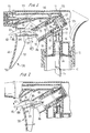
- Figure 1 is a side elevational view of a manually actuated dispensing pump incorporating the child resistant feature of the invention, partly broken away and sectioned, the trigger actuator being shown in its locked position;
- Figure 2 is a view similar to Figure 1 with the trigger lever shown in its unlocked position;
- Figure 3 is a view similar Figure 1 showing a reduced portion of the dispenser incorporating a latch according to another embodiment of the invention;
- Figure 4 is a sectional view taken substantially along the line 4-4 of Figure 3;
- Figure 5 is a view similar to Figure 1 showing a reduced section of the dispenser incorporating a latch according to another embodiment of the invention; and
- Figure 6 is a view similar to Figure 5 showing the trigger lever in its unlocked position.
- Turning now to the drawings wherein like reference characters refer to like and corresponding parts throughout the several views, the pump structure illustrated in the drawings is of the general type disclosed in U.S. Patent No. 4,747,523, commonly owned herewith. The child-resistant feature of the invention is disclosed for use with this prior patented pump, although the invention is likewise adaptable for use with any trigger actuated pump structure.
- The pump represented in the drawings comprises a pump housing or
body 10 which may have an outer shroud cover 11, the body being adapted for mounting with aclosure cap 12 at the neck of a container C not otherwise shown. An inner cylinder 13 of the pump body supports atube retainer 14 which suspends a conventional dip tube 15 extending into the interior of the container. The dip tube and upper end of the tube retainer define andinlet passage 16 which is valve controlled by a conventionalball check valve 17 supported on a valve seat at the upper end of the tube retainer. - A
pump cylinder 18 located above the closure cap opens at its outer end to the atmosphere and has at its inner end region apump chamber 19 for a manuallyreciprocable pump piston 21. Acoil return spring 22 extends between awall 23 of the pump chamber and some suitable portion of the piston for extending the-piston outwardly of the cylinder to its inoperative position of Figure 1. - The inlet passage terminates in an
inlet port 24 which opens into the pump chamber. Adischarge port 25 opening from the pump chamber communicates withdischarge passage 26 which is valve controlled by suitable valving located within arotable nozzle cap 27. - A
trigger lever actuator 28 is hinged at its upper end 29 to the pump body, the trigger having a rearwardly extendingtup 31 intermediate its upper end 29 and its opposing free end 30 the tup bearing against an outercircular rim 32 of the piston. - The pump cylinder also has a sump/vent port 33.
- The pump piston has an inboard
annular piston seal 34 in sealing engagement with the wall of the pump chamber. This piston seal extends in a direction toward the pump chamber and is spaced fromcylindrical wall 35 of the nose of the piston to form a convenient shoulder for the reception ofreturn spring 22. And, the piston has an outboardannular piston seal 36 which sealingly engages the wall ofcylinder 18 in the inoperative position shown in Figure 1. - To operate the pump, the trigger is simply pulled back using 2 or 3 finger of the operator's hand for shifting the piston inwardly, as shown in Figure 2, against the force of the return spring, and releasing the trigger to return to its Figure 1 postion.
- The trigger lever comprises a pair of
spaced sidewalls 37, 38 (Fig. 4), withtup 31 extending from each sidewall so as to bear againstpiston rim 32. Atransverse wall 39spans side walls piston 32 to avoid any slippage or disengagement of the tup from the piston rim. - The trigger lever has another
transverse wall 41 which spanssidewalls wall 39. And, the trigger has a slightly curvedfront wall 42 presenting a forward finger engaging surface of the trigger. - In accordance with the invention, latch means, generally designated 43 in Figures 1-3, is provided for
locking trigger lever 28 in the inoperative postion of the pump piston, shown in Figure 1. The latch means comprises a latch pivotally mounted on the trigger lever betweenopposing side walls transverse walls extension 45 which may have a blunt end, and of a predetermined length as to a butt against a confronting portion of the pump body, such asfree end 46 ofpump cylinder 18. - And, the latch has a forwardly extending arm or
projection 47 extending outwardly beyond thefront wall 42 of the trigger lever through asuitable slot 48 formed therein.Arm 47 has a predetermined length as to lifted by, for example, the upward surface of the operator's forefinger at the time the trigger lever is actuated, as will be described more fully hereinafter. - The latch further includes an
integral spring tab 49 which bears againsttransverse wall 39 as shown, while the upper flat surface ofextension 45 bears againsttransverse wall 41 in the Fig. 1 position.Spring tab 49, or some other equivalent resilient means such as a coil spring, a leaf spring, a resilient pad, or the like, is located beneathextension 45. - In operation, the operator simply grasps
trigger lever 28, usually with the forefinger and middle finger of one hand, while the trigger lever is in its forwardly extended position of Figure 1 withextension 45 in abutting engagement withfree end 46 of the pump cylinder which locks the trigger lever against trigger actuation. While the trigger lever is grasped in this condition, application of a slight upward force againstprojection 47, by simply shifting the forefinger of the operator in the direction of the arrow of Figure 2, pivots the latch at its pivot pin in a clockwise direction viewed in Figure 2, thereby causingextension 45 to pivot downwardly and out of engagement withfree end 46 against the bias ofspring tab 49, instantaneously prior to pulling back on the trigger lever which thereby permits the lever to be actuated for pumping. As shown in Figure 2,extention 45 simply moves slightly into the hollow open end ofpump cylinder 18, without interfering with either the pump cylinder or the pump piston. - Upon release of the trigger lever, the pump piston reciprocates outwardly in its pump cylinder under the action of the
return spring 22, for suctioning product from the container into the pump chamber as in the normal pumping operation. Continued pumping and suction strokes are faciliated upon repeated pulls of the trigger lever while the operator maintains the pivoted attitude of the latch as shown in Figure 2. At the end of a given pumping operation, the operator simply relaxes his grip on the trigger lever and releasesprojection 47 at whichtime spring tab 49 automatically pivots the latch back to its Figure 1 position at whichextension 45 again butts againstfree end 46. - Since upper
transverse wall 41 fully spansside walls projection 47 is shifted in the direction toward upper end 29 of the trigger. However, by providinglongitudinal slits wall 41 andside walls spring tab 41A. Thus, the latch may now be shifted in a counter-clockwise direction, when viewed in Figure 3, as theoperator depresses projection 47 with his forefinger as he grasps the trigger lever to thereby releaseextension 45 from its engagement withfree end 46, as shown in Figure 3. The trigger may then be pulled for pumping as aforedescribed without interference byextension 45 with either the pump cylinder or the pump piston. Depression ofprojection 47 in the direction of the arrow of Figure 3, pivots the latch against the bias ofspring tab 41A, so that upon release of the latch by the operator, the spring tab automatically returns the latch back to its locked position of Figure 1. Of course, the latch in the Figure 3 embodiment may likewise be pivoted in a clockwise direction by shiftingprojection 47 upwardly in the direction of the arrow Figure 2, as described with reference to Figures 1 and 2. The Figure 3 embodiment therefore permitsprojection 47 to be either pushed upwardly or pulled downwardly by the operator for unlocking the trigger lever. - In another embodiment shown in Figures 5 and 6, latch means, generally designated 53, is pivotally mounted on the trigger lever, similarly as described with reference to Figure 1, and is positioned between
transverse walls Extension 45 of the latch, in the Figure 5 position, butts againstfree end 46 for disenabling or locking the trigger against actuation. In this version,spring tab 49underlies projection 47 of the latch thereby permitting the latch to be pivoted counterclockwise when viewed in Figures 5 and 6, asprojection 47 is pulled downwardly by the operator in the direction of the arrow shown for unlocking the trigger just prior to trigger actuation. As shown in Figure 6,extension 45 is shifted out of engagement withfree end 46 of the pump cylinder thereby facilitating trigger actuation during pumping without interference with the pump cylinder or with the pump piston. Again, at the end of a given pumping operation, the operator simply releasesprojection 47 where uponspring tab 49 automatically returns the latch to its locked position of Figure 5. - From the foregoing, it can be seen that a simple and economical yet highly effective manually actuated latch is provided for locking the trigger lever against actuation to thereby render the pump dispenser fully child-resistant.
Projection 47 of the latch is either pushed upwardly, or downwardly, or both, depending on the arrangement described, by the same hand of the operator used in grasping the trigger lever such that little effort is required by the adult operator in maintaining the latch in its unlocked position during use, while at the same time providing for a similar operation incapable of being carried out by the child. And, eachtime projection 47 of the latch is released, at the end of each pumping operation, the spring tab, or other resilient means employed, automatically returns the latch to its locked position. - Obviously, many other modifications and variations of the present invention as defined by the appended claims are made possible in the light of the teachings. It is therefore to be understood that within the scope of these claims the invention may be practiced otherwise than as specifically described.
Claims (8)
- A child-resistant trigger operated pump dispenser comprising, a pump body (10) for mounting with a closure cap (12) at the upper end of a container for fluent product, a trigger lever actuator (28) pivotally mounted at an upper end (29) to said body, said actuator having an opposing free end (30) and rearwardly extending means (31) intermediate said ends for actuating said pump dispenser upon manual operation of said lever, said actuator having a forward finger engaging surface (42) extending between said ends, and latch means (43) for preventing trigger actuation characterised in that said latch means is supported on said lever for preventing trigger actuation in a first position of said latch means, said latch means having an extension (45) in abutting engagement with a confronting portion (46) of said pump body in said first position and being pivotally mounted on said lever, biasing means (49) acting on said latch means, said latch means having a projection (47) extending forwardly beyond said finger engaging surface for manually pivoting said latch against the bias of said biasing means from said first position to a second position in which said extension is out of engagement with said body to permit trigger actuation, said biasing means automatically returning said latch means to said first position upon release of the projection (47) at the end of the pumping operation.
- A dispenser according to claim 1, wherein said biasing means (49) is located at least beneath said extension (45) permitting pivotal movement of said latch means (43) as said projection (47) is moved toward one or either one of said ends.
- A dispenser according to claim 1, wherein said biasing means (49) is located beneath said projection (47) permitting pivotal movement of said latch means (43) as said projection is moved toward said free end (30).
- A dispenser according to claim 2, wherein said biasing means (49) is further located above said extension (45) permitting pivotal movement of said latch means (43) as said projection (47) is moved toward said free end (30).
- A dispenser according to any preceding claim, wherein said pump body (10) includes a pump cylinder (18) and a reciprocable piston (21) operable within said cylinder for defining together therewith a variable volume pump chamber (19), said latch means extension (45) abutting an edge (46) of said cylinder in said first position.
- A dispenser according to any preceding claim, wherein said biasing means (49) comprises a spring tab.
- A dispenser according to claim 6, wherein said spring tab is integral with said latch means (43).
- A dispenser according to claim 6, wherein said spring tab is integral with said lever (28).
Applications Claiming Priority (2)
| Application Number | Priority Date | Filing Date | Title |
|---|---|---|---|
| US07/606,455 US5114049A (en) | 1990-10-31 | 1990-10-31 | Child-resistant trigger sprayer |
| US606455 | 1990-10-31 |
Publications (2)
| Publication Number | Publication Date |
|---|---|
| EP0484002A1 EP0484002A1 (en) | 1992-05-06 |
| EP0484002B1 true EP0484002B1 (en) | 1994-05-04 |
Family
ID=24428056
Family Applications (1)
| Application Number | Title | Priority Date | Filing Date |
|---|---|---|---|
| EP91309488A Expired - Lifetime EP0484002B1 (en) | 1990-10-31 | 1991-10-15 | Child-resistant trigger sprayer |
Country Status (9)
| Country | Link |
|---|---|
| US (1) | US5114049A (en) |
| EP (1) | EP0484002B1 (en) |
| JP (1) | JPH0824861B2 (en) |
| AU (1) | AU634408B2 (en) |
| CA (1) | CA2045372C (en) |
| DE (1) | DE69101898T2 (en) |
| ES (1) | ES2056585T3 (en) |
| HK (1) | HK156996A (en) |
| MX (1) | MX173459B (en) |
Cited By (1)
| Publication number | Priority date | Publication date | Assignee | Title |
|---|---|---|---|---|
| EP0838266A1 (en) * | 1996-10-24 | 1998-04-29 | Calmar-Albert GmbH | Child-resistant latch for trigger sprayer |
Families Citing this family (30)
| Publication number | Priority date | Publication date | Assignee | Title |
|---|---|---|---|---|
| US5228602A (en) * | 1992-02-24 | 1993-07-20 | Afa Products Inc. | Plastic spring assembly for trigger sprayer |
| TW253844B (en) * | 1992-02-24 | 1995-08-11 | Afa Products Inc | |
| US5402916A (en) * | 1993-06-22 | 1995-04-04 | Nottingham Spirk Design Associates | Dual chamber sprayer with metering assembly |
| US5649646A (en) | 1995-06-02 | 1997-07-22 | Contico International, Inc. | Child resistant nozzle |
| US5755384A (en) * | 1995-08-01 | 1998-05-26 | Contico International, Inc. | Dispenser with selectable discharge nozzle |
| US5706983B1 (en) * | 1995-08-18 | 1999-08-24 | Calmar Inc | Trigger sprayer having a nozzle cover |
| JPH09291879A (en) * | 1996-04-26 | 1997-11-11 | Canyon Corp | Pump dispenser |
| ID18608A (en) * | 1996-10-22 | 1998-04-23 | Yoshino Kogyosho Co Ltd | TYPE-PICU FLUID DISPENSER |
| US5823395A (en) * | 1997-04-24 | 1998-10-20 | Continental Sprayers International, Inc. | Child-resistant pump dispenser |
| US6003738A (en) * | 1997-12-29 | 1999-12-21 | Continental Sprayers International,Inc. | Child-resistant rotating lock for manually operated pump dispenser |
| FR2773115B1 (en) | 1997-12-30 | 2000-03-24 | Francois Mundler | SYSTEM AND METHOD FOR COOLING THE INTERIOR AIR OF THE INTERIOR OF A MOTOR VEHICLE |
| US6244469B1 (en) | 1998-01-14 | 2001-06-12 | Michael G. Knickerbocker | Child resistant trigger for dispenser |
| US6095377A (en) | 1999-03-26 | 2000-08-01 | Calmar Inc. | Liquid dispensing pump |
| US6286723B1 (en) | 2000-03-06 | 2001-09-11 | Saint-Gobain Calmar Inc. | Self-resetting child-resistant trigger sprayer |
| US6626945B2 (en) * | 2000-03-14 | 2003-09-30 | Chondrosite, Llc | Cartilage repair plug |
| US20020033424A1 (en) * | 2000-08-02 | 2002-03-21 | Santagio Rivera | Shower apparatus |
| US6431468B1 (en) | 2000-11-06 | 2002-08-13 | Flexible Products Company | Safety mechanism for dispensing apparatus |
| JP3904918B2 (en) * | 2001-12-26 | 2007-04-11 | 株式会社吉野工業所 | Trigger type liquid ejector |
| US7032777B2 (en) * | 2003-10-16 | 2006-04-25 | Saint-Gobain Calmar, Inc. | Child-resistant trigger sprayer |
| JP2005219003A (en) * | 2004-02-06 | 2005-08-18 | Canyon Corp | Pump dispenser with trigger |
| US20090057339A1 (en) * | 2007-08-28 | 2009-03-05 | Piscotty Elizabeth N | Child-Resistant Closure for Bag-in-Box Dispenser |
| HK1123157A2 (en) * | 2008-04-10 | 2009-06-05 | Alex Brands Buzz Bee Toys (Hk) Limited | Toy water shooter |
| US20100320237A1 (en) * | 2009-06-17 | 2010-12-23 | Accredit Innovations Limited | Fluid dispensing apparatus with lockable actuator |
| US8757447B2 (en) | 2011-11-02 | 2014-06-24 | Nationwide Children's Hospital, Inc. | Spray device |
| FR3010746B1 (en) * | 2013-09-18 | 2015-09-25 | Rowenta Werke Gmbh | MANUAL PUMP FOR AN APPARATUS FOR ELECTRICALLY INCLUDING A DEVICE FOR IRONING |
| WO2017025138A1 (en) * | 2015-08-11 | 2017-02-16 | Edker B.V. | Automatic trigger-lock safety mechanism, device comprising an automatic triggerlock safety mechanism and method for automatically locking a device such as an airless spray gun or a high pressure spray gun |
| CN105546339B (en) * | 2016-02-04 | 2018-10-19 | 温岭正峰动力有限公司 | A kind of automobile freon air interchanger |
| WO2022127832A1 (en) * | 2020-12-15 | 2022-06-23 | 北京红海科技开发有限公司 | Pump head element and pump head comprising same, and container |
| WO2022127836A1 (en) * | 2020-12-15 | 2022-06-23 | 北京红海科技开发有限公司 | Pump head and container |
| JP7576995B2 (en) * | 2021-02-26 | 2024-11-01 | 株式会社吉野工業所 | Trigger-type liquid ejector |
Family Cites Families (8)
| Publication number | Priority date | Publication date | Assignee | Title |
|---|---|---|---|---|
| US3828982A (en) * | 1973-05-10 | 1974-08-13 | Vca Corp | Safety actuator for aerosol containers |
| US3940023A (en) * | 1974-11-27 | 1976-02-24 | Avon Products, Inc. | Child-proof safety locking device |
| US4516695A (en) * | 1981-02-09 | 1985-05-14 | The Afa Corporation | Child-resistant liquid dispenser sprayer or like apparatus |
| US4805812A (en) * | 1987-12-11 | 1989-02-21 | Delshar Industries, Inc. | Spray can actuation device with locking mechanism |
| US4982900B1 (en) * | 1988-05-16 | 1998-05-05 | William S Blake | Trigger sprayer |
| US4880143A (en) * | 1988-10-20 | 1989-11-14 | Insta-Foam Products | Dispenser and components for high viscosity foam products |
| US4946074A (en) * | 1989-06-15 | 1990-08-07 | Calmar, Inc. | Tamper evident manually actuated pump sprayer |
| JP5432961B2 (en) | 2011-08-25 | 2014-03-05 | 株式会社ソフイア | Game machine |
-
1990
- 1990-10-31 US US07/606,455 patent/US5114049A/en not_active Expired - Fee Related
-
1991
- 1991-06-25 CA CA002045372A patent/CA2045372C/en not_active Expired - Fee Related
- 1991-07-25 JP JP3208663A patent/JPH0824861B2/en not_active Expired - Lifetime
- 1991-07-29 AU AU81410/91A patent/AU634408B2/en not_active Ceased
- 1991-08-15 MX MX9100673A patent/MX173459B/en not_active IP Right Cessation
- 1991-10-15 ES ES91309488T patent/ES2056585T3/en not_active Expired - Lifetime
- 1991-10-15 DE DE69101898T patent/DE69101898T2/en not_active Expired - Fee Related
- 1991-10-15 EP EP91309488A patent/EP0484002B1/en not_active Expired - Lifetime
-
1996
- 1996-08-15 HK HK156996A patent/HK156996A/en not_active IP Right Cessation
Cited By (1)
| Publication number | Priority date | Publication date | Assignee | Title |
|---|---|---|---|---|
| EP0838266A1 (en) * | 1996-10-24 | 1998-04-29 | Calmar-Albert GmbH | Child-resistant latch for trigger sprayer |
Also Published As
| Publication number | Publication date |
|---|---|
| DE69101898D1 (en) | 1994-06-09 |
| EP0484002A1 (en) | 1992-05-06 |
| JPH0824861B2 (en) | 1996-03-13 |
| AU8141091A (en) | 1992-05-07 |
| MX173459B (en) | 1994-03-04 |
| ES2056585T3 (en) | 1994-10-01 |
| CA2045372C (en) | 1999-11-16 |
| CA2045372A1 (en) | 1992-05-01 |
| AU634408B2 (en) | 1993-02-18 |
| HK156996A (en) | 1996-08-23 |
| JPH04284873A (en) | 1992-10-09 |
| US5114049A (en) | 1992-05-19 |
| DE69101898T2 (en) | 1994-11-24 |
Similar Documents
| Publication | Publication Date | Title |
|---|---|---|
| US5114049A (en) | Child-resistant trigger sprayer | |
| US5297701A (en) | All plastic trigger sprayer | |
| JP3885884B2 (en) | Liquid dispenser for infant protection | |
| US3422996A (en) | Safety actuator cap for hand-held dispensers | |
| EP1524039B1 (en) | Child-resistant trigger spray | |
| US5823396A (en) | Child-resistant latch for trigger sprayer | |
| EP0528665B1 (en) | Protector cap and wiper for dispenser discharge orifice | |
| US4971227A (en) | Manually actuated dispensing pump sprayer having a removable nozzle locking element | |
| EP1407826A2 (en) | Actuation device for manually operated pump sprayer | |
| US5687880A (en) | Child lock nozzle cap assembly | |
| EP0641723B1 (en) | A manually operated trigger type dispenser | |
| JP2001314786A (en) | Automatic return type child accidental ingestion prevention trigger operation spray | |
| MXPA97004790A (en) | Children's proof insurance for asper trigger | |
| US6244469B1 (en) | Child resistant trigger for dispenser | |
| EP1277518B1 (en) | Child-resistant nozzle assembly for fluid dispenser | |
| US5848733A (en) | Manually operated pump dispenser having child-resistant nozzle | |
| US5040701A (en) | Manually actuated dispensing pump sprayer having a removable nozzle locking element | |
| US5657907A (en) | Orifice cover slide for trigger sprayer | |
| EP0861692A2 (en) | Trigger actuated pump sprayer | |
| US3501066A (en) | Attachable spray can actuation mechanism | |
| US20240124214A1 (en) | Dispensing systems, dispensers, and methods of use | |
| EP0872283B1 (en) | Child-resistant trigger actuated pump sprayer | |
| AU666361B2 (en) | Plastic spring assembly | |
| US20050133525A1 (en) | Lockout device for viscous liquid dispenser | |
| WO1998058872A1 (en) | Child-resistant nozzle for manual pump dispenser |
Legal Events
| Date | Code | Title | Description |
|---|---|---|---|
| PUAI | Public reference made under article 153(3) epc to a published international application that has entered the european phase |
Free format text: ORIGINAL CODE: 0009012 |
|
| AK | Designated contracting states |
Kind code of ref document: A1 Designated state(s): BE DE ES FR GB IT NL SE |
|
| 17P | Request for examination filed |
Effective date: 19921029 |
|
| 17Q | First examination report despatched |
Effective date: 19930212 |
|
| GRAA | (expected) grant |
Free format text: ORIGINAL CODE: 0009210 |
|
| AK | Designated contracting states |
Kind code of ref document: B1 Designated state(s): BE DE ES FR GB IT NL SE |
|
| PG25 | Lapsed in a contracting state [announced via postgrant information from national office to epo] |
Ref country code: SE Free format text: THE PATENT HAS BEEN ANNULLED BY A DECISION OF A NATIONAL AUTHORITY Effective date: 19940504 Ref country code: NL Effective date: 19940504 Ref country code: BE Effective date: 19940504 |
|
| RIN1 | Information on inventor provided before grant (corrected) |
Inventor name: KNICKERBOCKER, MICHAEL GENE |
|
| ITF | It: translation for a ep patent filed | ||
| REF | Corresponds to: |
Ref document number: 69101898 Country of ref document: DE Date of ref document: 19940609 |
|
| ET | Fr: translation filed | ||
| REG | Reference to a national code |
Ref country code: ES Ref legal event code: FG2A Ref document number: 2056585 Country of ref document: ES Kind code of ref document: T3 |
|
| NLV1 | Nl: lapsed or annulled due to failure to fulfill the requirements of art. 29p and 29m of the patents act | ||
| PLBE | No opposition filed within time limit |
Free format text: ORIGINAL CODE: 0009261 |
|
| STAA | Information on the status of an ep patent application or granted ep patent |
Free format text: STATUS: NO OPPOSITION FILED WITHIN TIME LIMIT |
|
| 26N | No opposition filed | ||
| PGFP | Annual fee paid to national office [announced via postgrant information from national office to epo] |
Ref country code: FR Payment date: 19991011 Year of fee payment: 9 |
|
| PGFP | Annual fee paid to national office [announced via postgrant information from national office to epo] |
Ref country code: GB Payment date: 19991013 Year of fee payment: 9 |
|
| PGFP | Annual fee paid to national office [announced via postgrant information from national office to epo] |
Ref country code: DE Payment date: 19991018 Year of fee payment: 9 |
|
| PGFP | Annual fee paid to national office [announced via postgrant information from national office to epo] |
Ref country code: ES Payment date: 19991020 Year of fee payment: 9 |
|
| PG25 | Lapsed in a contracting state [announced via postgrant information from national office to epo] |
Ref country code: GB Free format text: LAPSE BECAUSE OF NON-PAYMENT OF DUE FEES Effective date: 20001015 |
|
| PG25 | Lapsed in a contracting state [announced via postgrant information from national office to epo] |
Ref country code: ES Free format text: LAPSE BECAUSE OF NON-PAYMENT OF DUE FEES Effective date: 20001016 |
|
| GBPC | Gb: european patent ceased through non-payment of renewal fee |
Effective date: 20001015 |
|
| PG25 | Lapsed in a contracting state [announced via postgrant information from national office to epo] |
Ref country code: FR Free format text: LAPSE BECAUSE OF NON-PAYMENT OF DUE FEES Effective date: 20010629 |
|
| PG25 | Lapsed in a contracting state [announced via postgrant information from national office to epo] |
Ref country code: DE Free format text: LAPSE BECAUSE OF NON-PAYMENT OF DUE FEES Effective date: 20010703 |
|
| REG | Reference to a national code |
Ref country code: FR Ref legal event code: ST |
|
| REG | Reference to a national code |
Ref country code: ES Ref legal event code: FD2A Effective date: 20011113 |
|
| PG25 | Lapsed in a contracting state [announced via postgrant information from national office to epo] |
Ref country code: IT Free format text: LAPSE BECAUSE OF NON-PAYMENT OF DUE FEES Effective date: 20051015 |