EP0483912A1 - Disk-shaped shear force sensor for a load cell - Google Patents
Disk-shaped shear force sensor for a load cell Download PDFInfo
- Publication number
- EP0483912A1 EP0483912A1 EP91202742A EP91202742A EP0483912A1 EP 0483912 A1 EP0483912 A1 EP 0483912A1 EP 91202742 A EP91202742 A EP 91202742A EP 91202742 A EP91202742 A EP 91202742A EP 0483912 A1 EP0483912 A1 EP 0483912A1
- Authority
- EP
- European Patent Office
- Prior art keywords
- transducer
- section
- force
- center line
- openings
- Prior art date
- Legal status (The legal status is an assumption and is not a legal conclusion. Google has not performed a legal analysis and makes no representation as to the accuracy of the status listed.)
- Granted
Links
Images

Classifications
-
- G—PHYSICS
- G01—MEASURING; TESTING
- G01G—WEIGHING
- G01G3/00—Weighing apparatus characterised by the use of elastically-deformable members, e.g. spring balances
- G01G3/12—Weighing apparatus characterised by the use of elastically-deformable members, e.g. spring balances wherein the weighing element is in the form of a solid body stressed by pressure or tension during weighing
- G01G3/14—Weighing apparatus characterised by the use of elastically-deformable members, e.g. spring balances wherein the weighing element is in the form of a solid body stressed by pressure or tension during weighing measuring variations of electrical resistance
- G01G3/1402—Special supports with preselected places to mount the resistance strain gauges; Mounting of supports
- G01G3/141—Special supports with preselected places to mount the resistance strain gauges; Mounting of supports the supports being disc or ring shaped
-
- G—PHYSICS
- G01—MEASURING; TESTING
- G01G—WEIGHING
- G01G3/00—Weighing apparatus characterised by the use of elastically-deformable members, e.g. spring balances
- G01G3/12—Weighing apparatus characterised by the use of elastically-deformable members, e.g. spring balances wherein the weighing element is in the form of a solid body stressed by pressure or tension during weighing
- G01G3/14—Weighing apparatus characterised by the use of elastically-deformable members, e.g. spring balances wherein the weighing element is in the form of a solid body stressed by pressure or tension during weighing measuring variations of electrical resistance
- G01G3/1414—Arrangements for correcting or for compensating for unwanted effects
Definitions
- the invention relates to a disk-shaped sensor for a load cell, with surfaces arranged parallel to one another and parallel to the direction of action of a force to be measured, at least one of which has a sensor for converting a deformation dependent on the measuring force into an evaluable signal.
- Transducers of this type are usually part of a load cell for a load cell, which works according to the shear stress principle and has sensors.
- Such force transducers are, for example, from the brochure "Compression Load Cells, 1986” from Revere Corp. of Europe GmbH, 6382 Friedrichsdorf 2, DE.
- the type SSB force transducer from this brochure has a deformation body with a through opening that is oriented orthogonally to the line of action of the force to be measured and receives a transducer approximately in the middle.
- the transducer thus forms an intermediate wall that separates two symmetrical chambers.
- Strain gauges are arranged approximately in the middle on the surfaces of the disk-shaped transducers. In order to electrically connect the strain gauges to each other, through openings are provided on a center line of the transducer, which is parallel to the line of action of the force to be measured. These through openings also serve to adjust the rigidity of the sensor.
- the working accuracy of such a force transducer depends on the linearity and especially on the hysteresis of the measuring transducer.
- the linearity becomes practical determined solely by the geometric conditions.
- the hysteresis that is, the fact that the output signal of a deformed body depends on the previous course, in particular on the amount and the direction of change of a deformation quantity, is a material property and consequently on the material. Since the material-related hysteresis cannot completely disappear even when using specially selected materials, this is a major disadvantage of known force transducers, since this limits the accuracy, which is disadvantageous particularly with regard to their use subject to verification.
- the present invention has for its object to provide a transducer for a load cell that provides a quasi hysteresis-free, calibratable and evaluable signal when it is scanned by at least one sensor.
- the transducer has four sub-areas formed by a center line parallel to the direction of action of the force and a center line orthogonal thereto, of which at least two sub-areas lying only at one point each have an area with a reduced cross-section for influencing the Exhibit hysteresis effect.
- transducers according to the invention are particularly insensitive to overload, so that transducers are available which can be used well in the area subject to calibration.
- the partial surfaces of the transducer lying in the greatest force flow each have an area with a reduced cross section.
- all four partial areas have an area with a reduced cross section.
- the senor can be circular, that is, it can end in the direction of the orthogonal center line, each with a semicircular section.
- Through openings with a circular cross section can advantageously form the regions with a reduced cross section in the partial surfaces.
- the center of these through openings lies advantageously on a radius that forms an angle of 45 o ⁇ 15 o with one of the center lines.
- the diameter of the through openings in the partial areas advantageously corresponds to 10 to 30% of the diameter of the circular transducer or the semicircular sections.
- the transducer has through-openings on both sides of the center of the sections on the center line lying parallel to the direction of action of the force in the edge region of the transducer.
- these through openings have only a slight influence on the hysteresis to be compensated, they offer the possibility of accommodating connecting elements, such as lines for the sensors, for example designed as strain gauges, which can be arranged on both surfaces of the sensor.
- these through openings serve to adjust the stiffness or the sensitivity of the sensor and for this purpose advantageously have a maximum diameter of 40% of the diameter of the circular sensor or the semicircular sections.
- the senor has a rectangular section between the two semicircular sections, which correspond to the two halves of a circular sensor.
- the centers of the through holes in the corresponding part surfaces are arranged in this embodiment of the invention in a range which is bounded by the orthogonal center line, the 45 ° total angle, an adjacent circular arc portion of a semi-circular portion and an adjacent diagonal of the rectangular portion.
- the senor is constructed from a measuring bridge circuit and is applied as a strain gauge or by thin film technology to the surface of the sensor, which in turn can be made of high quality material.
- a transducer according to the invention can moreover be used in virtually all shear force transducers that occur practically and can also be formed in one piece with it.
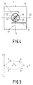
- Fig. 1 shows a disc-shaped transducer 10 according to the invention, which is arranged standing on its edge in a through opening 11 of a force transducer 12.
- the force transducer 12 shown is loaded with a force F as a shear force transducer.
- the transducer 10 is in the through opening 11 of the force transducer 12 welded, glued, pressed or the like. and has a sensor 13 approximately centrally on each of its mutually parallel surfaces 14.
- the transducer 10 and the force transducer 12 can also be formed in one piece.
- the sensors 13 are constructed as a measuring bridge circuit and applied as strain gauges or by thin film technology to the surfaces 14 of the sensor 10. They are used to convert the deformations dependent on the measuring force that are transmitted from the deformation body, ie the force transducer 12 to the measurement transducer 10, into a preferably electrical, evaluable signal.
- the through openings 15 are preferably arranged in the edge region of the sensor 14. As a result, they also serve to adjust the rigidity or sensitivity of the sensor 14.
- the through openings 15 preferably have a diameter 18 of at most 40% of the diameter 19 (see FIG. 2) of the preferably circular sensor 10.
- the transducer 10 is divided into four partial areas 21 by the center line 17 and a center line 20 running orthogonally thereto. At least two of these partial areas 21, which only touch at the center 16 or are only closest at one point, have an area with a reduced cross section or thickness. It should be noted here that the transducer 10 has a constant cross section 22 or a constant thickness (see FIG. 2).
- the areas with a reduced cross section of the transducer 10 are preferably formed by through openings 23 with a circular cross section.
- the center point of the through openings 23 preferably lies on a radius 24 which has an angle 25 of 45 ° ⁇ 15 ° with one of the center lines 17 or 20 and the center point 16. This area is indicated by hatching in FIGS. 1 and 4.
- the through openings 23 in the partial surfaces 21 preferably have a diameter 26 of 10 to 30% of the diameter 19 of the circular transducer 10 or the semicircular sections 27.
- FIG. 2 shows a section of FIG. 1 along the line BB.
- the cross section of the force transducer 12 which has a through opening 11 in its central section, in which the measurement transducer 10 is arranged and fastened, can be clearly seen.
- the cross section 22 or the thickness of the transducer 10 is constant per se.
- a measuring sensor 13 is arranged in the middle on the surfaces 14 of the measuring transducer 10 in the middle region. In order to ensure a connection for connecting lines (not shown) of the measuring sensors 13 on one and the other surface 14 of the measuring sensor 10, 13 through openings 15 are shown above and below the measuring sensors intended. These also serve to adjust the rigidity or the sensitivity of the transducer 10.
- the shape of a force transducer 12 selected in FIGS. 1 to 3 is only an example and the transducer 10 according to the invention also in another force transducer 12 can be used with a different shape, as shown for example in Fig. 4.
- a force transducer 12 is shown, which largely corresponds to that shown in Figs. 1 and 2, but has a transducer 10 which ends in the direction of the orthogonal center line 20 with semicircular sections 27 and a rectangular section 28 is arranged between them.
- a force transducer 12 is particularly favorable in terms of rigidity or sensitivity and can also be provided with through openings 23 according to the invention in the correspondingly supplemented partial areas 21.
- the center points of the through openings 23 are preferably arranged in the partial areas 21 in the area 30 hatched in FIG. 3.
- the rectangular section 28 has a length 29.
- An optimal position of the through openings 23 in the permissible range 30 results as a function of the measuring grids of the sensors 13, that is to say from their internal structure.
- the view according to FIG. 2 corresponds to the section CC of FIG. 3.
- FIG. 4 shows a further variant of a force transducer 12 which, as shown, can have square but also circular dimensions and contains a measurement transducer 10 according to the invention.
- This is an S-shaped force transducer 12, which is particularly well suited for compressive and tensile forces, and through its slot-like recesses 31 converts it into a shear force load, which is then transferred to a centrally arranged transducer 10, roughly corresponding to that shown in Fig. 1 shown transducer 10 acts.
- the senor 13 can be constructed from a measuring bridge circuit and can be applied as a strain gauge or by thin film technology to the surface 14 of the sensor 10, which in turn is made of high quality material.
- Fig. 5 shows a right-angled coordinate system, on the ordinate the hysteresis error and on the abscissa the force F is plotted.
- the hysteresis error is related to the final value of the force F.
- the arrows D indicate a normal course of the hysteresis error, ie the hysteresis when a measuring sensor is loaded, which is not according to the invention.
- the arrows E indicate the course of the hysteresis errors in a sensor 10 designed according to the invention. It can be clearly seen that the course of the hysteresis error in the transducer 10 according to the invention can be completely reversed.
- the through openings 15 can also always be provided, so that a low-hysteresis or hysteresis-free force transducer according to the invention can also have six through openings according to FIG. 1.
Landscapes
- Physics & Mathematics (AREA)
- General Physics & Mathematics (AREA)
- Measurement Of Force In General (AREA)
- Force Measurement Appropriate To Specific Purposes (AREA)
Abstract
Description
Die Erfindung betrifft einen scheibenförmigen Meßwertaufnehmer für eine Wägezelle, mit parallel zueinander und parallel zur Wirkrichtung einer zu messenden Kraft angeordneten Oberflächen, von denen mindestens eine einen Meßfühler zur Umwandlung einer meßkraftabhängigen Verformung in ein auswertbares Signal aufweist.The invention relates to a disk-shaped sensor for a load cell, with surfaces arranged parallel to one another and parallel to the direction of action of a force to be measured, at least one of which has a sensor for converting a deformation dependent on the measuring force into an evaluable signal.
Meßwertaufnehmer dieser Art sind in der Regel Bestandteil eines Kraftaufnehmers für eine Wägezelle, der nach dem Scherspannungsprinzip arbeitet und Meßfühler besitzt.Transducers of this type are usually part of a load cell for a load cell, which works according to the shear stress principle and has sensors.
Derartige Kraftaufnehmer sind beispielsweise aus der Broschüre "Compression Load Cells, 1986" der Firma Revere Corp. of Europe GmbH, 6382 Friedrichsdorf 2, DE, bekannt. Der Kraftaufnehmer Typ SSB aus dieser Broschüre weist einen Verformungskörper mit einer Durchgangsöffnung auf, die orthogonal zur Wirklinie der zu messenden Kraft ausgerichtet ist und einen Meßwertaufnehmer etwa mittig aufnimmt. Der Meßwertaufnehmer bildet somit eine Zwischenwand, die zwei symmetrische Kammern trennt. Auf den Oberflächen des scheibenförmigen Meßwertaufnehmers sind etwa mittig Dehnungsmeßstreifen als Meßfühler angeordnet. Um die Dehnungsmeßstreifen elektrisch miteinander zu verbinden, sind Durchgangsöffnungen auf einer Mittellinie des Meßwertaufnehmers vorgesehen, die parallel zur Wirklinie der zu messenden Kraft liegt. Diese Durchgangsöffnungen dienen ebenfalls dazu, die Steifigkeit des Meßwertaufnehmers einzustellen.Such force transducers are, for example, from the brochure "Compression Load Cells, 1986" from Revere Corp. of Europe GmbH, 6382 Friedrichsdorf 2, DE. The type SSB force transducer from this brochure has a deformation body with a through opening that is oriented orthogonally to the line of action of the force to be measured and receives a transducer approximately in the middle. The transducer thus forms an intermediate wall that separates two symmetrical chambers. Strain gauges are arranged approximately in the middle on the surfaces of the disk-shaped transducers. In order to electrically connect the strain gauges to each other, through openings are provided on a center line of the transducer, which is parallel to the line of action of the force to be measured. These through openings also serve to adjust the rigidity of the sensor.
Die Arbeitsgenauigkeit eines solchen Kraftaufnehmers ist von der Linearität und besonders von der Hysterese des Meßwertaufnehmers abhängig. Die Linearität wird praktisch allein durch die geometrischen Verhältnisse bestimmt. Dagegen ist die Hysterese, also die Tatsache, daß das Ausgangssignal eines verformten Körpers vom vorhergehenden Verlauf, insbesondere vom Betrag und der Änderungsrichtung einer Verformungsgröße abhängig ist, eine Werkstoffeigenschaft und folglich vom Werkstoff abhängig. Da der werkstoffbedingte Hystereseanteil auch bei Verwendung besonders ausgewählter Werkstoffe nicht völlig verschwinden kann, ist dies ein wesentlicher Nachteil von bekannten Kraftaufnehmern, da dadurch die Genauigkeit begrenzt wird, was besonders im Hinblick auf ihre eichpflichtige Verwendung nachteilig ist.The working accuracy of such a force transducer depends on the linearity and especially on the hysteresis of the measuring transducer. The linearity becomes practical determined solely by the geometric conditions. In contrast, the hysteresis, that is, the fact that the output signal of a deformed body depends on the previous course, in particular on the amount and the direction of change of a deformation quantity, is a material property and consequently on the material. Since the material-related hysteresis cannot completely disappear even when using specially selected materials, this is a major disadvantage of known force transducers, since this limits the accuracy, which is disadvantageous particularly with regard to their use subject to verification.
Ein weiterer Nachteil der bekannten Kraftaufnehmer liegt darin, daß deren gewünschte Genauigkeit bei einer Überlastung verlorengeht.Another disadvantage of the known force transducers is that their desired accuracy is lost in the event of an overload.
Der vorliegenden Erfindung liegt die Aufgabe zugrunde, einen Meßwertaufnehmer für eine Wägezelle zu schaffen, der ein quasi hysteresefreies, eichfähiges und auswertbares Signal liefert, wenn er über mindestens einen Meßfühler abgetastet wird.The present invention has for its object to provide a transducer for a load cell that provides a quasi hysteresis-free, calibratable and evaluable signal when it is scanned by at least one sensor.
Diese Aufgabe wird erfindungsgemäß dadurch gelöst, daß der Meßwertaufnehmer vier durch eine Mittellinie parallel zur Wirkrichtung der Kraft und einer hierzu orthogonalen Mittellinie gebildete Teilflächen aufweist, von denen mindestens zwei sich nur in einem Punkt am nächsten liegende Teilflächen je einen Bereich mit verringertem Querschnitt zur Beeinflussung des Hystereseeffekts aufweisen.This object is achieved in that the transducer has four sub-areas formed by a center line parallel to the direction of action of the force and a center line orthogonal thereto, of which at least two sub-areas lying only at one point each have an area with a reduced cross-section for influencing the Exhibit hysteresis effect.
Überraschenderweise hat sich bei Versuchen gezeigt, daß eine erfindungsgemäße Ausbildung des Meßwertaufnehmers mit Bereichen mit verringertem Querschnitt bzw. verringerter Dicke geeignet ist, durch eine Umlenkung und/oder Konzentration des Kraftflusses im Meßaufnehmer, eine Reduzierung der materialabhängigen Hysterese zu erzeugen. Bei Überlastungsversuchen hat sich ferner gezeigt, daß erfindungsgemäße Meßwertaufnehmer besonders unempfindlich sind gegen Überlastung, so daß Meßwertaufnehmer zur Verfügung stehen, die im eichpflichtigen Bereich gut eingesetzt werden können.Surprisingly, tests have shown that an inventive design of the transducer with areas with a reduced cross section or reduced Thickness is suitable for reducing the material-dependent hysteresis by deflecting and / or concentrating the force flow in the sensor. In overload tests, it has also been shown that transducers according to the invention are particularly insensitive to overload, so that transducers are available which can be used well in the area subject to calibration.
Bei einer besonderen Ausgestaltung der Erfindung ist vorgehsen, daß die im größten Kraftfluß liegenden Teilflächen des Meßwertaufnehmers je einen Bereich mit verringertem Querschnitt aufweisen. Den Kompensationseffekt der Hysterese verstärkend, kann auch vorgesehen sein, daß alle vier Teilflächen einen Bereich mit verringertem Querschnitt aufweisen. Bei solchen erfindungsgemäßen Meßwertaufnehmern hat sich gezeigt, daß nicht nur jeder beliebige materialabhängige Hystereseeffekt kompensiert werden kann, sondern sogar ein Verhalten des Meßfühlers möglich ist, daß dem Vorhandensein einer negativen Hysterese gleichkommt.In a special embodiment of the invention it is provided that the partial surfaces of the transducer lying in the greatest force flow each have an area with a reduced cross section. To increase the compensation effect of the hysteresis, it can also be provided that all four partial areas have an area with a reduced cross section. With such transducers according to the invention, it has been shown that not only can any material-dependent hysteresis effect be compensated for, but that the sensor can even behave in such a way that a negative hysteresis is present.
Die Verkleinerung der Hysterese hat zur Folge, daß dadurch Meßwertaufnehmer mit sehr kleinen Abweichungen vom streng linearen Verhalten realisierbar sind, was besonders für eichfähige Aufnehmer von Vorteil ist.The reduction in the hysteresis has the consequence that sensors with very small deviations from the strictly linear behavior can be realized, which is particularly advantageous for verifiable sensors.
Gemäß einer bevorzugten Ausgestaltung der Erfindung kann der Meßwertaufnehmer kreisrund ausgebildet sein, also in Richtung der orthogonalen Mittellinie mit je einem halbkreisförmigen Abschnitt enden.According to a preferred embodiment of the invention, the sensor can be circular, that is, it can end in the direction of the orthogonal center line, each with a semicircular section.
Vorteilhaft können Durchgangsöffnungen mit kreisförmigem Querschnitt die Bereiche mit verringertem Querschnitt in den Teilflächen bilden. Der Mittelpunkt dieser Durchgangsöffnungen liegt vorteilhaft auf einem Radius, der mit einer der Mittellinien einen Winkel von 45o ± 15o bildet. Der Durchmesser der Durchgangsöffnungen in den Teilflächen entspricht vorteilhaft 10 bis 30 % des Durchmessers des kreisrunden Meßwertaufnehmers, bzw. der halbkreisförmigen Abschnitte.Through openings with a circular cross section can advantageously form the regions with a reduced cross section in the partial surfaces. The center of these through openings lies advantageously on a radius that forms an angle of 45 o ± 15 o with one of the center lines. The diameter of the through openings in the partial areas advantageously corresponds to 10 to 30% of the diameter of the circular transducer or the semicircular sections.
Gemäß einer vorteilhaften Ausgestaltung der Erfindung kann vorgesehen sein, daß der Meßwertaufnehmer Durchgangsöffnungen auf beiden Seiten des Mittelpunktes der Abschnitte auf der parallel zu der Wirkrichtung der Kraft liegenden Mittellinie im Randbereich des Meßwertaufnehmers aufweist. Diese Durchgangsöffnungen haben zwar nur einen geringen Einfluß auf die zu kompensierende Hysterese, bieten jedoch die Möglichkeit zur Aufnahme von Verbindungselementen, wie Leitungen für die beispielsweise als Dehnungsmeßstreifen ausgebildeten Meßfühler, die auf beiden Oberflächen des Meßwertaufnehmers angeordnet sein können. Ferner dienen diese Durchgangsöffnungen der Anpassung der Steifheit, bzw. der Empfindlichkeit des Meßwertaufnehmers und haben hierzu vorteilhaft einen maximalen Durchmesser von 40 % des Durchmessers des kreisförmigen Meßwertaufnehmers, bzw. der halbkreisförmigen Abschnitte.According to an advantageous embodiment of the invention, it can be provided that the transducer has through-openings on both sides of the center of the sections on the center line lying parallel to the direction of action of the force in the edge region of the transducer. Although these through openings have only a slight influence on the hysteresis to be compensated, they offer the possibility of accommodating connecting elements, such as lines for the sensors, for example designed as strain gauges, which can be arranged on both surfaces of the sensor. Furthermore, these through openings serve to adjust the stiffness or the sensitivity of the sensor and for this purpose advantageously have a maximum diameter of 40% of the diameter of the circular sensor or the semicircular sections.
Gemäß einer vorteilhaften Ausgestaltung der Erfindung hat der Meßwertaufnehmer einen rechteckigen Abschnitt zwischen den zwei halbkreisförmigen Abschnitten, die den beiden Hälften eines kreisförmigen Meßwertaufnehmer entsprechen. Die Mittelpunkte der Durchgangsöffnungen in den entsprechenden Teilflächen sind bei dieser Ausgestaltung der Erfindung in einem Bereich angeordnet, der durch die orthogonale Mittellinie, den 45o-Radius, einen angrenzenden Kreisbogenabschnitt eines halbkreisförmigen Abschnitts und einer angrenzenden Diagonalen des rechteckigen Abschnitts umgrenzt wird.According to an advantageous embodiment of the invention, the sensor has a rectangular section between the two semicircular sections, which correspond to the two halves of a circular sensor. The centers of the through holes in the corresponding part surfaces are arranged in this embodiment of the invention in a range which is bounded by the orthogonal center line, the 45 ° total angle, an adjacent circular arc portion of a semi-circular portion and an adjacent diagonal of the rectangular portion.
Vorteilhaft kann vorgesehen sein, daß der Meßfühler aus einer Meßbrückenschaltung aufgebaut ist und als Dehnungsmeßstreifen, bzw. durch Dünnfilmtechnik auf die Oberfläche des Meßwertaufnehmers aufgebracht ist, der seinerseits aus hochwertigem Material gefertigt sein kann.It can advantageously be provided that the sensor is constructed from a measuring bridge circuit and is applied as a strain gauge or by thin film technology to the surface of the sensor, which in turn can be made of high quality material.
Ein erfindungsgemäßer Meßwertaufnehmer kann überdies quasi in allen praktisch vorkommenden Scherkraftaufnehmern eingesetzt werden und mit diesem auch einstückig ausgebildet sein.A transducer according to the invention can moreover be used in virtually all shear force transducers that occur practically and can also be formed in one piece with it.
Weitere vorteilhafte Ausgestaltungen der Erfindung ergeben sich aus den Unteransprüchen.Further advantageous embodiments of the invention result from the subclaims.
Ein Ausführungsbeispiel wird nachfolgend unter Bezugnahme auf eine Zeichnung näher erläutert. Darin zeigt:
- Fig. 1
- einen Kraftaufnehmer einer Wägezelle mit einem erfindungsgemäßen kreisförmigen Meßwertaufnehmer,
- Fig. 2
- eine Seitenansicht von Fig. 1 gemäß Linie B-B,
- Fig. 3
- einen modifizierten Kraftaufnehmer mit einem modifizierten Meßwertaufnehmer,
- Fig. 4
- einen S-förmigen Kraftaufnehmer mit einem erfindungsgemäßen kreisförmigen Meßwertaufnehmer, und
- Fig. 5
- den Fehler durch Hysterese in Abhängigkeit der zu messenden Kraft.
- Fig. 1
- a force transducer of a load cell with a circular transducer according to the invention,
- Fig. 2
- 1 according to line BB,
- Fig. 3
- a modified force transducer with a modified transducer,
- Fig. 4
- an S-shaped force transducer with a circular transducer according to the invention, and
- Fig. 5
- the error due to hysteresis depending on the force to be measured.
Fig. 1 zeigt einen erfindungsgemäßen scheibenförmigen Meßwertaufnehmer 10, der auf seiner Kante stehend in einer Durchgangsöffnung 11 eines Kraftaufnehmers 12 angeordnet ist. Der dargestellte Kraftaufnehmer 12 ist mit einer Kraft F als Scherkraftaufnehmer belastet. Der Meßwertaufnehmer 10 ist in der Durchgangsöffnung 11 des Kraftaufnehmers 12 eingeschweißt, eingeklebt, eingepreßt o.dgl. und weist etwa mittig auf jeder seiner zueinander parallelen Oberflächen 14 einen Meßfühler 13 auf. Der Meßwertaufnehmer 10 und der Kraftaufnehmer 12 können auch einstückig ausgebildet sein.Fig. 1 shows a disc-
Die Meßfühler 13 sind als Meßbrückenschaltung aufgebaut und als Dehnungsmeßstreifen, bzw. durch Dünnfilmtechnik auf die Oberflächen 14 des Meßwertaufnehmers 10 aufgebracht. Sie dienen dazu, die vom Verformungskörper, also dem Kraftaufnehmer 12 auf den Meßwertaufnehmer 10 übertragenen meßkraftabhängigen Verformungen in ein vorzugsweise elektrisches, auswertbares Signal umzuwandeln. Zur Verbindung der auf beiden Oberflächen 14 angeordneten Meßfühler 13 sind üblicherweise Durchgangsöffnungen 15 auf beiden Seiten des Mittelpunktes 16 des Meßwertaufnehmers 14 auf einer Mittellinie 17 angeordnet, die parallel zur Wirkrichtung der Kraft F liegt. Die Durchgangsöffnungen 15 sind vorzugsweise im Randbereich des Meßwertaufnehmers 14 angeordnet. Hierdurch dienen sie ferner der Anpassung der Steifigkeit, bzw. Empfindlichkeit des Meßwertaufnehmers 14. Die Durchgangsöffnungen 15 haben vorzugsweise einen Durchmesser 18 von maximal 40 % des Durchmessers 19 (siehe Fig. 2) des vorzugsweise kreisförmigen Meßwertaufnehmers 10.The
Der Meßwertaufnehmer 10 ist durch die Mittellinie 17 und einer hierzu orthogonal verlaufenden Mittellinie 20 in vier Teilflächen 21 aufgeteilt. Mindestens zwei dieser Teilflächen 21, die sich nur im Mittelpunkt 16 berühren, bzw. sich nur in einem Punkt am nächsten liegen, weisen einen Bereich mit verringertem Querschnitt bzw. verringerter Dicke auf. Hier sei angemerkt, daß der Meßwertaufnehmer 10 an sich einen konstanten Querschnitt 22 bzw. eine konstante Dicke aufweist (siehe Fig. 2).The
Vorteilhaft ist es, wenn mindestens diejenigen Teilflächen 21, die entsprechend der Einleitung der Kraft F im größten Kraftfluß liegen, jeweils einen Bereich mit verringertem Querschnitt aufweisen. Ferner ist es vorteilhaft, alle vier Teilflächen 21 mit einem Bereich mit verringertem Querschnitt zu versehen, da sich dadurch der gewünschte, die Hysterese vermindernde Effekt verstärken läßt.It is advantageous if at least those sub-areas 21 which lie in the greatest force flow in accordance with the introduction of the force F each have an area with a reduced cross section. Furthermore, it is advantageous to provide all four
Die Bereiche mit verringertem Querschnitt des Meßwertaufnehmers 10 werden vorzugsweise durch Durchgangsöffnungen 23 mit kreisförmigem Querschnitt gebildet. Der Mittelpunkt der Durchgangsöffnungen 23 liegt vorzugsweise auf einem Radius 24, der mit einer der Mittellinien 17 oder 20 und dem Mittelpunkt 16 einen Winkel 25 von 45o ± 15 o aufweist. In Fig. 1 und 4 ist dieser Bereich schraffiert angedeutet. Die Durchgangsöffnungen 23 in den Teilflächen 21 weisen vorzugsweise einen Durchmesser 26 von 10 bis 30 % des Durchmessers 19 des kreisförmigen Meßwertaufnehmers 10, bzw. der halbkreisförmigen Abschnitte 27 auf.The areas with a reduced cross section of the
Die Fig. 2 zeigt einen Schnitt der Fig. 1 entlang der Linie B-B. Deutlich zu erkennen ist der Querschnitt des Kraftaufnehmers 12, der in seinem mittleren Abschnitt eine Durchgangsöffnung 11 aufweist, in welcher der Meßwertaufnehmer 10 angeordnet und befestigt ist. Der Querschnitt 22 bzw. die Dicke des Meßwertaufnehmers 10 ist an sich konstant. Auf dem Meßwertaufnehmer 10 sind im mittleren Bereich auf dessen Oberflächen 14 je ein Meßfühler 13 mittig angeordnet. Um eine Verbindung für nicht dargestellte Verbindungsleitungen der Meßfühler 13 auf der einen und der anderen Oberfläche 14 des Meßwertaufnehmers 10 zu gewährleisten, sind in der Fig. oberhalb und unterhalb der Meßfühler 13 Durchgangsöffnungen 15 vorgesehen. Diese dienen darüber hinaus der Anpassung der Steifigkeit, bzw. der Empfindlichkeit des Meßwertaufnehmers 10. Hier sei darauf hingewiesen, daß die in den Fig. 1 bis 3 gewählte Form eines Kraftaufnehmers 12 nur beispielhaft ist und der erfindungsgemäße Meßwertaufnehmer 10 auch in einen anderen Kraftaufnehmer 12 mit einer anderen Formgebung eingesetzt werden kann, wie er beispielsweise in Fig. 4 dargestellt ist.FIG. 2 shows a section of FIG. 1 along the line BB. The cross section of the
In Fig. 3 ist ein Kraftaufnehmer 12 dargestellt, der weitgehend dem in Fig. 1 und 2 dargestellten entspricht, jedoch einen Meßwertaufnehmer 10 aufweist, der in Richtung der orthogonalen Mittellinie 20 mit halbkreisförmigen Abschnitten 27 endet und zwischen diesen ein rechteckiger Abschnitt 28 angeordnet ist. Ein solcher Kraftaufnehmer 12 ist hinsichtlich der Steifigkeit, bzw. Empfindlichkeit besonders günstig und kann ebenfalls mit erfindungsgemäßen Durchgangsöffnungen 23 in den entsprechend ergänzten Teilflächen 21 versehen sein. Die Mittelpunkte der Durchgangsöffnungen 23 sind vorzugsweise in den Teilfächen 21 in dem in Fig. 3 schraffierten Bereich 30 angeordnet. D.h. in einem Bereich 30, der durch die orthogonale Mittellinie 20, den 45o-Radius 24, einen anschließenden Bogenabschnitt des Abschnittes 27 und durch eine Diagonale des Abschnittes 28 begrenzt ist. Der Bereich der Meßfühler 13, die mittig im rechteckigen Abschnitt 28 angeordnet sind, ist allerdings ausgenommen. Entlang der Mittellinie 20 weist der rechteckige Abschnitt 28 eine Länge 29 auf.In Fig. 3, a
Eine optimale Position der Durchgangsöffnungen 23 im zulässigen Bereich 30 ergibt sich in Abhängigkeit der Meßgitter der Meßfühler 13, also von deren innerem Aufbau. Mit Ausnahme der Durchgangsöffnungen 15 entspricht die Ansicht gemäß Fig. 2 dem Schnitt C-C der Fig. 3.An optimal position of the through
Wie bereits erwähnt, zeigt Fig. 4 eine weitere Variante eines Kraftaufnehmers 12, der, wie dargestellt, quadratische aber auch kreisrunde Ausmaße aufweisenden kann und einen erfindungsgemäßen Meßwertaufnehmer 10 enthält. Es handelt sich hierbei um einen S-förmigen Kraftaufnehmer 12, der besonders gut für Druck- und Zugkräfte geeignet ist, und diese durch seine schlitzartigen Ausnehmungen 31 in eine Scherkraftbelastung umwandelt, die dann auf einen zentrisch angeordneten Meßwertaufnehmer 10, etwa entsprechend dem in Fig. 1 dargestellten Meßwertaufnehmer 10, einwirkt.As already mentioned, FIG. 4 shows a further variant of a
Hier sei angemerkt, daß der Meßfühler 13 aus einer Meßbrückenschaltung aufgebaut sein kann und als Dehnungsmeßstreifen, bzw. durch Dünnfilmtechnik auf die Oberfläche 14 des Meßwertaufnehmers 10 aufgebracht sein kann, der seinerseits aus hochwertigem Material gefertigt ist.It should be noted here that the
Fig. 5 zeigt ein rechtwinkliges Koordinatenkreuz, auf dessen Ordinate der Hysteresefehler und auf dessen Abszisse die Kraft F aufgetragen ist. Der Hysteresefehler ist jeweils auf den Endwert der Kraft F bezogen. Die Pfeile D deuten einen normalen Verlauf des Hysteresefehlers an, d.h. die Hysterese bei Belastung eines Meßwertaufnehmers, der nicht erfindungsgemäß ist. Die Pfeile E geben den Verlauf der Hysteresefehler bei einem erfindungsgemäß ausgestalteten Meßwertaufnehmer 10 an. Es ist deutlich zu erkennen, daß der Verlauf des Hysteresefehlers beim erfindungsgemäßen Meßwertaufnehmer 10 vollständig umgekehrt sein kann. Der Verlauf gemäß Pfeil E stellt somit eine Überkompensation des Hystereseeffektes dar. Durch erfindungsgemäße Auslegung, z.B. der Durchgangsöffnungen 23 und der Anordnung dieser, läßt sich jede Zwischenlage zwischen diesen beiden Extrema realisieren, also auch der Verlauf des Hysteresefehlers entsprechend den Pfeilen G, d.h. der Meßwertaufnehmer 10 ist quasi hysteresefrei.Fig. 5 shows a right-angled coordinate system, on the ordinate the hysteresis error and on the abscissa the force F is plotted. The hysteresis error is related to the final value of the force F. The arrows D indicate a normal course of the hysteresis error, ie the hysteresis when a measuring sensor is loaded, which is not according to the invention. The arrows E indicate the course of the hysteresis errors in a
Dadurch sind für eichfähige Kraftaufnehmer sehr kleine Linearitätsfehler realisierbar. Hohe Überlastungen sind darüber hinaus unschädlich für die Genauigkeit des Kraftaufnehmers, die normalerweise, also bei nicht erfindungsgemäßen Meßwertaufnehmern, zu einer bleibenden Vergrößerung der Hysterese führen. Hier sei erwähnt, daß zur Steigerung der Empfindlichkeit in gewissem Maße auch die Durchgangsöffnungen 15 zusätzlich immer vorgesehen sein können, so daß ein erfindungsgemäßer hysteresearmer, bzw. hysteresefreier Kraftaufnehmer auch sechs Durchgangsöffnungen entsprechend Fig. 1 aufweisen kann.As a result, very small linearity errors can be realized for verifiable force transducers. High overloads are also harmless to the accuracy of the force transducer, which normally, ie in the case of transducers not according to the invention, leads to a permanent increase in the hysteresis. It should be mentioned here that to increase the sensitivity to a certain extent, the through
Die in der vorstehenden Beschreibung, in den Fig. sowie in den Ansprüchen offenbarten Merkmale der Erfindung können sowohl einzeln als auch in beliebiger Kombination für die Verwirklichung der Erfindung in ihren verschiedenen Ausführungsformen wesentlich sein.The features of the invention disclosed in the above description, in the figures and in the claims can be essential both individually and in any combination for realizing the invention in its various embodiments.
Claims (9)
dadurch gekennzeichnet, daß der Meßwertaufnehmer (10) vier durch eine Mittellinie (17) parallel zur Wirkrichtung der Kraft (F) und einer hierzu orthogonalen Mittellinie (20) gebildete Teilflächen (21) aufweist, von denen mindestens zwei sich nur in einem Punkt am nächsten liegende Teilflächen (21) je einen Bereich mit verringertem Querschnitt zur Beeinflussung des Hystereeffekts aufweisen.Disc-shaped measuring sensor for a load cell with surfaces arranged parallel to one another and parallel to the direction of action of a force to be measured, at least one of which has a measuring sensor for converting a deformation dependent on the measuring force into an evaluable signal,
characterized in that the transducer (10) has four partial surfaces (21) formed by a center line (17) parallel to the direction of action of the force (F) and a center line (20) orthogonal thereto, at least two of which are closest to one another only at one point lying partial surfaces (21) each have an area with a reduced cross-section to influence the hysteresis effect.
dadurch gekennzeichnet, daß die zwei im größten Kraftfluß liegenden Teilflächen (21) je einen Bereich mit verringertem Querschnitt aufweisen.Sensor according to claim 1,
characterized in that the two partial surfaces (21) lying in the greatest force flow each have an area with a reduced cross-section.
dadurch gekennzeichnet, daß alle vier Teilflächen (21) einen Bereich mit verringertem Querschnitt aufweisen.Sensor according to claim 2,
characterized in that all four partial surfaces (21) have an area with a reduced cross-section.
dadurch gekennzeichnet, daß der Meßwertaufnehmer (10) aus zueinander und in Richtung der orthogonalen Mittellinie (20) ausgerichteten halbkreisförmigen Abschnitten (27) aufgebaut ist.Sensor according to claim 3,
characterized in that the transducer (10) is made up of semicircular sections (27) aligned with one another and in the direction of the orthogonal center line (20).
dadurch gekennzeichnet, daß Durchgangsöffnungen (23) die Bereiche mit verringertem Querschnitt bilden und kreisförmigen Querschnitt haben und deren jeweiliger Mittelpunkt auf einem Radius (24) liegt, der mit der horizontalen Mittellinie (20) einen Winkel (25) von 45o ± 15o bildet.Sensor according to claim 4,
characterized in that through-openings (23) form the regions with a reduced cross-section and have a circular cross-section and their respective center lies on a radius (24) which forms an angle (25) of 45 o ± 15 o with the horizontal center line (20) .
dadurch gekennzeichnet, daß die Durchgangsöffnungen (23) in den Teilflächen (21) einen Durchmesser (26) von 10 bis 30 % des Durchmessers der halbkreisförmigen Abschnitte (27) aufweisen.Sensor according to claim 5,
characterized in that the through openings (23) in the partial surfaces (21) have a diameter (26) of 10 to 30% of the diameter of the semicircular sections (27).
dadurch gekennzeichnet, daß der Meßwertaufnehmer (10) Durchgangsöffnungen (15) auf beiden Seiten des Mittelpunktes (16) der Abschnitte (27) auf der parallel zur Wirkrichtung der Kraft (F) weisenden Mittellinie (17) im Randbereich aufweist zur Aufnahme von Verbindungsleitungen für die auf den beiden Oberflächen (14) angeordneten Meßfühler (13) und zur Anpassung der Steifheit bzw. Empfindlichkeit des Meßwertaufnehmers (10).Sensor according to claim 6,
characterized in that the transducer (10) has through openings (15) on both sides of the center point (16) of the sections (27) on the center line (17) pointing parallel to the direction of action of the force (F) in the edge region for receiving connecting lines for the on the two surfaces (14) arranged sensors (13) and to adjust the stiffness or sensitivity of the sensor (10).
dadurch gekennzeichnet, daß die Durchgangsöffnungen (15) auf der Mittellinie (17) einen Durchmesser (18) von maximal 40 % des Durchmessers der halbkreisförmigen Abschnitte (27) aufweisen.Sensor according to claim 7,
characterized in that the through openings (15) on the center line (17) have a diameter (18) of at most 40% of the diameter of the semicircular sections (27).
dadurch gekennzeichnet, daß der Meßwertaufnehmer (10) einen rechteckigen Abschnitt (28) mit einer Länge (29) zwischen den halbkreisförmigen Abschnitten (27) aufweist, und daß die Durchgangsöffnungen (23) in den entsprechend erweiterten Teilflächen (21) in einem Bereich (30) angeordnet sind, der von der Mittellinie (20), dem 45o-Radius (24), einer Diagonalen des rechteckigen Abschnitts (28) und einem Bogenabschnitt des Abschnitts (27) und umgrenzt ist, der den Radius (24) mit der Diagonalen verbindet.Sensor according to one or more of the preceding claims,
characterized in that the transducer (10) has a rectangular section (28) with a length (29) between the semicircular sections (27), and that the through openings (23) are arranged in the correspondingly enlarged partial areas (21) in a region (30) which is from the center line (20), the 45 o radius (24), a diagonal of the rectangular section (28) and an arc section of the section (27) and bounded, which connects the radius (24) with the diagonal.
Applications Claiming Priority (2)
| Application Number | Priority Date | Filing Date | Title |
|---|---|---|---|
| DE4034629 | 1990-10-31 | ||
| DE4034629A DE4034629A1 (en) | 1990-10-31 | 1990-10-31 | DISC SHAPED SENSOR FOR A LOAD CELL |
Publications (2)
| Publication Number | Publication Date |
|---|---|
| EP0483912A1 true EP0483912A1 (en) | 1992-05-06 |
| EP0483912B1 EP0483912B1 (en) | 1995-02-22 |
Family
ID=6417380
Family Applications (1)
| Application Number | Title | Priority Date | Filing Date |
|---|---|---|---|
| EP91202742A Expired - Lifetime EP0483912B1 (en) | 1990-10-31 | 1991-10-23 | Disk-shaped shear force sensor for a load cell |
Country Status (4)
| Country | Link |
|---|---|
| US (1) | US5670753A (en) |
| EP (1) | EP0483912B1 (en) |
| JP (1) | JP3184839B2 (en) |
| DE (2) | DE4034629A1 (en) |
Cited By (3)
| Publication number | Priority date | Publication date | Assignee | Title |
|---|---|---|---|---|
| EP1026483A1 (en) * | 1999-02-08 | 2000-08-09 | Dinacell Electronica S.L. | Hysteresis compensated load cell |
| WO2011023600A1 (en) * | 2009-08-28 | 2011-03-03 | Knorr-Bremse Gmbh | Boarding assistance device for facilitating entry into a vehicle |
| WO2015048260A1 (en) * | 2013-09-26 | 2015-04-02 | Fisher Controls International Llc | Valve stem connector with integrated stem force measurement device |
Families Citing this family (5)
| Publication number | Priority date | Publication date | Assignee | Title |
|---|---|---|---|---|
| DE19813459A1 (en) | 1998-03-26 | 1999-09-30 | Mettler Toledo Gmbh | Elastic deformable component and method for its production |
| US6684949B1 (en) * | 2002-07-12 | 2004-02-03 | Schlumberger Technology Corporation | Drilling mechanics load cell sensor |
| US20150276517A1 (en) * | 2012-05-25 | 2015-10-01 | Hitachi, Ltd. | Mechanical Quantity Measuring Device |
| DE102013108097B4 (en) * | 2013-07-29 | 2016-02-25 | Sartorius Lab Instruments Gmbh & Co. Kg | Method for manufacturing a force measuring body |
| DE102013015366B4 (en) | 2013-09-11 | 2015-04-23 | Technische Universität Ilmenau | Apparatus and method for determining shear forces and their use |
Citations (4)
| Publication number | Priority date | Publication date | Assignee | Title |
|---|---|---|---|---|
| EP0089209A2 (en) * | 1982-03-15 | 1983-09-21 | Toledo Scale Corporation | Improved compensated load cell |
| US4546838A (en) * | 1984-07-23 | 1985-10-15 | Ormond A Newman | Flexure isolated shear web load cell |
| EP0191305A2 (en) * | 1985-02-13 | 1986-08-20 | Robert Bosch Gmbh | Device for measuring the axial load of vehicles |
| US4702329A (en) * | 1986-03-04 | 1987-10-27 | Click Billy J | Load cell |
Family Cites Families (3)
| Publication number | Priority date | Publication date | Assignee | Title |
|---|---|---|---|---|
| DE3236532A1 (en) * | 1982-10-02 | 1984-04-05 | Philips Patentverwaltung Gmbh, 2000 Hamburg | Force transducer |
| US4478086A (en) * | 1983-01-07 | 1984-10-23 | Mts Systems Corporation | Load frame crosshead construction |
| US4694921A (en) * | 1986-10-20 | 1987-09-22 | Butler Manufacturing Company | Shear beam weigh axle transducer |
-
1990
- 1990-10-31 DE DE4034629A patent/DE4034629A1/en not_active Withdrawn
-
1991
- 1991-10-23 DE DE59104683T patent/DE59104683D1/en not_active Expired - Lifetime
- 1991-10-23 EP EP91202742A patent/EP0483912B1/en not_active Expired - Lifetime
- 1991-10-28 JP JP28145991A patent/JP3184839B2/en not_active Expired - Lifetime
-
1993
- 1993-10-04 US US08/131,274 patent/US5670753A/en not_active Expired - Lifetime
Patent Citations (4)
| Publication number | Priority date | Publication date | Assignee | Title |
|---|---|---|---|---|
| EP0089209A2 (en) * | 1982-03-15 | 1983-09-21 | Toledo Scale Corporation | Improved compensated load cell |
| US4546838A (en) * | 1984-07-23 | 1985-10-15 | Ormond A Newman | Flexure isolated shear web load cell |
| EP0191305A2 (en) * | 1985-02-13 | 1986-08-20 | Robert Bosch Gmbh | Device for measuring the axial load of vehicles |
| US4702329A (en) * | 1986-03-04 | 1987-10-27 | Click Billy J | Load cell |
Cited By (4)
| Publication number | Priority date | Publication date | Assignee | Title |
|---|---|---|---|---|
| EP1026483A1 (en) * | 1999-02-08 | 2000-08-09 | Dinacell Electronica S.L. | Hysteresis compensated load cell |
| WO2011023600A1 (en) * | 2009-08-28 | 2011-03-03 | Knorr-Bremse Gmbh | Boarding assistance device for facilitating entry into a vehicle |
| WO2015048260A1 (en) * | 2013-09-26 | 2015-04-02 | Fisher Controls International Llc | Valve stem connector with integrated stem force measurement device |
| US9874485B2 (en) | 2013-09-26 | 2018-01-23 | Fisher Controls International Llc | Valve stem connector with integrated stem force measurement |
Also Published As
| Publication number | Publication date |
|---|---|
| JP3184839B2 (en) | 2001-07-09 |
| EP0483912B1 (en) | 1995-02-22 |
| DE59104683D1 (en) | 1995-03-30 |
| DE4034629A1 (en) | 1992-05-07 |
| US5670753A (en) | 1997-09-23 |
| JPH04265829A (en) | 1992-09-22 |
Similar Documents
| Publication | Publication Date | Title |
|---|---|---|
| DE3439325C2 (en) | Load detector mechanism | |
| EP0034656B1 (en) | Platform scales and method of producing such platform scales | |
| DE69225122T2 (en) | Load cell and corresponding weighing device | |
| DE3417212C2 (en) | Force converter | |
| DE2855746C3 (en) | Piezoelectric extensometer | |
| DE102008016214A1 (en) | Sensor element and sensor assembly with enclosure | |
| DE2900614C3 (en) | Force transducer | |
| CH682108A5 (en) | ||
| DE102013012506A1 (en) | Rod-shaped force transducer with improved deformation behavior | |
| DE2117477B2 (en) | Force transducer | |
| EP0483912B1 (en) | Disk-shaped shear force sensor for a load cell | |
| CH667734A5 (en) | POWER CONVERTER. | |
| EP0143434B1 (en) | Measuring hub | |
| DE2631698C2 (en) | Force transducer | |
| DE3812860A1 (en) | RING TORSION FORCE MEASURING DEVICE | |
| DE2826581B1 (en) | Pressure piston operated pressure measuring device | |
| DE102010012701A1 (en) | Microforce sensor for measuring micro forces at nano range and milli Newton range, has spring region provided between two support regions and stiffener marking unit, respectively, where spring regions comprise two-winged meander shape | |
| DD232758A5 (en) | COMPLEX MEASURING ELEMENT FOR FORCE MEASURING CELLS WITH MEASURING MEASUREMENT STRIPS | |
| DE2129214A1 (en) | MEASURING CONVERTER, IN PARTICULAR FOR FORCE MEASUREMENT | |
| DE3405127A1 (en) | Force transducer | |
| DE8915981U1 (en) | Plate-shaped sensor element and pressure, force or acceleration sensor equipped with it | |
| DE3119806A1 (en) | Measuring sensor (pickup) for measuring tensile and/or compressive forces | |
| DE3310538A1 (en) | Pressure transducer with a pressure-sensitive diaphragm | |
| EP0307998A2 (en) | Force sensor | |
| DD224930A1 (en) | POWER-TORQUE-PROBE |
Legal Events
| Date | Code | Title | Description |
|---|---|---|---|
| PUAI | Public reference made under article 153(3) epc to a published international application that has entered the european phase |
Free format text: ORIGINAL CODE: 0009012 |
|
| AK | Designated contracting states |
Kind code of ref document: A1 Designated state(s): DE FR GB |
|
| 17P | Request for examination filed |
Effective date: 19921029 |
|
| 17Q | First examination report despatched |
Effective date: 19940110 |
|
| GRAA | (expected) grant |
Free format text: ORIGINAL CODE: 0009210 |
|
| AK | Designated contracting states |
Kind code of ref document: B1 Designated state(s): DE FR GB |
|
| REF | Corresponds to: |
Ref document number: 59104683 Country of ref document: DE Date of ref document: 19950330 |
|
| GBT | Gb: translation of ep patent filed (gb section 77(6)(a)/1977) |
Effective date: 19950511 |
|
| ET | Fr: translation filed | ||
| PLBE | No opposition filed within time limit |
Free format text: ORIGINAL CODE: 0009261 |
|
| STAA | Information on the status of an ep patent application or granted ep patent |
Free format text: STATUS: NO OPPOSITION FILED WITHIN TIME LIMIT |
|
| 26N | No opposition filed | ||
| REG | Reference to a national code |
Ref country code: FR Ref legal event code: CD |
|
| PGFP | Annual fee paid to national office [announced via postgrant information from national office to epo] |
Ref country code: FR Payment date: 19981020 Year of fee payment: 8 |
|
| REG | Reference to a national code |
Ref country code: GB Ref legal event code: 732E |
|
| REG | Reference to a national code |
Ref country code: FR Ref legal event code: TP |
|
| PG25 | Lapsed in a contracting state [announced via postgrant information from national office to epo] |
Ref country code: FR Free format text: LAPSE BECAUSE OF NON-PAYMENT OF DUE FEES Effective date: 20000630 |
|
| REG | Reference to a national code |
Ref country code: FR Ref legal event code: ST |
|
| REG | Reference to a national code |
Ref country code: GB Ref legal event code: IF02 |
|
| PGFP | Annual fee paid to national office [announced via postgrant information from national office to epo] |
Ref country code: DE Payment date: 20091021 Year of fee payment: 19 |
|
| PGFP | Annual fee paid to national office [announced via postgrant information from national office to epo] |
Ref country code: GB Payment date: 20091021 Year of fee payment: 19 |
|
| GBPC | Gb: european patent ceased through non-payment of renewal fee |
Effective date: 20101023 |
|
| PG25 | Lapsed in a contracting state [announced via postgrant information from national office to epo] |
Ref country code: GB Free format text: LAPSE BECAUSE OF NON-PAYMENT OF DUE FEES Effective date: 20101023 |
|
| REG | Reference to a national code |
Ref country code: DE Ref legal event code: R119 Ref document number: 59104683 Country of ref document: DE Effective date: 20110502 |
|
| PG25 | Lapsed in a contracting state [announced via postgrant information from national office to epo] |
Ref country code: DE Free format text: LAPSE BECAUSE OF NON-PAYMENT OF DUE FEES Effective date: 20110502 |