EP0483756A2 - Robot controlling method and apparatus - Google Patents
Robot controlling method and apparatus Download PDFInfo
- Publication number
- EP0483756A2 EP0483756A2 EP91118417A EP91118417A EP0483756A2 EP 0483756 A2 EP0483756 A2 EP 0483756A2 EP 91118417 A EP91118417 A EP 91118417A EP 91118417 A EP91118417 A EP 91118417A EP 0483756 A2 EP0483756 A2 EP 0483756A2
- Authority
- EP
- European Patent Office
- Prior art keywords
- axis
- velocity
- robot
- travel
- axes
- Prior art date
- Legal status (The legal status is an assumption and is not a legal conclusion. Google has not performed a legal analysis and makes no representation as to the accuracy of the status listed.)
- Granted
Links
Images


Classifications
-
- G—PHYSICS
- G05—CONTROLLING; REGULATING
- G05B—CONTROL OR REGULATING SYSTEMS IN GENERAL; FUNCTIONAL ELEMENTS OF SUCH SYSTEMS; MONITORING OR TESTING ARRANGEMENTS FOR SUCH SYSTEMS OR ELEMENTS
- G05B19/00—Programme-control systems
- G05B19/02—Programme-control systems electric
- G05B19/18—Numerical control [NC], i.e. automatically operating machines, in particular machine tools, e.g. in a manufacturing environment, so as to execute positioning, movement or co-ordinated operations by means of programme data in numerical form
- G05B19/416—Numerical control [NC], i.e. automatically operating machines, in particular machine tools, e.g. in a manufacturing environment, so as to execute positioning, movement or co-ordinated operations by means of programme data in numerical form characterised by control of velocity, acceleration or deceleration
-
- G—PHYSICS
- G05—CONTROLLING; REGULATING
- G05B—CONTROL OR REGULATING SYSTEMS IN GENERAL; FUNCTIONAL ELEMENTS OF SUCH SYSTEMS; MONITORING OR TESTING ARRANGEMENTS FOR SUCH SYSTEMS OR ELEMENTS
- G05B2219/00—Program-control systems
- G05B2219/30—Nc systems
- G05B2219/34—Director, elements to supervisory
- G05B2219/34179—Variable interpolation speed or resolution
-
- G—PHYSICS
- G05—CONTROLLING; REGULATING
- G05B—CONTROL OR REGULATING SYSTEMS IN GENERAL; FUNCTIONAL ELEMENTS OF SUCH SYSTEMS; MONITORING OR TESTING ARRANGEMENTS FOR SUCH SYSTEMS OR ELEMENTS
- G05B2219/00—Program-control systems
- G05B2219/30—Nc systems
- G05B2219/43—Speed, acceleration, deceleration control ADC
- G05B2219/43203—Limitation of speed, permissible, allowable, maximum speed
-
- G—PHYSICS
- G05—CONTROLLING; REGULATING
- G05B—CONTROL OR REGULATING SYSTEMS IN GENERAL; FUNCTIONAL ELEMENTS OF SUCH SYSTEMS; MONITORING OR TESTING ARRANGEMENTS FOR SUCH SYSTEMS OR ELEMENTS
- G05B2219/00—Program-control systems
- G05B2219/30—Nc systems
- G05B2219/45—Nc applications
- G05B2219/45083—Manipulators, robot
Definitions
- the present invention relates to a robot controlling apparatus and method therefor, and more particularly to a robot controlling apparatus and method which can simplify calculations of velocity commands.
- FIG. 6 An example of a robot controlling apparatus known in the art is shown in Fig. 6, wherein a program and data storage section 1 is used for storing user-written programs and position variable data generated by teaching or manual data input.
- An instruction decoder section 2 is connected for decoding the instructions of a program read from the program storage section 1, and supplying decoded instructions to a target position generator section 3, which generates a position variable ⁇ id which represents a target position when the instruction decoded is concerned with a traveling operation.
- the movement of the robot along each axis is specified in terms of a rotational movement for purposes of explanation, since movement ordinarily is provided by a motor.
- a position controller 54 comprising a permissible axis travel velocity generator section 55 for generating a permissible axis travel velocity ⁇ i , a velocity command generator section 56 for generating a velocity command d ⁇ i for each axis at intervals of ⁇ t time, and a position command generator section 7 that is responsive to the velocity command d ⁇ i , is operative to generate a position command ⁇ i at intervals of ⁇ t time.
- a coordinate converter section 8 converts the position command ⁇ i generated by the position controller 54 into an appropriate number of drive motor pulses J i of each axis of the robot R.
- a positioning controller section 9 is responsive to the number of drive motor pulses J i and positions each of the corresponding i axes of the robot R accordingly.
- a subtracter 10 is responsive to the target value ⁇ id and calculated value ⁇ ic output from command generator section 7 to generate a difference travel value ⁇ i for each axis.
- the instruction decoder section 2 initiates the decoding of instructions in that program.
- information obtained by the instruction decoding is an instruction concerned with the traveling operation of the robot R
- the instruction decoder section 2 commands the target position generator section 3 to generate a target position ⁇ id . This command causes the target position generator section 3 to generate the target position ⁇ id .
- the velocity command generator section 56 in the position controller 54 performs velocity control and locus control concerned with the traveling operation of the robot in accordance with the target position ⁇ id and permissible axis travel velocity ⁇ i .
- the velocity control and locus control are carried out by sampling control, i.e. the following processing is performed at intervals of certain time ⁇ t, generating the velocity command d ⁇ i .
- a velocity command d ⁇ i in the next ⁇ t time is then calculated from the given acceleration velocity a i and deceleration velocity di of each axis and the maximum axis interpolation velocity V i .
- the velocity command d ⁇ i is generated as described above.
- the coordinate converter section 8 converts the position command ⁇ i into the number of drive motor pulses Ji of each axis of the robot R and passes the result to the positioning controller section 9.
- the positioning controller section 9 outputs the number of drive motor pulses Ji of each axis to the motor of each axis of the robot R via a built-in digital-to-analog converter. This moves the robot R to the position of the position command ⁇ i .
- the expressions (1) to (9) are all those of vector calculation. That is, vector calculations are made a total of eight times per sampling. In the robot controlling apparatus of the backgound art, therefore, the greater the number of articulated axes that the robot has, the more calculations it has to make, taking much processing time. Also, where target positions in a three-dimensional space represented by a cartesian coordinate system are to be generated or target positions in a three-dimensional space represented by a cylindrical coordinate system are to be generated (interpolation in a three-dimensional space system), the robot cannot be controlled consistently since the concepts of interpolation velocities in such coordinate systems differ from each other. Further, control will be complex in an articulate mechanism where axis interference occurs.
- Another object of the present invention is to provide a robot controlling apparatus and method that also allows calculations to be simplified and velocity and position controls to be carried out easily for additional axes, as where the robot includes both robot axes and such additional axes.
- the first embodiment achieves a robot controlling apparatus and method that simplifies the positioning operation of each axis of a robot through the entry of the target position information of each axis, thereby facilitating velocity and position controls for a robot having many articulated axes.
- the first embodiment includes a position controller which defines the maximum value of the maximum permissible velocity of each axis of the robot as a maximum velocity character, calculates the load factor of each axis on the basis of the maximum velocity character, calculates the travel value of each axis from the target position information and preceding position command of said each axis, finds the travel distance of each axis from the travel value and load factor of each axis, defines the maximum value of travel distance as a typical travel distance, calculates a travel velocity character common to each axis from an acceleration velocity and a deceleration velocity common to each axis and a permissible interpolation travel velocity, calculates the velocity command of each axis from the travel velocity character and the travel value of the each axis, and calculates the position
- the present invention achieves a robot controlling apparatus and method which simplifies the positioning operation of synchronizing additional axes with robot axes, facilitating velocity and position controls for a robot having additional axes besides the robot axes.
- the invention includes a position controller which outputs the position command of each of the robot axes and the additional axes through the entry of the target position information of each axis.
- the invention also achieves a robot controlling apparatus that prevents excessive velocity in an articulated mechanism having interferable axes, facilitating velocity and position controls.
- the invention includes axis load factor changing means for changing the load factor of each axis comprising a plurality of robot axes or robot axes and additional axes.
- the invention also includes axis load factor changing means that changes the load factor of each operational axis, comprising any of a plurality of robot axes or a combination of robot axes and additional axes, on the basis of information on the axis interference of a robot.
- Fig. 1 is a block diagram of a robot controlling apparatus in accordance with a first preferred embodiment of the invention.
- Fig. 2 is a block diagram of a robot controlling apparatus in accordance with a second preferred embodiment of the invention.
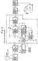
- Fig. 3 is a block diagram of a robot controlling apparatus in accordance with third and fourth preferred embodiments of the invention.
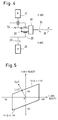
- Fig. 4 is a diagrammatic mechanism view of axis interference in two axes.
- Fig. 5 is an axis velocity relation diagram where axis interference takes place.
- Fig. 6 is a block diagram of a robot controlling apparatus known in the art.
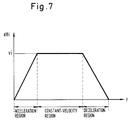
- Fig. 7 illustrates the acceleration/deceleration control of the robot controlling apparatus shown in Fig. 6.
- Fig. 1 is a block diagram showing the configuration of a robot controlling apparatus.
- the numeral 4 indicates a position controller comprising a maximum velocity character generator section 11 for generating a maximum velocity character S, an axis load factor generator section 12 as axis load factor calculating means for generating the load factor ni of each axis, a permissible interpolation travel velocity generator section 13 as permissible interpolation travel velocity calculating means for generating a permissible interpolation travel velocity U, a velocity command generator section 6 as velocity command calculating means for generating a velocity command d ⁇ i for each axis at intervals of time ⁇ t, and a position command generator section 7 as transmitted command calculating means for generating a position command ⁇ i at intervals of time ⁇ t on the basis of the velocity command d ⁇ i .
- a subtracter 10 is used as travel value calculator for outputting a difference between the target position information ⁇ id (hereinafter referred to as the "target position") of each axis generated by a target position generator section 3 and the position command ⁇ i of each axis output by the position command generator section 7 as the travel value ⁇ i of each axis in corresponding sampling synchronization.
- an instruction decoder section 2 initiates the decoding of instructions in that program.
- information obtained by the instruction decoding is an instruction concerned with the traveling operation of the robot R
- the instruction decoder section 2 commands the target position generator section 3 to generate a target position ⁇ id .
- This command causes the target position generator section 3 to generate the target position ⁇ id as the target position information of each axis.
- the axis load factor n i is a non-dimensional quantity, representing a travel load (difficulty in moving) in the travel of each axis.
- the load factor will have a minimum value of 1 for the fastest axis and will have greater values for slower axes that move with greater difficulty.
- the velocity command generator section 6 in the position controller 4 performs velocity control and locus control regarding the traveling operation of the robot on the basis of the target position ⁇ id , axis load factor ni and permissible interpolation travel velocity U.
- the velocity control and locus control are exercised by sampling control. Namely, the following processing is carried out at intervals of certain time ⁇ t, generating the velocity command d ⁇ i .
- the axis travel distance Li will be larger where the axis has a larger travel load (difficulty in moving), as indicated by a value of n i greater than 1.
- a typical travel distance Lm is then generated. Namely, the maximum value of the travel distance L i of each axis is defined as the typical travel distance L m .
- L m max ⁇ L i ⁇ (15)
- a travel velocity character dV in next ⁇ t time is then calculated from the given acceleration velocity A and deceleration velocity D common to each axis and the permissible interpolation travel velocity U. That is, an acceleration region, a constant-velocity region or a deceleration region is judged on the basis of the typical travel distance Lm calculated per ⁇ t time, the permissible interpolation travel velocity U, the acceleration velocity A and the deceleration velocity D.
- the velocity command d ⁇ i of each axis in the next ⁇ t time d ⁇ i is then be calculated from the velocity character dV common to each axis.
- d ⁇ i dV ⁇ i /L m (19)
- the coordinate converter section 8 converts the position command ⁇ i into the number of drive motor pulses J i of each axis of the robot R and passes the result to the positioning controller section 9.
- the positioning controller section 9 outputs the number of drive motor pulses Ji of each axis to each axis motor of the robot R via a built-in digital-to-analog converter.
- the robot R repeats the above operation until the target position is reached, thereby completing the movement to the target position.
- expressions (10) to (20) are all those of vector calculation, i.e. vector calculations may only be made a total of five times per axis at intervals of the sampling period. As compared to the conventional approach shown in Fig. 6, therefore, the number of calculations are reduced, requiring shorter processing time for a robot having many articulated axes.
- the robot can be controlled consistently.
- Fig. 2 shows the configuration of an embodiment of the invention with the feature, wherein 3A indicates an additional axis target position generator section for generating a position variable ⁇ aid which is the target position of an additional axis.
- Position controller 4A comprises a maximum velocity character generator section 11A for generating a maximum velocity character S, an axis load factor generator section 12A for generating the load factor n i of each robot axis and the load factor n ai of each additional axis, a permissible interpolation travel velocity generator section 13 for generating a permissible interpolation travel velocity U, a velocity command generator section 6A for generating a velocity command d ⁇ i for each robot axis and a velocity command d ⁇ ai for each additional axis at intervals of ⁇ t time, a position command generator section 7 for generating a position command ⁇ i at intervals of ⁇ t time on the basis of the velocity command d ⁇ i , and an additional axis position command generator section 7A for generating an additional axis position command ⁇ ai at intervals of ⁇ t time on the basis of the velocity command d ⁇ ai .
- the position command calculating means comprises the position command generator section 7 and additional
- An additional axis coordinate converter section 8A is used for converting the additional axis position command ⁇ ai generated by the position controller 4A into the number of drive motor pulses J ai of each additional axis.
- An additional axis positioning controller section 9A is used for positioning each additional axis on the basis of the number of drive motor pulses J ai .
- an instruction decoder section 2 starts decoding instructions in that program.
- information obtained by the instruction decoding is an instruction concerned with the traveling operation of the robot
- the instruction decoder section 2 commands the target position generator section 3 and additional axis target position generator section 3A to generate respective target positions ⁇ id and ⁇ aid .
- This command causes the target position generator section 3 and additional axis target position generator section 3A to generate the target positions ⁇ id and ⁇ aid .
- the maximum velocity character generator section 11A in the position controller 4A obtains a maximum velocity character S from the maximum values of a maximum permissible axis angular velocity ⁇ im stipulated from the drive motor of each robot axis and a maximum permissible additional axis angular velocity ⁇ aim stipulated from the drive motor of each additional axis.
- S max ⁇ im , ⁇ aim ⁇ (21)
- the axis load factor generator section 12 in the position controlling means 4A calculates a robot axis load factor n i and an additional axis load factor n ai from the maximum permissible axis angular velocity ⁇ im , maximum permissible additional axis angular velocity ⁇ aim and maximum velocity character S.
- n i S/ ⁇ im
- n ai S/ ⁇ aim
- axis load factors n i and n ai are non-dimensional quantities, each representing a travel load (difficulty in moving) in the travel of each axis.
- the permissible interpolation travel velocity generator section 13 in the position controlling means 4A calculates a permissible interpolation travel velocity U from the maximum velocity character S and an override factor O v .
- U O v ⁇ S (24)
- the velocity command generator section 6A in the position controlling means 4A performs velocity control and locus control related to the traveling operation of the robot on the basis of the target positions ⁇ id and ⁇ aid , axis load factors n i and n ai , and permissible interpolation travel velocity U.
- the velocity control and locus control are carried out by sampling control. That is, the following processing is performed at intervals of certain time ⁇ t, generating the velocity commands d ⁇ i , d ⁇ ai .
- the axis travel distances L i , L ai become larger as the axes have a larger travel load (difficulty in moving).
- L m max ⁇ L i ,L ai ⁇ (29)
- a travel velocity character dV in the next ⁇ t time is then calculated from the given acceleration velocity A and deceleration velocity D of each axis and the permissible interpolation travel velocity U. Namely, an acceleration region, a constant-velocity region or a deceleration region is judged on the basis of the typical travel distance L m calculated per ⁇ t time, the permissible interpolation travel velocity U, the acceleration velocity A and the deceleration velocity D.
- the coordinate converter section 8 converts the position command ⁇ i into the number of drive motor pulses J i of each axis of the robot and passes the result to the positioning controller section 9, which then outputs the number of drive motor pulses J i of each axis to each axis of the robot via a built-in digital-to-analog converter.
- the additional axis coordinate converter section 17 converts said additional axis position command ⁇ ai into the number of drive motor pulses J ai of each additional axis and passes the result to the additional axis positioning controller section 18, which then outputs the number of additional axis drive motor pulses J ai to each additional axis via the built-in digital-to-analog converter.
- the robot and additional axes repeat the above operation until the target positions are reached, thereby completing the movement to the target positions.
- the present embodiment has the maximum velocity character for velocity control and includes the load factor vector of each operating axis calculated on the basis of the maximum velocity character as described above, a typical travel distance D max and a travel velocity v can be calculated and velocity interpolation can be performed on the basis of such calculations, which not only simplifies processing and reduces processing time but also facilitates synchronous control of the additional axes with the robot axes when the robot and additional axes are to be controlled simultaneously.
- the third embodiment includes an axis load factor changing section for changing the axis load factors n i and/or n ai on the basis of axis interference information, thereby allowing control to be exercised to cope with axis interference in a plurality of robot axes.
- Fig. 3 is a block diagram illustrating the arrangement of a robot controlling apparatus of the third embodiment.
- This robot controlling apparatus is different from the one shown in Fig. 1 in that axis load factors n i generated by the axis load factor generator section 12B in the position controlling means 4B are changed by the axis load factor changing section 14, serving as an axis load factor changing means.
- Axis interference information is entered into the axis load factor changing section 14.
- Axis interference takes place in a joint having a mechanism as shown in Fig. 4, which is a diagrammatic mechanism view of axis interference.
- 20 indicates a u axis, 21 a u-axis drive motor, 30 a v axis, 31 a v-axis drive motor, and 32 and 33 bevel gears for transmitting the rotation of the v-axis drive motor 31 to the v axis 30.
- the v axis 30 rotates in the direction of an arrow 34 if the v-axis drive motor 31 is kept stopped. Namely, the rotation of the u axis 20 in the direction of the arrow 22 is added as the rotation of the v axis 30 in the direction of the arrow 34.
- a permissible velocity for rotating the v axis 30 by the v-axis drive motor 31 varies according to the velocity of the u axis 20, as indicated in an axis velocity relation diagram of Fig. 5.
- the p and vo in the expression (37) are the axis interference information. It should be noted that supposing the permissible velocity of the u axis 20 is uo, a velocity (u, v) must be within the region of a parallelogram in Fig. 4.
- the velocity commands u', v' are found in the following procedure. For example, if the travel velocity is as indicated by (u, v) in Fig. 4, (u, v) is reduced toward the zero (0, 0) and a velocity (u', v') falling within the parallelogram region is adopted. Alternatively, a perpendicular is dropped from (u, v) to the side of the parallelogram and a velocity (u', v') located on that side is adopted.
- n ⁇ '
- n ⁇ '
- a command is then given to the axis load factor generator section 12 to change the load factors n ⁇ , n ⁇ of the interferable axes ⁇ , ⁇ into n ⁇ ', n ⁇ '.
- the velocity commands d ⁇ i falling within the parallelogram region are automatically generated, and if the robot includes interferable axes, it can carry out smooth velocity control easily.
- axis factor changing section 14 added to the robot controlling apparatus shown in Fig. 1 to change the axis load factors of a plurality of axes of the robot R in the axis load factor changing section 14 to cope with axis interference
- an identical effect can be produced on a robot which includes additional axes to the robot axes shown in Fig. 2 by the addition of an axis load factor changing section for the additional axes which exercises similar control.
Landscapes
- Engineering & Computer Science (AREA)
- Human Computer Interaction (AREA)
- Manufacturing & Machinery (AREA)
- Physics & Mathematics (AREA)
- General Physics & Mathematics (AREA)
- Automation & Control Theory (AREA)
- Numerical Control (AREA)
- Manipulator (AREA)
Abstract
Description
- The present invention relates to a robot controlling apparatus and method therefor, and more particularly to a robot controlling apparatus and method which can simplify calculations of velocity commands.
- An example of a robot controlling apparatus known in the art is shown in Fig. 6, wherein a program and
data storage section 1 is used for storing user-written programs and position variable data generated by teaching or manual data input. Aninstruction decoder section 2 is connected for decoding the instructions of a program read from theprogram storage section 1, and supplying decoded instructions to a targetposition generator section 3, which generates a position variable ϑid which represents a target position when the instruction decoded is concerned with a traveling operation. Each axis i of a robot R may be separately identified, e.g. i = 1, 2, 3, 4, 5, 6 for a six-axis robot. The movement of the robot along each axis is specified in terms of a rotational movement for purposes of explanation, since movement ordinarily is provided by a motor. - A
position controller 54, comprising a permissible axis travelvelocity generator section 55 for generating a permissible axis travel velocity ωi, a velocitycommand generator section 56 for generating a velocity command dϑi for each axis at intervals of Δt time, and a position command generator section 7 that is responsive to the velocity command dϑi , is operative to generate a position command ϑi at intervals of Δt time. Acoordinate converter section 8 converts the position command ϑi generated by theposition controller 54 into an appropriate number of drive motor pulses Ji of each axis of the robot R. Apositioning controller section 9 is responsive to the number of drive motor pulses Ji and positions each of the corresponding i axes of the robot R accordingly. Asubtracter 10 is responsive to the target value ϑid and calculated value ϑic output from command generator section 7 to generate a difference travel value Δϑi for each axis. - The operation of the robot controlling apparatus will now be described. When a program is selected to be executed from among a plurality of programs stored in the
program storage device 1, theinstruction decoder section 2 initiates the decoding of instructions in that program. When information obtained by the instruction decoding is an instruction concerned with the traveling operation of the robot R, theinstruction decoder section 2 commands the targetposition generator section 3 to generate a target position ϑid. This command causes the targetposition generator section 3 to generate the target position ϑid. - The permissible axis travel
velocity generator section 55 in theposition controller 54 calculates a permissible axis travel velocity ωi from a maximum permissible axis angular velocity ωim stipulated from the drive motor of each axis and an override factor (specified by a percentage of the maximum permissible angular velocity) Ov:

- The velocity
command generator section 56 in theposition controller 54 performs velocity control and locus control concerned with the traveling operation of the robot in accordance with the target position ϑid and permissible axis travel velocity ωi. - The velocity control and locus control are carried out by sampling control, i.e. the following processing is performed at intervals of certain time Δt, generating the velocity command dϑi.
- First, the travel value Δϑi of each axis is calculated from the target position ϑid and a preceding position command ϑi (for convenience of explanation, this is represented as ϑic):

- Travel time ti of each axis is then calculated from the travel value Δϑi and permissible axis travel velocity ωi of each axis:

- The maximum travel time for all axes is then identified:

- In the meantime, to start the travel of each axis simultaneously and terminate the travel at the same time, all the axes are moved with their respective travel values Δϑi during that travel time ti which is a maximum value. Hence, the permissible axis travel velocity of each axis is compensated for to calculate a maximum axis interpolation velocity Vi:

- A velocity command dϑi in the next Δt time is then calculated from the given acceleration velocity ai and deceleration velocity di of each axis and the maximum axis interpolation velocity Vi. Namely, supposing that the velocity of each axis is controlled as shown in Fig. 7 which illustrates acceleration/deceleration control, the next velocity command dϑi is found as follows, judging from a preceding velocity command dϑic and the remaining travel value, if the area of the next velocity command dϑi is an acceleration region:

where an initial value is zero. - If that area is a constant-velocity region:

- If it is a deceleration region:

- The velocity command dϑi is generated as described above.
- The position command generator section 7 in the
position controller 54 generates the position command ϑi of each axis in the next Δt time according to the velocity command dϑi:

- The
coordinate converter section 8 converts the position command ϑi into the number of drive motor pulses Ji of each axis of the robot R and passes the result to thepositioning controller section 9. Thepositioning controller section 9 outputs the number of drive motor pulses Ji of each axis to the motor of each axis of the robot R via a built-in digital-to-analog converter. This moves the robot R to the position of the position command ϑi. - With the exception of expression (4), the expressions (1) to (9) are all those of vector calculation. That is, vector calculations are made a total of eight times per sampling. In the robot controlling apparatus of the backgound art, therefore, the greater the number of articulated axes that the robot has, the more calculations it has to make, taking much processing time. Also, where target positions in a three-dimensional space represented by a cartesian coordinate system are to be generated or target positions in a three-dimensional space represented by a cylindrical coordinate system are to be generated (interpolation in a three-dimensional space system), the robot cannot be controlled consistently since the concepts of interpolation velocities in such coordinate systems differ from each other. Further, control will be complex in an articulate mechanism where axis interference occurs.
- As another related background art, there is a robot controlling process disclosed in Japanese Patent Disclosure Publication No. 262212 of 1985. This controlling process determines a velocity by multiplying a maximum permissible velocity by a velocity factor calculated according to the parameters of a corner on the traveling path of a robot. However, the robot controlling process disclosed in Japanese Patent Disclosure Publication No. 262212 of 1985 is designed for a traveling operation at a corner and is not appropriate for the control of a general traveling operation.
- In the conventional robot controlling apparatus described as constructed above, calculations for velocity and position controls increase for a robot having many articulated axes, taking much processing time. Further, when axes outside the robot (additional axes) as well as the robot's axes are to be controlled by a single controlling apparatus, not only are the number of calculations increased but the travels of the robot axes must be synchronized with those of the additional axes.
- It is accordingly an object of the present invention to overcome the disadvantages in the background art by providing a robot controlling apparatus and method which allows calculations to be simplified and velocity and position controls to be exercised easily.
- Another object of the present invention is to provide a robot controlling apparatus and method that also allows calculations to be simplified and velocity and position controls to be carried out easily for additional axes, as where the robot includes both robot axes and such additional axes.
- The first embodiment achieves a robot controlling apparatus and method that simplifies the positioning operation of each axis of a robot through the entry of the target position information of each axis, thereby facilitating velocity and position controls for a robot having many articulated axes. The first embodiment includes a position controller which defines the maximum value of the maximum permissible velocity of each axis of the robot as a maximum velocity character, calculates the load factor of each axis on the basis of the maximum velocity character, calculates the travel value of each axis from the target position information and preceding position command of said each axis, finds the travel distance of each axis from the travel value and load factor of each axis, defines the maximum value of travel distance as a typical travel distance, calculates a travel velocity character common to each axis from an acceleration velocity and a deceleration velocity common to each axis and a permissible interpolation travel velocity, calculates the velocity command of each axis from the travel velocity character and the travel value of the each axis, and calculates the position command of each axis on the basis of the velocity command of each axis.
- The present invention achieves a robot controlling apparatus and method which simplifies the positioning operation of synchronizing additional axes with robot axes, facilitating velocity and position controls for a robot having additional axes besides the robot axes. The invention includes a position controller which outputs the position command of each of the robot axes and the additional axes through the entry of the target position information of each axis.
- The invention also achieves a robot controlling apparatus that prevents excessive velocity in an articulated mechanism having interferable axes, facilitating velocity and position controls. The invention includes axis load factor changing means for changing the load factor of each axis comprising a plurality of robot axes or robot axes and additional axes. The invention also includes axis load factor changing means that changes the load factor of each operational axis, comprising any of a plurality of robot axes or a combination of robot axes and additional axes, on the basis of information on the axis interference of a robot.
- Fig. 1 is a block diagram of a robot controlling apparatus in accordance with a first preferred embodiment of the invention.
- Fig. 2 is a block diagram of a robot controlling apparatus in accordance with a second preferred embodiment of the invention.
- Fig. 3 is a block diagram of a robot controlling apparatus in accordance with third and fourth preferred embodiments of the invention.
- Fig. 4 is a diagrammatic mechanism view of axis interference in two axes.
- Fig. 5 is an axis velocity relation diagram where axis interference takes place.
- Fig. 6 is a block diagram of a robot controlling apparatus known in the art.
- Fig. 7 illustrates the acceleration/deceleration control of the robot controlling apparatus shown in Fig. 6.
- A first embodiment of the invention will now be described with reference to Fig. 1, wherein parts designated by reference characters in the background art indicate like or corresponding ones.
- Fig. 1 is a block diagram showing the configuration of a robot controlling apparatus. Referring to Fig. 1, the
numeral 4 indicates a position controller comprising a maximum velocitycharacter generator section 11 for generating a maximum velocity character S, an axis loadfactor generator section 12 as axis load factor calculating means for generating the load factor ni of each axis, a permissible interpolation travelvelocity generator section 13 as permissible interpolation travel velocity calculating means for generating a permissible interpolation travel velocity U, a velocitycommand generator section 6 as velocity command calculating means for generating a velocity command dϑi for each axis at intervals of time Δt, and a position command generator section 7 as transmitted command calculating means for generating a position command ϑi at intervals of time Δt on the basis of the velocity command dϑi. Asubtracter 10 is used as travel value calculator for outputting a difference between the target position information ϑid (hereinafter referred to as the "target position") of each axis generated by a targetposition generator section 3 and the position command ϑi of each axis output by the position command generator section 7 as the travel value Δϑi of each axis in corresponding sampling synchronization. - The operation of the robot controlling apparatus according to the first embodiment will now be described. When a program is selected to be executed from among a plurality of programs stored in a
program storage device 1, aninstruction decoder section 2 initiates the decoding of instructions in that program. When information obtained by the instruction decoding is an instruction concerned with the traveling operation of the robot R, theinstruction decoder section 2 commands the targetposition generator section 3 to generate a target position ϑid. This command causes the targetposition generator section 3 to generate the target position ϑid as the target position information of each axis. - The maximum velocity
character generator section 11 in theposition controller 4 obtains a maximum velocity character S from the maximum value of a maximum permissible axis angular velocity ωim stipulated for the drive motor of each axis.

- The axis load
factor generator section 12 in theposition controller 4 calculates for each axis an axis load factor ni from the maximum permissible axis angular velocity ωim and the maximum velocity character S.

- The axis load factor ni is a non-dimensional quantity, representing a travel load (difficulty in moving) in the travel of each axis. The load factor will have a minimum value of 1 for the fastest axis and will have greater values for slower axes that move with greater difficulty.
- The permissible interpolation travel
velocity generator section 13 in theposition controller 4 calculates a permissible interpolation travel velocity U from the maximum velocity character S and a specified override factor Ov. Note that this single calculation is relatively simple, as compared to the calculation in the background are which requires each axis to be considered.

- The velocity
command generator section 6 in theposition controller 4 performs velocity control and locus control regarding the traveling operation of the robot on the basis of the target position ϑid, axis load factor ni and permissible interpolation travel velocity U. - The velocity control and locus control are exercised by sampling control. Namely, the following processing is carried out at intervals of certain time Δt, generating the velocity command dϑi. First, the travel value Δϑi of each axis is calculated from the target position ϑid and a preceding position command ϑic:

- An axis travel distance Li is then calculated by multiplying the travel value Δϑi of each axis by the axis load factor ni:

- For a given travel value Δϑi, the axis travel distance Li will be larger where the axis has a larger travel load (difficulty in moving), as indicated by a value of ni greater than 1.
- A typical travel distance Lm is then generated. Namely, the maximum value of the travel distance Li of each axis is defined as the typical travel distance Lm.

- A travel velocity character dV in next Δt time is then calculated from the given acceleration velocity A and deceleration velocity D common to each axis and the permissible interpolation travel velocity U. That is, an acceleration region, a constant-velocity region or a deceleration region is judged on the basis of the typical travel distance Lm calculated per Δt time, the permissible interpolation travel velocity U, the acceleration velocity A and the deceleration velocity D. When in the acceleration region, the travel velocity character dV in the next Δt time is as follows:

where an initial value is zero. - When in the constant-velocity region:

- When in the deceleration region:

- The velocity command dϑi of each axis in the next Δt time dϑi is then be calculated from the velocity character dV common to each axis.

- The position command generator section 7 in the position controlling means 4 generates the position command ϑi of each axis in next Δt time according to the velocity command dϑi:

- The coordinate
converter section 8 converts the position command ϑi into the number of drive motor pulses Ji of each axis of the robot R and passes the result to thepositioning controller section 9. Thepositioning controller section 9 outputs the number of drive motor pulses Ji of each axis to each axis motor of the robot R via a built-in digital-to-analog converter. - The robot R repeats the above operation until the target position is reached, thereby completing the movement to the target position.
- Among the expressions (10) to (20), expressions (11), (13), (14), (19) and (20) are all those of vector calculation, i.e. vector calculations may only be made a total of five times per axis at intervals of the sampling period. As compared to the conventional approach shown in Fig. 6, therefore, the number of calculations are reduced, requiring shorter processing time for a robot having many articulated axes.
- Further, where target positions in a three-dimensional space represented by a cartesian coordinate system are to be generated or target positions in a three-dimensional space represented by a cylindrical coordinate system are to be generated from the target position generator 3 (interpolation in a three-dimensional space system), the robot can be controlled consistently.
- A second feature of the invention will now be described with reference to Fig. 2. With this feature, the axes internal to the robot and additional axes external to the robot may be synchronized and commonly controlled.
- Fig. 2 shows the configuration of an embodiment of the invention with the feature, wherein 3A indicates an additional axis target position generator section for generating a position variable ϑaid which is the target position of an additional axis. The subscript a indicates a variable or value concerned with the additional axis, and i represents each of the robot and additional axes, e.g. i in ϑid = 1, 2, 3, 4, 5, 6 and i in ϑaid = 1, 2 for a six-axis robot having two additional axes.
- Position controller 4A comprises a maximum velocity
character generator section 11A for generating a maximum velocity character S, an axis loadfactor generator section 12A for generating the load factor ni of each robot axis and the load factor nai of each additional axis, a permissible interpolation travelvelocity generator section 13 for generating a permissible interpolation travel velocity U, a velocitycommand generator section 6A for generating a velocity command dϑi for each robot axis and a velocity command dϑai for each additional axis at intervals of Δt time, a position command generator section 7 for generating a position command ϑi at intervals of Δt time on the basis of the velocity command dϑi, and an additional axis positioncommand generator section 7A for generating an additional axis position command ϑai at intervals of Δt time on the basis of the velocity command dϑai. The position command calculating means comprises the position command generator section 7 and additional axis positioncommand generator section 7A. - An additional axis coordinate
converter section 8A is used for converting the additional axis position command ϑai generated by the position controller 4A into the number of drive motor pulses Jai of each additional axis. An additional axispositioning controller section 9A is used for positioning each additional axis on the basis of the number of drive motor pulses Jai. - The operation of the robot controlling apparatus according to the present embodiment will now be described. Referring to Fig. 2, when a program is selected to be run from among a plurality of programs stored in a
program storage device 1, aninstruction decoder section 2 starts decoding instructions in that program. When information obtained by the instruction decoding is an instruction concerned with the traveling operation of the robot, theinstruction decoder section 2 commands the targetposition generator section 3 and additional axis targetposition generator section 3A to generate respective target positions ϑid and ϑaid. This command causes the targetposition generator section 3 and additional axis targetposition generator section 3A to generate the target positions ϑid and ϑaid. - The maximum velocity
character generator section 11A in the position controller 4A obtains a maximum velocity character S from the maximum values of a maximum permissible axis angular velocity ωim stipulated from the drive motor of each robot axis and a maximum permissible additional axis angular velocity ωaim stipulated from the drive motor of each additional axis.

- The axis load
factor generator section 12 in the position controlling means 4A calculates a robot axis load factor ni and an additional axis load factor nai from the maximum permissible axis angular velocity ωim, maximum permissible additional axis angular velocity ωaim and maximum velocity character S.


- The axis load factors ni and nai are non-dimensional quantities, each representing a travel load (difficulty in moving) in the travel of each axis.
- The permissible interpolation travel
velocity generator section 13 in the position controlling means 4A calculates a permissible interpolation travel velocity U from the maximum velocity character S and an override factor Ov.

- The velocity
command generator section 6A in the position controlling means 4A performs velocity control and locus control related to the traveling operation of the robot on the basis of the target positions ϑid and ϑaid, axis load factors ni and nai, and permissible interpolation travel velocity U. The velocity control and locus control are carried out by sampling control. That is, the following processing is performed at intervals of certain time Δt, generating the velocity commands dϑi, dϑai. - First, the travel value Δϑi of each robot axis is calculated from the target position ϑid and a preceding position command ϑic:

- Similarly, the travel value is also calculated for each additional axis:

- Axis travel distances Li, Lai are then calculated by multiplying the travel values Δϑi, Δϑai of each axis by the axis load factors ni, nai, respectively:


- For given travel values Δϑi or Δϑi, the axis travel distances Li, Lai become larger as the axes have a larger travel load (difficulty in moving).
- A typical travel distance Lm is then generated.

- A travel velocity character dV in the next Δt time is then calculated from the given acceleration velocity A and deceleration velocity D of each axis and the permissible interpolation travel velocity U. Namely, an acceleration region, a constant-velocity region or a deceleration region is judged on the basis of the typical travel distance Lm calculated per Δt time, the permissible interpolation travel velocity U, the acceleration velocity A and the deceleration velocity D. When in the acceleration region, the travel velocity character dV in the next Δt time is as follows:

where an initial value is zero. - When in the constant-velocity region:

- When in the deceleration region:

- The travel velocity dϑi of each axis and travel velocity dϑai of each additional axis in next Δt time are then calculated from the velocity character dV common to each axis:


- The position command generator section 7 in the position controlling means 4 generates the position command ϑi of each axis in next Δt time according to the velocity command dϑi:

- Similarly, the additional axis position command generator section 16 generates the additional axis position command dϑai in next Δt time according to the additional axis velocity command dϑai:

- The coordinate
converter section 8 converts the position command ϑi into the number of drive motor pulses Ji of each axis of the robot and passes the result to thepositioning controller section 9, which then outputs the number of drive motor pulses Ji of each axis to each axis of the robot via a built-in digital-to-analog converter. - Similarly, the additional axis coordinate converter section 17 converts said additional axis position command ϑai into the number of drive motor pulses Jai of each additional axis and passes the result to the additional axis positioning controller section 18, which then outputs the number of additional axis drive motor pulses Jai to each additional axis via the built-in digital-to-analog converter.
- The robot and additional axes repeat the above operation until the target positions are reached, thereby completing the movement to the target positions.
- Since the present embodiment has the maximum velocity character for velocity control and includes the load factor vector of each operating axis calculated on the basis of the maximum velocity character as described above, a typical travel distance Dmax and a travel velocity v can be calculated and velocity interpolation can be performed on the basis of such calculations, which not only simplifies processing and reduces processing time but also facilitates synchronous control of the additional axes with the robot axes when the robot and additional axes are to be controlled simultaneously.
- Further features of third and fourth embodiments will now be described with reference to Figs. 3 to 5. In addition to the robot controlling apparatus of the first embodiment shown in Fig. 1, the third embodiment includes an axis load factor changing section for changing the axis load factors ni and/or nai on the basis of axis interference information, thereby allowing control to be exercised to cope with axis interference in a plurality of robot axes.
- Fig. 3 is a block diagram illustrating the arrangement of a robot controlling apparatus of the third embodiment. This robot controlling apparatus is different from the one shown in Fig. 1 in that axis load factors ni generated by the axis load
factor generator section 12B in the position controlling means 4B are changed by the axis loadfactor changing section 14, serving as an axis load factor changing means. Axis interference information is entered into the axis loadfactor changing section 14. - Axis interference takes place in a joint having a mechanism as shown in Fig. 4, which is a diagrammatic mechanism view of axis interference. Referring to Fig. 4, 20 indicates a u axis, 21 a u-axis drive motor, 30 a v axis, 31 a v-axis drive motor, and 32 and 33 bevel gears for transmitting the rotation of the v-
axis drive motor 31 to thev axis 30. - When the
u axis 20 is rotated in the direction of anarrow 22 in the illustrated articulated mechanism, thev axis 30 rotates in the direction of anarrow 34 if the v-axis drive motor 31 is kept stopped. Namely, the rotation of theu axis 20 in the direction of thearrow 22 is added as the rotation of thev axis 30 in the direction of thearrow 34. Hence, a permissible velocity for rotating thev axis 30 by the v-axis drive motor 31 varies according to the velocity of theu axis 20, as indicated in an axis velocity relation diagram of Fig. 5. - That is, the permissible velocity v of the
v axis 30 is as follows, assuming that the directions of thearrows

where p is an interference factor, u is a u axis velocity, and vo is the permissible velocity of the v axis at the u axis velocity of zero. The p and vo in the expression (37) are the axis interference information. It should be noted that supposing the permissible velocity of theu axis 20 is uo, a velocity (u, v) must be within the region of a parallelogram in Fig. 4. - The axis load
factor changing section 14 calculates Δϑi and Lm according to previously described expression (13):

and expression (15):

- Further, assuming that axis identifier (i) of interferable axes are α and β, the velocity commands u and v of the interferable axes α and β are calculated by the following expressions:


- It is then checked whether or not the velocity commands u, v calculated are within the region of the parallelogram shown in Fig. 4. If they are within the parallelogram region, the axis load factors ni are not changed. If they are not within the parallelogram region, velocity commands u', v' falling within the parallelogram region are found.
- The velocity commands u', v' are found in the following procedure. For example, if the travel velocity is as indicated by (u, v) in Fig. 4, (u, v) is reduced toward the zero (0, 0) and a velocity (u', v') falling within the parallelogram region is adopted. Alternatively, a perpendicular is dropped from (u, v) to the side of the parallelogram and a velocity (u', v') located on that side is adopted.
- Then, supposing that the load factors of the interferable axes α, β are nα and nβ, respectively, nα' and nβ' are calculated by the following expressions:


- A command is then given to the axis load
factor generator section 12 to change the load factors nα, nβ of the interferable axes α, β into nα', nβ'. - By employing the new axis load factors ni, the velocity commands dϑi falling within the parallelogram region are automatically generated, and if the robot includes interferable axes, it can carry out smooth velocity control easily.
- While the present embodiment described above has the axis
factor changing section 14 added to the robot controlling apparatus shown in Fig. 1 to change the axis load factors of a plurality of axes of the robot R in the axis loadfactor changing section 14 to cope with axis interference, an identical effect can be produced on a robot which includes additional axes to the robot axes shown in Fig. 2 by the addition of an axis load factor changing section for the additional axes which exercises similar control. - The entire disclosure of each and every foreign patent application from which the benefit of foreign priority has been claimed in the present application is incorporated herein by reference, as if fully set forth.
- Although this invention has been described in at least one preferred form with a certain degree of particularity, it is to be understood that the present disclosure of the preferred embodiments has been made only by way of example and that numerous changes in the details and arrangement of components may be made without departing from the spirit and scope of the invention as hereinafter claimed.
Claims (20)
- A robot controlling apparatus including position controlling means for outputting position commands for each axis of a robot according to the input of the target position information for said each axis, said position controlling means comprising:
axis load factor calculating means for finding the maximum value of the maximum permissible velocity of said each axis as a maximum velocity character and calculating a ratio of the maximum permissible velocity of said each axis to said maximum velocity character as the load factor of said each axis;
permissible interpolation travel velocity calculating means for calculating a permissible interpolation travel velocity from said maximum velocity character and an override factor;
travel value calculating means for calculating the travel value of said each axis from a difference between said target position and a preceding position command of said each axis;
velocity command calculating means for finding the travel distance of said each axis as a product of the travel value and load factor of said each axis, defining the maximum value of said travel distance as a typical travel distance, calculating a travel velocity character in at least one of an acceleration region, a constant-velocity region or a deceleration region common to said each axis and said permissible interpolation travel velocity, and calculating a velocity command for said each axis from a ratio of a product of said travel velocity character and the travel value of said each axis to said typical travel distance; and
position command calculating means for calculating a position command for said each axis from the velocity command for said each axis. - A robot controlling apparatus as defined in claim 1, wherein said first plurality of axes comprises robot axes within a robot and additional axes outside the robot and wherein said additional axes are position controlled in synchronization with said robot axes.
- A robot controlling apparatus as defined in claim 1 or claim 2, further comprising axis load factor changing means for changing the load factors of the robot axes or of the robot axes and additional axes calculated by said axis load factor calculating means.
- A robot controlling apparatus as defined in claim 3, wherein said axis load factor changing means changes the load factors of said first plurality of axes as calculated by said axis load factor calculating means on the basis of information on the interference of the robot axes.
- A robot controlling apparatus as defined in claim 3 wherein all said axes are controlled according to the same velocity profile.
- A robot controlling apparatus including position controlling means for outputting position commands for each axis of a robot according to the input of the target position information for said each axis, said position controlling means comprising:
means for selecting a baseline velocity value and baseline velocity profile;
means for generating a respective load factor for said each axis on the basis of a velocity value for said each axis and said baseline velocity value;
first means responsive to at least said respective load factor and said baseline velocity profile for generating for each axis a velocity command; and
second means responsive to said velocity command for generating a position command for said each axis. - The robot controlling apparatus of claim 6 wherein said first responsive means is responsive to a differential travel value and a factored velocity value for said each axis and said position controlling means further comprises:
means for calculating a factored velocity value on the basis of an override factor; and
means for calculating a differential travel value on the basis of said target position and a preceeding position along said each axis. - The robot controlling apparatus of claim 6 wherein said generating means further comprises means for changing the load factor for at least one of said axes.
- The robot controlling apparatus of claim 6 wherein said baseline veliocity profile is identical for plural ones of said axes.
- A method of controlling a robot having a plurality of movement axes comprising:
inputting target position information for each of a first plurality of said movement axes;
calculating the maximum value of the maximum permissible velocity of each first plurality axis as a maximum velocity character;
calculating a ratio of the maximum permissible velocity of each first plurality axis to said maximum velocity character as the load factor of each said first plurality axis;
calculating a permissible interpolation travel velocity from said maximum velocity character and an override factor;
calculating the travel value of each said first plurality axis from a difference between said target position and a preceding position command of said each axis;
determining the travel distance of each said first plurality axis as a product of the travel value and load factor of said each axis;
defining the maximum value of said travel distance as a typical travel distance;
calculating a travel velocity character in an acceleration region, a constant-velocity region or a deceleration region common to each said first plurality axis from a acceleration velocity and a deceleration velocity common to said each axis and said permissible interpolation travel velocity;
calculating a velocity command for each said first plurality axis from a ratio of a product of said travel velocity character and the travel value of said each axis to said typical travel distance;
calculating a position command for each said first plurality axis from the velocity command for said each axis; and
outputting position commands for each said first plurality axis according to said input target position information. - The method of Claim 10 wherein all of said first plurality of axes are controlled according to the same velocity profile.
- The method of claim 10 wherein said first plurality of movement axes comprises movement axes within a robot and additional axes outside the robot and said input target position information of said each axis is operative to position-control said additional axes in synchronization with said robot axes.
- The method of claim 10 further comprising:
modifying said load factor on the basis of interference between axes. - A method of controlling a robot system comprising a robot having a plurality of movement axes and a position controlling means for outputting position commands for each axis of said robot according to the input of the target position information of said each axis, said method comprising:
selecting one of a first plurality of said movement axes having a maximum velocity;
defining the velocity of a second plurality of said movement axes with respect to said maximum velocity;
calculating the maximum value of the maximum permissible velocity of each first plurality axis as a maximum velocity character;
calculating a ratio of the maximum permissible velocity of each first plurality axis to said maximum velocity character as the load factor of each said first plurality axis;
calculating a permissible interpolation travel velocity from said maximum velocity character;
calculating the travel value of each said first plurality axis from a difference between said target position and a preceding position command of said each axis;
determining the travel distance of each said first plurality axis as a product of the travel value and load factor of said each axis;
defining the maximum value of said travel distance as a typical travel distance;
calculating a travel velocity character in an acceleration region, a constant-velocity region or a deceleration region common to each said first plurality axis from a acceleration velocity and a deceleration velocity common to said each axis and said permissible interpolation travel velocity;
calculating a velocity command for each said first plurality axis from a ratio of a product of said travel velocity character and the travel value of said each axis to said typical travel distance;
calculating a position command for each said first plurality axis from the velocity command for said each axis; and
outputting position commands for each said first plurality axis according to said input target position information. - A robot controlling method as defined in claim 14, wherein said axis load factor changing means changes the load factors of said first plurality of axes as calculated by the axis load factor calculating means on the basis of information on the interference of the robot axes.
- A robot controlling method as defined in claim 14 wherein all said axes are controlled according to the same velocity profile.
- A method of controlling a robot system comprising a robot having a plurality of movement axes and a position controlling means for outputting position commands for each axis of said robot according to the input of the target position information of said each axis, said method comprising:
selecting a baseline velocity value and baseline velocity profile;
generating a respective load factor for said each axis on the basis of a velocity value for said each axis and said baseline velocity value;
generating a respective velocity command for said each axis in response to at least said respective load factor and said baseline velocity profile; and
generating a position command for said each axis in response to said respective velocity command. - The robot controlling method of claim 17 wherein said velocity command generating step is responsive to a differential travel value and a factored velocity value for said each axis and said method further comprises:
calculating a factored velocity value on the basis of an override factor; and
calculating a differential travel value on the basis of said target position and a preceeding position along said each axis. - The robot controlling method of claim 17 wherein said velocity command generating step further comprises changing the load factor for at least one of said axes.
- The robot controlling method of claim 17 wherein said baseline veliocity profile is identical for plural ones of said axes.
Applications Claiming Priority (4)
| Application Number | Priority Date | Filing Date | Title |
|---|---|---|---|
| JP29109990A JPH04163603A (en) | 1990-10-29 | 1990-10-29 | Controller for robot |
| JP291099/90 | 1990-10-29 | ||
| JP252119/91 | 1991-09-30 | ||
| JP3252119A JP2643683B2 (en) | 1990-10-29 | 1991-09-30 | Robot control method |
Publications (3)
| Publication Number | Publication Date |
|---|---|
| EP0483756A2 true EP0483756A2 (en) | 1992-05-06 |
| EP0483756A3 EP0483756A3 (en) | 1992-12-02 |
| EP0483756B1 EP0483756B1 (en) | 1996-05-15 |
Family
ID=26540557
Family Applications (1)
| Application Number | Title | Priority Date | Filing Date |
|---|---|---|---|
| EP91118417A Expired - Lifetime EP0483756B1 (en) | 1990-10-29 | 1991-10-29 | Robot controlling method and apparatus |
Country Status (4)
| Country | Link |
|---|---|
| US (2) | US5327523A (en) |
| EP (1) | EP0483756B1 (en) |
| JP (1) | JP2643683B2 (en) |
| DE (1) | DE69119538T2 (en) |
Cited By (2)
| Publication number | Priority date | Publication date | Assignee | Title |
|---|---|---|---|---|
| WO1993001021A1 (en) * | 1991-07-13 | 1993-01-21 | Andreas Ehlerding | Multiaxis cnc tool holder |
| EP1418480A2 (en) * | 2002-11-06 | 2004-05-12 | KUKA Roboter GmbH | Device and method for controlling the motions of a manipulator by means of splines interpolation |
Families Citing this family (6)
| Publication number | Priority date | Publication date | Assignee | Title |
|---|---|---|---|---|
| US5602968A (en) * | 1994-05-02 | 1997-02-11 | The United States Of America As Represented By The Administrator Of The National Aeronautics And Space Administration | Task space angular velocity blending for real-time trajectory generation |
| US5740327A (en) * | 1994-12-27 | 1998-04-14 | Nec Corporation | Method of and apparatus for robot tip trajectory control |
| US5710490A (en) * | 1996-01-02 | 1998-01-20 | Samsung Electronics Co., Ltd. | Method of reducing execution time for position command in position servo system |
| JP2006055901A (en) * | 2004-08-23 | 2006-03-02 | Fanuc Ltd | Laser machining apparatus |
| FR2918477A1 (en) * | 2007-07-04 | 2009-01-09 | Aldebaran Robotics Soc Par Act | METHOD FOR EDITING MOVEMENTS OF A ROBOT |
| DE102010044175A1 (en) * | 2010-11-19 | 2012-05-24 | Mag Ias Gmbh | Method and production unit for the production of fiber composite components |
Family Cites Families (16)
| Publication number | Priority date | Publication date | Assignee | Title |
|---|---|---|---|---|
| GB2039078B (en) * | 1978-12-27 | 1982-11-24 | Ibm | Sampled data servo positioning system |
| JPS57139810A (en) * | 1981-02-20 | 1982-08-30 | Shin Meiwa Ind Co Ltd | Controlling method of industrial robot and its device |
| US4404505A (en) * | 1981-03-03 | 1983-09-13 | Swanson Systems, Inc. | Programmable multiple position machine |
| JPS5845886A (en) * | 1981-09-08 | 1983-03-17 | 新明和工業株式会社 | Industrial robot |
| JPS5856785A (en) * | 1981-09-30 | 1983-04-04 | 株式会社三協精機製作所 | Controller for operation of industrial robot |
| JPS58177287A (en) * | 1982-04-05 | 1983-10-17 | 株式会社日立製作所 | Control system of robot |
| JPS59231607A (en) * | 1983-06-14 | 1984-12-26 | Mitsubishi Electric Corp | Robot controller |
| JPS6039204A (en) * | 1983-08-11 | 1985-03-01 | Fujitsu Ltd | Speed control method of multi-joint robot |
| JPS60108283A (en) * | 1983-11-15 | 1985-06-13 | 富士通株式会社 | Method of controlling drive of multi-joint type robot |
| US4689756A (en) * | 1984-06-29 | 1987-08-25 | Shin Meiwa Industry Co., Ltd. | Robot interpolation control method |
| JPS6142004A (en) * | 1984-08-06 | 1986-02-28 | Toyota Central Res & Dev Lab Inc | Following-up robot device |
| US4648026A (en) * | 1984-12-20 | 1987-03-03 | Tektronix, Inc. | Microprocessor stepper motor drive |
| JPS62162109A (en) * | 1986-01-10 | 1987-07-18 | Kobe Steel Ltd | Speed control method for multiple spindle robot |
| US4868474A (en) * | 1986-11-20 | 1989-09-19 | Westinghouse Electric Corp. | Multiprocessor position/velocity servo control for multiaxis digital robot control system |
| US4773025A (en) * | 1986-11-20 | 1988-09-20 | Unimation, Inc. | Multiaxis robot control having curve fitted path control |
| JPH02256483A (en) * | 1989-03-29 | 1990-10-17 | Kobe Steel Ltd | Speed control device for industrial robot |
-
1991
- 1991-09-30 JP JP3252119A patent/JP2643683B2/en not_active Expired - Fee Related
- 1991-10-29 US US07/783,972 patent/US5327523A/en not_active Expired - Fee Related
- 1991-10-29 EP EP91118417A patent/EP0483756B1/en not_active Expired - Lifetime
- 1991-10-29 DE DE69119538T patent/DE69119538T2/en not_active Expired - Fee Related
-
1994
- 1994-03-09 US US08/207,599 patent/US5467430A/en not_active Expired - Fee Related
Non-Patent Citations (3)
| Title |
|---|
| PROCEEDINGS 1990 IEEE INTERNATIONAL CONFERENCE ON ROBOTICS AND AUTOMATION 13 May 1990, CINCINNATI, OHIO, USA pages 144 - 149 , XP139870 ZVI SHILLER AND HSUEH-HEN LU 'Robust computation of path constraint time optimal motions.' * |
| ROBOTERSYSTEME vol. 6, no. 3, September 1990, BERLIN DE pages 145 - 151 , XP142120 K. KEMPKENS 'Optimierung der Verfahrparameter von Industrieroboter-Steuerungen' * |
| ROBOTERSYSTEME vol. 6, no. 3, September 1990, BERLIN DE pages 171 - 176 , XP000142123 L. BEINER 'Time-optimization of point-to-point robotic motions' * |
Cited By (4)
| Publication number | Priority date | Publication date | Assignee | Title |
|---|---|---|---|---|
| WO1993001021A1 (en) * | 1991-07-13 | 1993-01-21 | Andreas Ehlerding | Multiaxis cnc tool holder |
| EP1418480A2 (en) * | 2002-11-06 | 2004-05-12 | KUKA Roboter GmbH | Device and method for controlling the motions of a manipulator by means of splines interpolation |
| EP1418480A3 (en) * | 2002-11-06 | 2004-11-03 | KUKA Roboter GmbH | Device and method for controlling the motions of a manipulator by means of splines interpolation |
| US7295891B2 (en) | 2002-11-06 | 2007-11-13 | Kuka Roboter Gmbh | Method and device for controlling movements in the case of manipulators |
Also Published As
| Publication number | Publication date |
|---|---|
| JPH05197419A (en) | 1993-08-06 |
| US5327523A (en) | 1994-07-05 |
| EP0483756B1 (en) | 1996-05-15 |
| JP2643683B2 (en) | 1997-08-20 |
| DE69119538D1 (en) | 1996-06-20 |
| DE69119538T2 (en) | 1996-10-10 |
| US5467430A (en) | 1995-11-14 |
| EP0483756A3 (en) | 1992-12-02 |
Similar Documents
| Publication | Publication Date | Title |
|---|---|---|
| US4594671A (en) | Velocity method of controlling industrial robot actuators | |
| US4663726A (en) | Robot control utilizing cubic spline interpolation | |
| US4734866A (en) | Computer controller for an industrial multiaxis robot | |
| JP3476287B2 (en) | Curve interpolation method for speed control during robot connection operation | |
| US5467430A (en) | Robot controlling method and apparatus | |
| JPH01230105A (en) | Tool posture control method for robot | |
| US5187418A (en) | Method of controlling articulated robot | |
| US5740327A (en) | Method of and apparatus for robot tip trajectory control | |
| JP3204042B2 (en) | Robot trajectory generator | |
| CN111331577B (en) | Robot control device and control method | |
| JP3493765B2 (en) | Industrial robot control method and device | |
| JP2737725B2 (en) | Robot control device and method | |
| JP2985138B2 (en) | Speed control device and numerical control feed speed control method | |
| CN114748100B (en) | Control method for ultrasonic scanning, visual servo system and readable storage medium | |
| JP2996445B2 (en) | Multi-axis drive | |
| JPH0991005A (en) | Track control device | |
| JPH01119809A (en) | Robot locus control method | |
| JPS6024603A (en) | Controlling method of robot | |
| JPH1063329A (en) | Method for controlling accerelation | |
| JPH04163603A (en) | Controller for robot | |
| CN118632766A (en) | Track generating device | |
| JP3512651B2 (en) | Robot control device and control method | |
| JPS6236243B2 (en) | ||
| JPH06230818A (en) | Servo controller | |
| JPH07261822A (en) | Acceleration and deceleration time determining method for robot and acceleration and deceleration control method |
Legal Events
| Date | Code | Title | Description |
|---|---|---|---|
| PUAI | Public reference made under article 153(3) epc to a published international application that has entered the european phase |
Free format text: ORIGINAL CODE: 0009012 |
|
| AK | Designated contracting states |
Kind code of ref document: A2 Designated state(s): DE GB SE |
|
| PUAL | Search report despatched |
Free format text: ORIGINAL CODE: 0009013 |
|
| AK | Designated contracting states |
Kind code of ref document: A3 Designated state(s): DE GB SE |
|
| 17P | Request for examination filed |
Effective date: 19930201 |
|
| 17Q | First examination report despatched |
Effective date: 19941125 |
|
| GRAH | Despatch of communication of intention to grant a patent |
Free format text: ORIGINAL CODE: EPIDOS IGRA |
|
| GRAA | (expected) grant |
Free format text: ORIGINAL CODE: 0009210 |
|
| AK | Designated contracting states |
Kind code of ref document: B1 Designated state(s): DE GB SE |
|
| REF | Corresponds to: |
Ref document number: 69119538 Country of ref document: DE Date of ref document: 19960620 |
|
| REG | Reference to a national code |
Ref country code: GB Ref legal event code: 727 |
|
| REG | Reference to a national code |
Ref country code: GB Ref legal event code: 727A |
|
| REG | Reference to a national code |
Ref country code: GB Ref legal event code: 727B |
|
| REG | Reference to a national code |
Ref country code: GB Ref legal event code: SP |
|
| PLBE | No opposition filed within time limit |
Free format text: ORIGINAL CODE: 0009261 |
|
| STAA | Information on the status of an ep patent application or granted ep patent |
Free format text: STATUS: NO OPPOSITION FILED WITHIN TIME LIMIT |
|
| 26N | No opposition filed | ||
| REG | Reference to a national code |
Ref country code: GB Ref legal event code: 746 Effective date: 19971202 |
|
| PGFP | Annual fee paid to national office [announced via postgrant information from national office to epo] |
Ref country code: SE Payment date: 19981006 Year of fee payment: 8 |
|
| PGFP | Annual fee paid to national office [announced via postgrant information from national office to epo] |
Ref country code: GB Payment date: 19981030 Year of fee payment: 8 |
|
| PGFP | Annual fee paid to national office [announced via postgrant information from national office to epo] |
Ref country code: DE Payment date: 19981106 Year of fee payment: 8 |
|
| PG25 | Lapsed in a contracting state [announced via postgrant information from national office to epo] |
Ref country code: GB Free format text: LAPSE BECAUSE OF NON-PAYMENT OF DUE FEES Effective date: 19991029 |
|
| PG25 | Lapsed in a contracting state [announced via postgrant information from national office to epo] |
Ref country code: SE Free format text: THE PATENT HAS BEEN ANNULLED BY A DECISION OF A NATIONAL AUTHORITY Effective date: 19991030 |
|
| EUG | Se: european patent has lapsed |
Ref document number: 91118417.4 |
|
| GBPC | Gb: european patent ceased through non-payment of renewal fee |
Effective date: 19991029 |
|
| PG25 | Lapsed in a contracting state [announced via postgrant information from national office to epo] |
Ref country code: DE Free format text: LAPSE BECAUSE OF NON-PAYMENT OF DUE FEES Effective date: 20000801 |