JP2006055901A - Laser machining apparatus - Google Patents
Laser machining apparatus Download PDFInfo
- Publication number
- JP2006055901A JP2006055901A JP2004242648A JP2004242648A JP2006055901A JP 2006055901 A JP2006055901 A JP 2006055901A JP 2004242648 A JP2004242648 A JP 2004242648A JP 2004242648 A JP2004242648 A JP 2004242648A JP 2006055901 A JP2006055901 A JP 2006055901A
- Authority
- JP
- Japan
- Prior art keywords
- robot
- machining
- axis
- additional
- laser
- Prior art date
- Legal status (The legal status is an assumption and is not a legal conclusion. Google has not performed a legal analysis and makes no representation as to the accuracy of the status listed.)
- Pending
Links
Images

Classifications
-
- B—PERFORMING OPERATIONS; TRANSPORTING
- B23—MACHINE TOOLS; METAL-WORKING NOT OTHERWISE PROVIDED FOR
- B23K—SOLDERING OR UNSOLDERING; WELDING; CLADDING OR PLATING BY SOLDERING OR WELDING; CUTTING BY APPLYING HEAT LOCALLY, e.g. FLAME CUTTING; WORKING BY LASER BEAM
- B23K26/00—Working by laser beam, e.g. welding, cutting or boring
- B23K26/08—Devices involving relative movement between laser beam and workpiece
- B23K26/0869—Devices involving movement of the laser head in at least one axial direction
- B23K26/0876—Devices involving movement of the laser head in at least one axial direction in at least two axial directions
- B23K26/0884—Devices involving movement of the laser head in at least one axial direction in at least two axial directions in at least in three axial directions, e.g. manipulators, robots
Landscapes
- Engineering & Computer Science (AREA)
- Physics & Mathematics (AREA)
- Optics & Photonics (AREA)
- Robotics (AREA)
- Plasma & Fusion (AREA)
- Mechanical Engineering (AREA)
- Laser Beam Processing (AREA)
- Numerical Control (AREA)
Abstract
Description
本発明はレーザ加工装置に関し、更に詳しく言えば、ロボットのアーム先端部に加工ツールを搭載してレーザ加工を行なうレーザ加工装置に関する。 The present invention relates to a laser processing apparatus, and more particularly to a laser processing apparatus that performs laser processing by mounting a processing tool on the tip of a robot arm.
近年、ロボットのアーム先端部にレーザ加工ヘッド(以下、単に「加工ヘッド」とも言う)で構成される加工ツールを搭載してレーザ加工を行なう技術の適用分野が広がる傾向にあり、例えば自動車業界を中心にスポット溶接技術などに代わる加工技術として注目されている。しかし、レーザ加工装置は安価なスポット溶接機などと比べて一般に高価であり、従来の他の加工装置にとって代わるためにも、サイクルタイムの短縮化による加工効率の向上が望まれている。 In recent years, there has been a tendency to expand the field of application of laser processing technology by mounting a processing tool composed of a laser processing head (hereinafter also simply referred to as “processing head”) on the tip of a robot arm. It is attracting attention as a processing technology that replaces spot welding technology. However, the laser processing apparatus is generally expensive compared to an inexpensive spot welder or the like, and in order to replace other conventional processing apparatuses, it is desired to improve the processing efficiency by shortening the cycle time.
サイクルタイムの一層の短縮化にとって重要な1つのファクタは、加工ヘッドの移動速度である。従来の技術では、加工ヘッドはロボットのアーム先端部に作業ツールとして取付けられ、レーザ加工と加工ヘッド移動動作が、加工シーケンスに従って行なわれていた。この方法では、加工ヘッドの移動位置は、ロボット軸の制御点であるツール先端点の位置で決ってしまうので、加工ヘッドの移動速度を上げるにはロボットの移動を高速で行なわなければならない。ところが、一般に、ロボット軸によるロボット移動は、慣性の大きいアームの移動を伴うため、高速化には困難を伴い、サイクルタイムの効率化を阻む一因となっている。 One important factor for further shortening the cycle time is the moving speed of the machining head. In the conventional technique, the machining head is attached to the tip of the robot arm as a work tool, and laser machining and machining head moving operations are performed according to a machining sequence. In this method, since the moving position of the machining head is determined by the position of the tool tip that is the control point of the robot axis, the robot must be moved at a high speed in order to increase the moving speed of the machining head. However, in general, robot movement by a robot axis involves movement of an arm having a large inertia, which is difficult to increase the speed and is one factor that hinders cycle time efficiency.
例えば、いわゆるエアカットのような非加工時の移動距離が長い場合、それに要する時間がサイクルタイムに占める割合は大きくなる。換言すれば、サイクルタイムに占める「レーザ光が出力されてレーザ加工が実際に行なわれている時間」の割合は低くなり、加工効率は低くなる。レーザ加工ヘッドの移動速度がロボットの移動速度で決まってしまうことに由来するこの問題を簡便に解決する技術を開示した公知文献は見当らない。 For example, when the movement distance during non-processing such as so-called air cut is long, the ratio of the time required for the cycle time becomes large. In other words, the ratio of “time during which laser light is output and laser processing is actually performed” in the cycle time is low, and the processing efficiency is low. There is no known document that discloses a technique for easily solving this problem derived from the fact that the moving speed of the laser processing head is determined by the moving speed of the robot.
そこで本発明の基本的な目的は、レーザ加工装置における上記問題点を解決することにある。即ち、本発明は、ロボットのアーム先端部に加工ツールを搭載してレーザ加工を行なうレーザ加工装置において、非加工時のレーザ加工ヘッドの高速移動を容易に行えるようにして、サイクルタイムの短縮とそれによる加工効率の向上を可能にすることにある。 Therefore, a basic object of the present invention is to solve the above-mentioned problems in the laser processing apparatus. That is, the present invention provides a laser processing apparatus for performing laser processing by mounting a processing tool on the tip of a robot arm so that the laser processing head can be easily moved at high speed during non-processing, thereby reducing cycle time. Accordingly, it is possible to improve the processing efficiency.
本発明は、ロボットの付加軸で移動可能な加工ヘッドを加工ツールに設けることで、非加工時の加工ヘッド移動時間の短縮を可能にしたものである。より具体的に言えば、本発明は、ロボット軸及び少なくとも1つの付加軸を有するロボットと、該ロボットのアーム先端部に搭載された加工ツールと、ソフトウェア処理に基づいて前記ロボット及び前記加工ツールを制御する制御手段とを備えたレーザ加工装置において、前記加工ツールには、前記付加軸により移動可能なレーザ加工ヘッドを有するものを用い、前記制御手段には、加工中の前記レーザ加工ヘッドの移動をプログラムに基づいてロボット軸のみの動作により制御する手段と、加工のない区間の前記レーザ加工ヘッドの移動をプログラムに基づいて前記付加軸のみの動作、または前記付加軸と前記ロボット軸の同時動作により制御する手段とを具備させる(請求項1に記載の発明)。 According to the present invention, a machining head movable with an additional axis of a robot is provided in a machining tool, so that the machining head moving time during non-machining can be shortened. More specifically, the present invention relates to a robot having a robot axis and at least one additional axis, a processing tool mounted on an arm tip of the robot, and the robot and the processing tool based on software processing. In a laser processing apparatus comprising a control means for controlling, a tool having a laser processing head movable by the additional shaft is used as the processing tool, and the control means moves the laser processing head during processing. Means for controlling the movement of only the robot axis based on the program and the movement of the laser machining head in the section without machining based on the program only for the additional axis or simultaneous operation of the additional axis and the robot axis. And controlling means according to the invention (the invention according to claim 1).
これにより、ロボット軸を止め、ロボットアームを静止させた状態(ツール先端点が静止した状態)で、レーザ加工ヘッドを高速で移動させることが容易となる。 This facilitates moving the laser processing head at a high speed in a state where the robot axis is stopped and the robot arm is stationary (the tool tip point is stationary).
ここで、前記付加軸は、前記レーザ加工ヘッドを移動させるリニアモータを駆動源とする軸を含むものとすることができる(請求項2に記載の発明)。この請求項2に記載の発明によれば、リニアモータの動作で、ロボットアームは静止したままで、レーザ加工ヘッドを高速で直線移動させることが容易となる。
また、前記付加軸の動作により、前記ロボットのアーム先端のエンドエフェクタ取付け面に対する前記レーザ加工ヘッドの相対位置変更が生じた場合、次の加工の実行前にロボット制御点定義データを変更する手段を具備させることもできる(請求項3に記載の発明)。この請求項3に記載の発明によれば、加工シーケンスを定めた加工プログラムの再生運転によるレーザ加工実行時に、付加軸による加工ヘッド移動の前後でロボットとの制御点(ツール先端点)と加工点(レーザ照射点)との位置関係の変化が補償され、加工プログラムで指定されている加工点と実際の加工点とのずれが回避される。
Here, the additional shaft may include a shaft whose driving source is a linear motor that moves the laser processing head (the invention according to claim 2). According to the second aspect of the present invention, it is easy to linearly move the laser processing head at a high speed while the robot arm remains stationary by the operation of the linear motor.
In addition, when the relative position of the laser processing head relative to the end effector mounting surface at the tip of the robot arm is changed by the operation of the additional axis, means for changing the robot control point definition data before executing the next processing. It can also be provided (the invention according to claim 3). According to the third aspect of the present invention, the control point (tool tip point) with the robot and the machining point before and after the machining head is moved by the additional axis when the laser machining is performed by the reproduction operation of the machining program defining the machining sequence. The change in the positional relationship with the (laser irradiation point) is compensated, and the deviation between the machining point specified in the machining program and the actual machining point is avoided.
本発明により、レーザ加工のサイクルタイムに占めるレーザ出力時間が長くなり、レーザ加工システムの加工効率の向上が可能となる。また、そのことを通して製品のコスト低減に寄与できる。 According to the present invention, the laser output time in the laser processing cycle time becomes longer, and the processing efficiency of the laser processing system can be improved. Moreover, it can contribute to the cost reduction of a product through that.
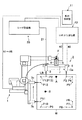
以下、本発明の実施形態について図面を参照して説明する。なお、説明中、記号#nは、ロボット制御装置が各軸のサーボ制御部を介して制御するn番目軸の軸を表わすものとする。図1は、本発明の1つの実施形態に係るレーザ加工装置の要部構成を示す図である。同図において、符号10はシステム全体の制御手段でもあるロボット制御装置で、中央演算処理装置(メインCPU、以下単にCPUと言う。)を備え、同CPUにはRAM及びROMからなるメモリ、教示操作盤11に接続された教示操作盤用インターフェイス、レーザ発振器20に接続されたレーザ装置用入出カインターフェイス、ロボット1の各軸#1〜#6を駆動するサーボモータを制御するサーボ制御部、並びに付加軸#7、#8を駆動するサーボモータを制御するサーボ制御部がバスを介して接続されている。なお、このようなロボット制御装置の内部構成自体は周知のものなので、個別要素の図示並びに詳細な説明は省略する。
Embodiments of the present invention will be described below with reference to the drawings. In the description, the symbol #n represents the n-th axis that is controlled by the robot controller via the servo control unit for each axis. FIG. 1 is a diagram showing a main configuration of a laser processing apparatus according to one embodiment of the present invention. In the figure,
ロボット制御装置10が制御するロボット軸#1〜#6で動作する6軸ロボット1のアーム先端部には、加工ツール2が搭載されている。加工ツール2は、加工ヘッド3を加工ツール2自身の上で移動させるために、少なくとも1つの付加軸で動作する移動機構を有している。本例では、加工ツール2が持つ移動機構は縦移動機構5と横移動機構7で、それぞれ上記した付加軸#7、#8で駆動される。
A
縦移動機構5は、主として加工ヘッド3の高さ方向の位置(加工面との距離)を調節するために使用される機構で、アーム先端部に設定されているメカニカルインターフェイス座標系(原点F)のZ軸方向に沿ってキャリア4を移動させる。縦移動機構5には、図示は省略したが、例えばボールネジとサーボモータを組み合わせた周知の機構を採用することができる。また、横移動機構7は、主として加工線に沿って加工ヘッド3を高速移動させるために使用される機構で、キャリア4と一体的に結合された横移動機構支持ベース6上の設けられている。
The
横移動機構7として、ここではリニアモータ機構が採用され、レーザビームLBの照射口を持つ加工ノズルを備えた加工ヘッド3は、このリニアモータ機構のスライダ(図示省略)上に取付けられている。横移動機構支持ベース6は、キャリア4とともにT字形状を形成して、上記のメカニカルインターフェイス座標系(原点F)のX軸方向(Z軸と直交)に延在している。これに対応して、横移動機構(リニアモータ機構)7が付加軸#8の駆動により動作すると、加工ヘッド3は同メカニカルインターフェイス座標系(原点F)のX軸方向(Z軸と直交)に沿って移動する。なお、横移動機構7として、リニアモータ機構に代えてボールネジとサーボモータを組み合わせた機構を採用することもできる。
Here, a linear motor mechanism is employed as the
レーザ加工が施される被加工物としてのワークは符号Wで示されており、レーザ発振器20から出力されたレーザ光が光ファイバ21を介して加工ヘッド3に供給され、同加工ヘッド3が持つ加工ノズルの先端からワークWの加工箇所に向けて出射されることでレーザ加工が行なわれる。レーザ発振器20の発振オン/オフ、レーザ光出力の調節等の制御は、ロボット制御装置10からの指令に基づいて実行される。
A workpiece as a workpiece to be subjected to laser processing is indicated by a symbol W, and laser light output from the
なお、ロボット1には、上記したメカニカルインターフェイス座標系(原点F)の他に、ベース座標系及びツール座標系が設定されている。ツール座標系の原点は、通常、レーザ加工装置の制御点とされるもので、加工プログラム(後述)では、この制御点が辿るべき加工経路が指定される。ツール座標系の原点(制御点)は、上記のメカニカルインターフェイス座標系の原点Fに対する相対位置で定義されており、そのデータはロボット制御装置10のメモリに予め格納されている。但し、後述するように、本発明では付加軸の移動で点Fに対する加工ヘッド3の位置が変わるので、これを補償するための補正が必要時に行なわれる。図1において、符号Aは加工ヘッドが符号3あるいは3aにある時のツール座標系の原点位置を例示し、符号Bは加工ヘッドが符号3bあるいは3cにある時のツール座標系の原点位置を例示している(ロボット軸#1〜#6が動作すると、ツール座標系はメカニカルインターフェイス座標系と同じ動きをすることに注意)。なお、加工ヘッドが符号3bあるいは3cにある時のロボット1の描示は省略されている。
The
ロボット1に対する教示、付加軸に対する座標設定等は、LCD画面付の教示操作盤11を用いて行わえるようになっている。また、教示操作盤11には、ロボット軸#1〜#6を手動で動作させるジョグ送り機能の他、付加軸#7、#8をの手動軸送りの機能も備わっており、例えば、ロボット1を停止させた状態で、縦移動機構5を動作させて加工ヘッド3とワークWの間の距離を手動調整したり、横移動機構7を動作させて加工ヘッド3をワークWの上方で水平方向に位置調整したりすることができる。
Teaching to the
ロボット制御装置10のメモリには、ロボット1のプログラム、関連設定データ、付加軸の移動命令、レーザ加工命令に対応したプログラムが格納される。ここで、ロボット1がロボット軸#1〜#6に加えて付加軸#7、#8を持っていることに対応して、これら軸の動作指令を出力するためのプログラムは、6軸#1〜#6を制御する第1のプログラムと付加軸#7、#8を制御する第2のプログラムで構成され、ロボット制御装置のソフトウェア処理機能(マルチタスク機能)によって並行的に実行される。
The memory of the
本発明に係るレーザ加工装置においては、加工プログラムの作成を、いわゆるプレイバック方式、オフラインプログラミング方式のいずれによって行なっても良い。前者による場合は、教示操作盤11の上記した手動送り機能を使って、ロボット1(ロボット軸#1〜#6)及び付加軸(#7、#8)を手動で動作させ、加工ヘッド3を順次加工位置に対応付けて教示点として教示することで、加工経路を教示する。そして、教示点間の移動形式(直線移動、円弧移動、各軸移動等の種別)、移動速度、位置決め割合等の条件、レーザ出力条件(レーザ光出力パワー等)を指定するパラメータ、レーザ照射のオン/オフの命令等を追加して加工プログラムとする。
In the laser machining apparatus according to the present invention, the machining program may be created by either a so-called playback method or an offline programming method. In the former case, the robot 1 (
オフラインプログラミングでは、実際のシステムを3次元モデルで模したワークセルをオフラインプログラミングシステム上で定義し、同ワークセル内で教示点、加工経路を定めて、教示点間の移動形式(直線移動、円弧移動、各軸移動等の種別)、移動速度、位置決め割合等の条件、レーザ出力条件(レーザ光出力パワー等)を指定するパラメータ、レーザ照射のオン/オフの命令等を追加して加工プログラムとする。 In offline programming, a work cell simulating an actual system with a three-dimensional model is defined on the offline programming system, teaching points and machining paths are defined in the work cell, and the movement format between the teaching points (linear movement, arc) Type of movement, movement of each axis), conditions such as movement speed, positioning ratio, parameters for specifying laser output conditions (laser beam output power, etc.), laser irradiation on / off command, etc. To do.
ここでは一例として、教示すべき加工経路を図1に示したようなものとする。即ち、加工経路は、P1→P2(レーザ照射オン)、P2→P3(レーザ照射オフ)、P3→P4(レーザ照射オン)、P4→P5(レーザ照射オン)、P5→P6(レーザ照射オフ)、P6→P7(レーザ照射オン)、P7→P8(レーザ照射オン)、P8→P9(レーザ照射オフ)、P9→P10(レーザ照射オン)、P10→P11(レーザ照射オン)、P11→P12(レーザ照射オフ)、P12→P13(レーザ照射オン)となる。つまり、加工経路の始点P1から終点P13(=P1)に至るまでに、加工実行区間(P1→P2、P3→P4、P4→P5、P6→P7、P7→P8、P9→P10、P10→P11、P12→P13)と加工非実行区間(P5→P6、P8→P9、P12→P13)が存在する。また、点P4、P7、P10はコーナ点となっている。 Here, as an example, the machining path to be taught is as shown in FIG. That is, the processing paths are P1 → P2 (laser irradiation on), P2 → P3 (laser irradiation off), P3 → P4 (laser irradiation on), P4 → P5 (laser irradiation on), P5 → P6 (laser irradiation off). , P6 → P7 (laser irradiation on), P7 → P8 (laser irradiation on), P8 → P9 (laser irradiation off), P9 → P10 (laser irradiation on), P10 → P11 (laser irradiation on), P11 → P12 ( Laser irradiation off), P12 → P13 (laser irradiation on). That is, from the start point P1 to the end point P13 (= P1) of the machining path, machining execution sections (P1 → P2, P3 → P4, P4 → P5, P6 → P7, P7 → P8, P9 → P10, P10 → P11). , P12 → P13) and machining non-execution sections (P5 → P6, P8 → P9, P12 → P13). Points P4, P7, and P10 are corner points.
今、加工プログラム作成のためにこのような移動経路を教示するには、例えば次のようにすれば良い。なお、ロボット1が図1に示した姿勢をとり、符号Fで示した位置にメカニカルインターフェイス座標系の原点がある時、ツール先端点(ロボットの制御点)は符号Aで示した位置(P2とP3の中点)にあり、メカニカルインターフェイス座標系上で表現された位置は、Q(X0、Y0、Z0)であるとする。また、「手動送り」は教示操作盤11の操作により行なう。
In order to teach such a movement route for creating a machining program, for example, the following may be performed. When the
(1)付加軸#8を手動送りし、図1に示したロボット姿勢で、図中左端に位置させる(#8値=−z0 とする)。また、付加軸移動に伴うTCP定義データ補正を行なう。補正方法は後述する(以下、同様)。
(1) The
(2)ロボット軸を手動送りし、加工ノズルの先端を位置P1に一致させる。
(3)付加軸#7を手動送りし、加工ノズルの高さを調整し、高さ調整量を記憶する。また、付加軸移動に伴うTCP定義データ補正を行なう。
(4)高さ調整完了時のロボット位置(軸#1〜#6の軸値)と付加軸#7、#8の軸値を記憶する。
(5)ロボット軸を手動送りし、加工ノズルの先端を位置P2に一致させる。
(6)付加軸#7を手動送りし、加工ノズルの高さを調整する。高さ調整量を上記(3)で記憶済みの調整量として、同調整量だけ付加軸#7を移動させても良い(以下における高さ調整も同様である)。また、付加軸移動に伴うTCP定義データ補正を行なう。
(7)高さ調整完了時のロボット位置(軸#1〜#6の軸値)と付加軸#7、#8の軸値を記憶する。また、その時点におけるTCP定義データを記憶する。
(8)付加軸#8を手動送りし、加工ヘッド3を位置P3の直上位置へ移動させる。また、付加軸移動に伴うTCP定義データ補正を行なう。
(9)ロボット軸を手動送りし、加工ノズルの先端を位置P3に一致させる。
(2) The robot axis is manually fed and the tip of the machining nozzle is made to coincide with the position P1.
(3) The
(4) The robot position at the completion of height adjustment (axis values of
(5) The robot axis is manually fed and the tip of the machining nozzle is made to coincide with the position P2.
(6) The
(7) The robot position at the completion of height adjustment (axis values of
(8) The
(9) The robot axis is manually fed and the tip of the machining nozzle is made to coincide with the position P3.
(10)付加軸#7を手動送りし、加工ノズルの高さを調整する。また、付加軸移動に伴うTCP定義データ補正を行なう。
(11)高さ調整完了時のロボット位置(軸#1〜#6の軸値)と付加軸#7、#8の軸値を記憶する。また、その自転におけるTCP定義データを記憶する。
(10) The
(11) The robot position at the completion of height adjustment (axis values of
(12)ロボット軸を手動送りし、加工ノズルの先端を位置P4に一致させる。但し、その時のロボット姿勢を、位置P3における姿勢から、ワークWの上方から見て90度反時計回りに回転させた姿勢とする。これは、区間P5−P6で行なう再度の付加軸による移動に備えてのものである。
(13)付加軸#7を手動送りし、加工ノズルの高さを調整する。また、付加軸移動に伴うTCP定義データ補正を行なう。
(14)高さ調整完了時のロボット位置(TCPの位置、軸#1〜#6の軸値)と付加軸#7、#8の軸値を記憶する。また、その自転におけるTCP定義データを記憶する。
(12) The robot axis is manually fed and the tip of the machining nozzle is made to coincide with the position P4. However, the robot posture at that time is a posture rotated counterclockwise by 90 degrees when viewed from above the workpiece W from the posture at the position P3. This is in preparation for the movement by the additional axis performed again in the sections P5-P6.
(13) Manually feed the
(14) The robot position (TCP position, axis values of
(15)ロボット軸を手動送りし、加工ノズルの先端を位置P5に一致させる。
(16)付加軸#7を手動送りし、加工ノズルの高さを調整する。また、付加軸移動に伴うTCP定義データ補正を行なう。
(17)高さ調整完了時のロボット位置(TCPの位置、軸#1〜#6の軸値)と付加軸#7、#8の軸値を記憶する。また、その自転におけるTCP定義データを記憶する。
(15) The robot axis is manually fed and the tip of the machining nozzle is made to coincide with the position P5.
(16) The
(17) The robot position (TCP position, axis values of
(18)付加軸#8を手動送りし、加工ヘッド3を位置P6の直上位置へ移動させる。また、付加軸移動に伴うTCP定義データ補正を行なう。
(19)付加軸#7を手動送りし、加工ノズルの高さを調整する。
(20)高さ調整完了時のロボット位置(TCPの位置、軸#1〜#6の軸値)と付加軸#7、#8の軸値を記憶する。また、その自転におけるTCP定義データを記憶する。
(18) The
(19) The
(20) The robot position (TCP position, axis values of
(21)ロボット軸を手動送りし、加工ノズルの先端を位置P7に一致させる。但し、その時のロボット姿勢を、位置P6における姿勢から、ワークWの上方から見て90度反時計回りに回転させた姿勢とする。これは、区間P8−P9で行なう再度の付加軸による移動に備えてのものである。
(22)付加軸#7を手動送りし、加工ノズルの高さを調整する。また、付加軸移動に伴うTCP定義データ補正を行なう。
(23)高さ調整完了時のロボット位置(TCPの位置、軸#1〜#6の軸値)と付加軸#7、#8の軸値を記憶する。また、その自転におけるTCP定義データを記憶する。
(21) The robot axis is manually fed and the tip of the machining nozzle is made to coincide with the position P7. However, the robot posture at that time is set to a posture rotated counterclockwise by 90 degrees when viewed from above the workpiece W from the posture at the position P6. This is in preparation for the movement by the additional axis in the section P8-P9 again.
(22) The
(23) The robot position (TCP position, axis values of
(24)ロボット軸を手動送りし、加工ノズルの先端を位置P8に一致させる。
(25)付加軸#7を手動送りし、加工ノズルの高さを調整する。また、付加軸移動に伴うTCP定義データ補正を行なう。
(26)高さ調整完了時のロボット位置(TCPの位置、軸#1〜#6の軸値)と付加軸#7、#8の軸値を記憶する。
(24) The robot axis is manually fed and the tip of the machining nozzle is made to coincide with the position P8.
(25) Manually feed the
(26) The robot position (TCP position, axis values of
(27)付加軸#8を手動送りし、加工ヘッド3を位置P9の直上位置へ移動させる。また、付加軸移動に伴うTCP定義データ補正を行なう。
(28)付加軸#7を手動送りし、加工ノズルの高さを調整する。また、付加軸移動に伴うTCP定義データ補正を行なう。
(29)高さ調整完了時のロボット位置(TCPの位置、軸#1〜#6の軸値)と付加軸#7、#8の軸値を記憶する。
(27) The
(28) The
(29) The robot position (TCP position, axis values of
(30)ロボット軸を手動送りし、加工ノズルの先端を位置P10に一致させる。但し、その時のロボット姿勢を、位置P6における姿勢から、ワークWの上方から見て90度反時計回りに回転させた姿勢とする。これは、区間P11−P12で行なう再度の付加軸による移動に備えてのものである。
(31)付加軸#7を手動送りし、加工ノズルの高さを調整する。
(32)高さ調整完了時のロボット位置(TCPの位置、軸#1〜#6の軸値)と付加軸#7、#8の軸値を記憶する。
(30) The robot axis is manually fed and the tip of the machining nozzle is made to coincide with the position P10. However, the robot posture at that time is set to a posture rotated counterclockwise by 90 degrees when viewed from above the workpiece W from the posture at the position P6. This is in preparation for the movement by the additional axis performed again in the sections P11 to P12.
(31) The
(32) The robot position (TCP position, axis values of
(33)ロボット軸を手動送りし、加工ノズルの先端を位置P11に一致させる。
(34)付加軸#7を手動送りし、加工ノズルの高さを調整する。また、付加軸移動に伴うTCP定義データ補正を行なう。
(35)高さ調整完了時のロボット位置(TCPの位置、軸#1〜#6の軸値)と付加軸#7、#8の軸値を記憶する。
(33) The robot axis is manually fed and the tip of the machining nozzle is made to coincide with the position P11.
(34) The
(35) The robot position (TCP position, axis values of the
(36)付加軸#8を手動送りし、加工ヘッド3を位置P12の直上位置へ移動させる。また、付加軸移動に伴うTCP定義データ補正を行なう。
(37)付加軸#7を手動送りし、加工ノズルの高さを調整する。また、付加軸移動に伴うTCP定義データ補正を行なう。
(38)高さ調整完了時のロボット位置(TCPの位置、軸#1〜#6の軸値)と付加軸#7、#8の軸値を記憶する。
(36) The
(37) The
(38) The robot position (TCP position, axis values of
(39)ロボット軸を手動送りし、加工ノズルの先端を位置P13に一致させる。
(40)付加軸#7を手動送りし、加工ノズルの高さを調整する。また、付加軸移動に伴うTCP定義データ補正を行なう。
(41)高さ調整完了時のロボット位置(TCPの位置、軸#1〜#6の軸値)と付加軸#7、#8の軸値を記憶する。
(39) The robot axis is manually fed, and the tip of the machining nozzle is made to coincide with the position P13.
(40) The
(41) The robot position (TCP position, axis values of the
以上の手順で移動経路を教示したら、教示点間の移動形式(直線移動、円弧移動、各軸移動等の種別)、移動速度、位置決め割合等の条件、レーザ出力条件(レーザ光出力パワー等)を指定するパラメータ、レーザ照射のオン/オフの命令等を追加して加工プログラムとする。ここで、レーザ出力オフで通過する加工非実行区間(P5→P6、P8→P9、P12→P13)では、高い軌道精度は必要としないので、加工実行区間よりも大きな指令速度をものとする。これにより、レーザ加工個所は正確なロボット制御点定義データ(TCP定義データ)により教示が行われ、軌跡精度が必要とされない加工のない個所は高速で移動する加工プログラムが作成される。 Once the movement path is taught in the above procedure, the movement type between the teaching points (types such as linear movement, arc movement, and movement of each axis), conditions such as movement speed and positioning ratio, laser output conditions (laser light output power, etc.) Is added to the parameter for designating, a command for turning on / off the laser irradiation, and the like to obtain a machining program. Here, in the machining non-execution section (P5 → P6, P8 → P9, P12 → P13) that passes when the laser output is off, high trajectory accuracy is not required, and therefore a command speed larger than that in the machining execution section is assumed. As a result, the laser machining location is taught by accurate robot control point definition data (TCP definition data), and a machining program is created that moves at high speed in locations that do not require trajectory accuracy.
加工ヘッド3の付加軸による移動に関して、ロボット制御点定義データ(TCP定義データ)の補正は以下のような計算に基づいて行なわれる。
今、ロボット制御点定義データ(TCP定義データ)の初期値として前出のQ(X0,Y0,Z0)が設定されているとする。また、前述したことから、2つの付加軸が移動すれば、メカニカルインターフェイス座標系ではX軸、Z軸の移動となる。これを△Q1(△X1,△Z1)で表わすと、同付加軸移動にを補償するに必要な補正後のTCP定義データは、Q1(X0+△X1,Y0+△Y1,Z0+△Z1)となる。このように補正・再定義されたTCP定義データが、次のステップでの加工はにおけるTCP定義データとして利用される。
Regarding the movement of the
Now, assume that Q (X0, Y0, Z0) is set as the initial value of the robot control point definition data (TCP definition data). In addition, as described above, if the two additional axes move, the X and Z axes move in the mechanical interface coordinate system. When this is expressed by ΔQ1 (ΔX1, ΔZ1), the corrected TCP definition data necessary to compensate for the additional axis movement is Q1 (X0 + ΔX1, Y0 + ΔY1, Z0 + ΔZ1). . The TCP definition data corrected and redefined in this way is used as TCP definition data in the processing in the next step.
以上にようにして加工プログラムを作成し、ロボット制御装置10のメモリに格納した上で、同プログラムの実行指令を例えば教示操作盤11から入力すると、ロボット制御装置10のプロセッサは図2の処理を開始する。各ステップの要点は下記の通りである。
ステップS1;プログラムの行番号Lを表わす指標を“1”に初期設定(クリア)する。
ステップS2;その時点における行番号指標Lが最終行を表わすものであるか否かチェックし、イエスであれば処理を終了する。ノーであればステップS3へ進む。
When the machining program is created as described above, stored in the memory of the
Step S1: Initially set (clear) the index representing the line number L of the program to “1”.
Step S2: It is checked whether or not the line number index L at that time represents the last line. If yes, the process ends. If no, the process proceeds to step S3.
ステップS3;その時点における行番号指標Lが表わす動作文を読み込む。
ステップS4;レーザ出力をオンしての移動命令(加工実行区間)か、レーザ出力をオフしての移動命令(加工非実行区間)かを判別し、前者であればステップS5へ進み、後者であればステップS6へ進む。
ステップS5;ロボット軸#1〜#6の動作により、レーザ出力オン状態にある加工ヘッド3を移動させる。なお、移動が完了したらレーザオフとして、ステップS8へ進む。 ステップS6;付加軸#7及び/または#8の動作のみ、または、それにロボット軸#1〜#6の動作を組み合わせて、加工ヘッド3を移動させる。なお、レーザは終始オフ状態である。
ステップS7;その時点におけるロボット位置(位置P1〜P13の内の何処にいるか)に対応したTCP定義データ(前述した教示時に記憶)を用いて、ロボット移動に用いるTCP定義データを補正する。
ステップS8;プログラムの行番号Lを表わす指標を1アップして、ステップS2に戻る。以下、ステップS2で最終行の判断が出るまで、上記処理サイクルを繰り返すこで、加工プログラムが実行され、レーザ加工が完了する。この間、付加軸の移動があれば、その都度、TCP定義データが補正され、正しいTCP定義データによりロボットが制御されているので、付加軸の動作により加工経路が教示したものから外れることはない。また、付加軸の動作を組み合わせていることでロボット軸のみで移動する場合に比して、サイクルタイムの短縮が容易となっている。
Step S3: The action sentence represented by the line number index L at that time is read.
Step S4: It is determined whether the movement command (processing execution section) with the laser output turned on or the movement command (processing non-execution section) with the laser output turned off. If the former, the process proceeds to step S5. If there is, the process proceeds to step S6.
Step S5: The machining
Step S7: The TCP definition data used for the robot movement is corrected using the TCP definition data (stored at the time of teaching described above) corresponding to the robot position (where in the positions P1 to P13) at that time.
Step S8: The index indicating the line number L of the program is incremented by 1, and the process returns to step S2. Thereafter, the processing cycle is repeated until the final line is determined in step S2, thereby executing the machining program and completing the laser machining. During this time, if there is a movement of the additional axis, the TCP definition data is corrected each time, and the robot is controlled by the correct TCP definition data, so that the machining path does not deviate from what is taught by the movement of the additional axis. Further, by combining the operations of the additional axes, the cycle time can be easily reduced as compared with the case of moving only by the robot axes.
1 ロボット
2 加工ツール
3、3a、3b、3c 加工ヘッド
4 キャリア
5 縦移動機構
6 横移動機構支持ベース
7 横移動機構(リニアモータ)
10 ロボット制御装置
11 教示操作盤
20 レーザ発振器
21 光ファイバ
LB レーザビーム
W ワーク
DESCRIPTION OF
DESCRIPTION OF
Claims (3)
前記加工ツールは、前記付加軸により移動可能なレーザ加工ヘッドを有し、
前記制御手段は、加工中の前記レーザ加工ヘッドの移動をプログラムに基づいてロボット軸のみの動作により制御する手段と、加工のない区間の前記レーザ加工ヘッドの移動をプログラムに基づいて前記付加軸のみの動作、または前記付加軸と前記ロボット軸の同時動作により制御する手段とを備えている、レーザ加工装置。 Laser processing apparatus comprising: a robot having a robot axis and at least one additional axis; a processing tool mounted on an arm tip of the robot; and a control means for controlling the robot and the processing tool based on software processing In
The processing tool has a laser processing head movable by the additional axis,
The control means controls the movement of the laser machining head during machining by the operation of only the robot axis based on the program, and the movement of the laser machining head in the section without machining only the additional axis based on the program. Or a means for controlling by the simultaneous operation of the additional axis and the robot axis.
Priority Applications (4)
| Application Number | Priority Date | Filing Date | Title |
|---|---|---|---|
| JP2004242648A JP2006055901A (en) | 2004-08-23 | 2004-08-23 | Laser machining apparatus |
| EP05017984A EP1629933A2 (en) | 2004-08-23 | 2005-08-18 | Laser processing apparatus |
| US11/207,830 US20060037951A1 (en) | 2004-08-23 | 2005-08-22 | Laser processing apparatus |
| CNA2005100909763A CN1739904A (en) | 2004-08-23 | 2005-08-22 | Laser processing apparatus |
Applications Claiming Priority (1)
| Application Number | Priority Date | Filing Date | Title |
|---|---|---|---|
| JP2004242648A JP2006055901A (en) | 2004-08-23 | 2004-08-23 | Laser machining apparatus |
Publications (1)
| Publication Number | Publication Date |
|---|---|
| JP2006055901A true JP2006055901A (en) | 2006-03-02 |
Family
ID=35455276
Family Applications (1)
| Application Number | Title | Priority Date | Filing Date |
|---|---|---|---|
| JP2004242648A Pending JP2006055901A (en) | 2004-08-23 | 2004-08-23 | Laser machining apparatus |
Country Status (4)
| Country | Link |
|---|---|
| US (1) | US20060037951A1 (en) |
| EP (1) | EP1629933A2 (en) |
| JP (1) | JP2006055901A (en) |
| CN (1) | CN1739904A (en) |
Cited By (1)
| Publication number | Priority date | Publication date | Assignee | Title |
|---|---|---|---|---|
| US11597093B2 (en) | 2018-10-24 | 2023-03-07 | Fanuc Corporation | Calibration method for laser processing robot |
Families Citing this family (10)
| Publication number | Priority date | Publication date | Assignee | Title |
|---|---|---|---|---|
| JP2009028871A (en) * | 2007-07-30 | 2009-02-12 | Denso Wave Inc | Robot control device |
| DE102008060053B3 (en) * | 2008-12-02 | 2010-03-25 | Kuka Roboter Gmbh | Method and manipulator for laser machining a workpiece |
| US8634950B2 (en) * | 2009-12-14 | 2014-01-21 | Embraer S.A. | Automated positioning and alignment method and system for aircraft structures using robots |
| CN103659465B (en) * | 2012-09-21 | 2016-03-09 | 财团法人工业技术研究院 | compensation control method for multi-axis machine |
| JP5905545B2 (en) * | 2014-08-26 | 2016-04-20 | ファナック株式会社 | I / O control system |
| JP6717736B2 (en) * | 2016-11-28 | 2020-07-01 | ファナック株式会社 | Laser processing system |
| DE102017121526A1 (en) * | 2017-09-15 | 2019-03-21 | Rollomatic S.A. | Device for aligning and positioning a workpiece relative to a laser beam of a laser processing machine |
| CN108856169A (en) * | 2018-05-03 | 2018-11-23 | 黄云 | A kind of the laser automatic rust removing device and derusting method of igneous rock cracks |
| CN112317956A (en) * | 2020-09-30 | 2021-02-05 | 成都飞机工业(集团)有限责任公司 | Movable field laser repairing device |
| CN116944702B (en) * | 2023-09-19 | 2024-04-16 | 南通科美自动化科技有限公司 | In-situ laser cutting method |
Family Cites Families (5)
| Publication number | Priority date | Publication date | Assignee | Title |
|---|---|---|---|---|
| JP2643683B2 (en) * | 1990-10-29 | 1997-08-20 | 三菱電機株式会社 | Robot control method |
| FR2674780B1 (en) * | 1991-04-08 | 1995-06-23 | Aro | TOOL CONTROL SYSTEM COMPRISING A CLAMP CONTROLLED BY AN AUTOMATIC POSITIONING SYSTEM. |
| JPH06179092A (en) * | 1992-12-14 | 1994-06-28 | Fanuc Ltd | Method and device for laser beam machining by laser robot |
| US6284999B1 (en) * | 1999-07-23 | 2001-09-04 | Lillbacka Jetair Oy | Laser cutting system |
| DE20216636U1 (en) * | 2002-10-28 | 2004-03-11 | Kuka Schweissanlagen Gmbh | processing plant |
-
2004
- 2004-08-23 JP JP2004242648A patent/JP2006055901A/en active Pending
-
2005
- 2005-08-18 EP EP05017984A patent/EP1629933A2/en not_active Withdrawn
- 2005-08-22 CN CNA2005100909763A patent/CN1739904A/en active Pending
- 2005-08-22 US US11/207,830 patent/US20060037951A1/en not_active Abandoned
Cited By (1)
| Publication number | Priority date | Publication date | Assignee | Title |
|---|---|---|---|---|
| US11597093B2 (en) | 2018-10-24 | 2023-03-07 | Fanuc Corporation | Calibration method for laser processing robot |
Also Published As
| Publication number | Publication date |
|---|---|
| US20060037951A1 (en) | 2006-02-23 |
| EP1629933A2 (en) | 2006-03-01 |
| CN1739904A (en) | 2006-03-01 |
Similar Documents
| Publication | Publication Date | Title |
|---|---|---|
| EP1629933A2 (en) | Laser processing apparatus | |
| JP4406034B2 (en) | Numerical control device for controlling a 5-axis machine | |
| EP1661657B1 (en) | Laser processing robot system with a scanning head and a rapid movable support mechanism ; Method for controlling the same | |
| JP4351281B2 (en) | Numerical control device for controlling a 5-axis machine | |
| JP6325646B1 (en) | Laser processing robot system for performing laser processing using robot and control method of laser processing robot | |
| JP4917252B2 (en) | Arc welding equipment | |
| KR20180103999A (en) | Welding apparatus and control method of welding apparatus | |
| JP2011067858A (en) | Machining controller, laser beam machining device, and laser beam machining system | |
| JP2006099260A (en) | Robot program creating device | |
| JP2019104097A (en) | Robot system | |
| JP4625112B2 (en) | Robot program creation device | |
| JP4805123B2 (en) | Torch groove angle control method and torch groove angle control device | |
| WO1988006938A1 (en) | Laser oscillation controller | |
| JP7553587B2 (en) | Laser processing system and control method | |
| JP4277747B2 (en) | Laser processing equipment | |
| JPH0818130B2 (en) | Weaving welding control method | |
| JP5143661B2 (en) | NC lathe control method and control device | |
| JP7553588B2 (en) | Laser processing system and control method | |
| JP5005366B2 (en) | Robot controller | |
| JP2007029995A (en) | Programming device for arc welding | |
| JP2003308115A (en) | Numerically controlled machine tool | |
| JP2002006913A (en) | Numerical control equipment of machine tool and method for groove machining | |
| JPH0761557B2 (en) | Laser processing equipment | |
| WO2022080448A1 (en) | Laser processing system and control method | |
| JPH0557642A (en) | Industrial robot control device |
Legal Events
| Date | Code | Title | Description |
|---|---|---|---|
| A977 | Report on retrieval |
Free format text: JAPANESE INTERMEDIATE CODE: A971007 Effective date: 20080121 |
|
| A131 | Notification of reasons for refusal |
Free format text: JAPANESE INTERMEDIATE CODE: A131 Effective date: 20080212 |
|
| A521 | Written amendment |
Free format text: JAPANESE INTERMEDIATE CODE: A523 Effective date: 20080414 |
|
| A02 | Decision of refusal |
Free format text: JAPANESE INTERMEDIATE CODE: A02 Effective date: 20080930 |