EP0483720B1 - Dispositif de fixation dans l'espace - Google Patents
Dispositif de fixation dans l'espace Download PDFInfo
- Publication number
- EP0483720B1 EP0483720B1 EP91118338A EP91118338A EP0483720B1 EP 0483720 B1 EP0483720 B1 EP 0483720B1 EP 91118338 A EP91118338 A EP 91118338A EP 91118338 A EP91118338 A EP 91118338A EP 0483720 B1 EP0483720 B1 EP 0483720B1
- Authority
- EP
- European Patent Office
- Prior art keywords
- fixing
- abutment
- screw
- elements
- arms
- Prior art date
- Legal status (The legal status is an assumption and is not a legal conclusion. Google has not performed a legal analysis and makes no representation as to the accuracy of the status listed.)
- Expired - Lifetime
Links
- 230000006870 function Effects 0.000 description 2
- 230000001154 acute effect Effects 0.000 description 1
- 230000007547 defect Effects 0.000 description 1
- 238000003754 machining Methods 0.000 description 1
- 239000002184 metal Substances 0.000 description 1
Images


Classifications
-
- B—PERFORMING OPERATIONS; TRANSPORTING
- B23—MACHINE TOOLS; METAL-WORKING NOT OTHERWISE PROVIDED FOR
- B23Q—DETAILS, COMPONENTS, OR ACCESSORIES FOR MACHINE TOOLS, e.g. ARRANGEMENTS FOR COPYING OR CONTROLLING; MACHINE TOOLS IN GENERAL CHARACTERISED BY THE CONSTRUCTION OF PARTICULAR DETAILS OR COMPONENTS; COMBINATIONS OR ASSOCIATIONS OF METAL-WORKING MACHINES, NOT DIRECTED TO A PARTICULAR RESULT
- B23Q1/00—Members which are comprised in the general build-up of a form of machine, particularly relatively large fixed members
- B23Q1/25—Movable or adjustable work or tool supports
- B23Q1/44—Movable or adjustable work or tool supports using particular mechanisms
- B23Q1/50—Movable or adjustable work or tool supports using particular mechanisms with rotating pairs only, the rotating pairs being the first two elements of the mechanism
- B23Q1/54—Movable or adjustable work or tool supports using particular mechanisms with rotating pairs only, the rotating pairs being the first two elements of the mechanism two rotating pairs only
- B23Q1/545—Movable or adjustable work or tool supports using particular mechanisms with rotating pairs only, the rotating pairs being the first two elements of the mechanism two rotating pairs only comprising spherical surfaces
- B23Q1/5462—Movable or adjustable work or tool supports using particular mechanisms with rotating pairs only, the rotating pairs being the first two elements of the mechanism two rotating pairs only comprising spherical surfaces with one supplementary sliding pair
-
- H—ELECTRICITY
- H01—ELECTRIC ELEMENTS
- H01P—WAVEGUIDES; RESONATORS, LINES, OR OTHER DEVICES OF THE WAVEGUIDE TYPE
- H01P1/00—Auxiliary devices
-
- H—ELECTRICITY
- H01—ELECTRIC ELEMENTS
- H01Q—ANTENNAS, i.e. RADIO AERIALS
- H01Q1/00—Details of, or arrangements associated with, antennas
- H01Q1/12—Supports; Mounting means
- H01Q1/125—Means for positioning
Definitions
- the invention relates to a fixing device in space.
- microwaves it is necessary to carry out a precise positioning of the microwave modules and waveguides of random shapes. It is also important to be able to disassemble these parts, possibly keeping the memory of the optimal position.
- the invention aims to achieve this objective.
- a device for fixing in space a first element to be positioned relative to a second element comprising at least one support piece playing the role of intermediary between two snaps: one to the first element the other to the second; this support piece having the shape of a square comprising two arms forming between them a determined angle; each of these arms being pierced with bores into which may be introduced elements for fixing to one of said elements and for abutment against one of said elements; a fixing element and at least three abutment elements being installed on each of these arms, so as to allow the realization of each of these two hookings.
- this device allows space to be maintained in a rigid position, without mechanical constraint and without particularly precise machining, of microwave elements, waveguides or any other element, with the possibility of preserving the memory of this position in the case of disassembly and reassembly of the same element, or, without retaining the memory of the position, in the case of disassembly of the element in place and its replacement by a new element.
- Figure 1 schematically shows the attachment of an element 10 relative to a frame 11 of any shape by means of the device 12 of the invention.
- the elements 14 and 15 for fixing and abutment, associated with the first arm 16 of said part 13 bear on the frame 11.
- the elements 14 ′ and 15 ′ for fixing and abutment associated with the second arm 17 of said part 13 relate to the element 10 to be positioned.
- the support piece 13 acts as an intermediary between two hooks: one to the frame 11, the other to the element 10 to be positioned.
- the support piece 13 shown in Figure 2 has the shape of a square having two arms 16 and 17 forming between them an acute or optu angle ⁇ ; each of these arms 16 and 17 being pierced with bores 34, 35 (34 ′, 35 ′) into which the fixing elements 14 (14 ′) and the stopper 15 (15 ′) can be introduced. But it can have any other shape such that it has two flat parts, forming between them this angle ⁇ , on which are located these different elements 14 and 15 (14 'and 15 ′).
- the contact points between the three associated abutment elements 15 or (15 ′) and the frame 11 (or the element 10 to be positioned) make it possible, in fact, to define one and only one adjustment plane.
- the fixing elements 14 and 14 ′ are placed and adjusted successively by traction, and the abutment elements 15 and 15 ′ by thrust.
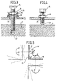
- the fastening elements 14 and 14 ′ are screws bearing on two spherical washers 18 and 19 of one (18) concave and the other (19) convex with a lock nut 20.
- Such a screw can therefore pivot around a point 0 located on its axis of symmetry, the first washer 18 then sliding in the second washer 19 according to a movement 21 as shown in Figures 3 and 5.
- Such a screw 14 or 14 ′ is therefore introduced in a corresponding thread 22 or 22 ′ produced in the frame 11 or in the element 10.
- the abutment elements 15 and 15 ′ are screws with spherical bits 23 or with ball ends, provided with a lock nut 24.
- these different screws are installed on the two arms 16 and 17 of the two support parts 13, which are made of folded or welded sheet metal.
- the fixing screws 14 and 14 ′ make it possible to maintain without constraint, a constant space on the one hand between the first support element 13 and the frame 11, and on the other hand between the second support element and item 10.
- the stop screws 15 and 15 ′ accept parallelism defects and variations in the shapes between the element to be maintained and the support.
- the "position memory” function is carried out by these stop screws 15 and 15 ′ and their respective locknuts; it is essential to reassemble the element which has just been dismantled without any new adjustment. This function can be canceled by loosening the locknuts of the stop screws 15 and 15 'to allow, for example, the positioning of a new element 10 of different shape.
- FIG. 6 gives an exemplary embodiment of the device of the invention in the microwave domain.
- the element 10 to be positioned is then a waveguide 30 of rectangular section, provided with a fixing flange 31.
- the device of the invention is then very advantageous because the internal dimensions of such a microwave waveguide are very precise as regards the internal walls. It is not the same with regard to the external walls.
Landscapes
- Engineering & Computer Science (AREA)
- Mechanical Engineering (AREA)
- Connection Of Plates (AREA)
- Mutual Connection Of Rods And Tubes (AREA)
- Harvester Elements (AREA)
- Agricultural Machines (AREA)
- Microwave Tubes (AREA)
- Waveguide Connection Structure (AREA)
- Clamps And Clips (AREA)
Description
- L'invention concerne in dispositif de fixation dans l'espace.
- Il est connu de relier deux éléments par l'intermédiaire d'une pièce intermédiaire et de plusieurs vis, comme décrit dans la demande de brevet européen EP-A-0274084 cette pièce intermédiaire pouvant avoir une forme d'équerre, comme dans le brevet US-A-2 667 318.
- Il est également connu de fixer une pièce dans une position voulue sur une autre pièce à l'aide d'un boulon de serrage et de quatre vis de réglage par butée comme décrit dans le brevet FR-A-492 526.
- Dans le cas particulier des hyperfréquences il est nécessaire de réaliser un positionnement précis des modules hyperfréquences et des guides d'ondes de formes aléatoires. Il est important également de pouvoir démonter ces pièces en gardant éventuellement la mémoire de la position optimale.
- L'invention a pour but de réaliser cet objectif.
- Elle propose, à cet effet, un dispositif de fixation dans l'espace d'un premier élément à positionner par rapport à un second élément, comprenant au moins une pièce support jouant le rôle d'intermédiaire entre deux accrochages : l'un au premier élément l'autre au second; cette pièce support ayant la forme d'une équerre comportant deux bras formant entre eux un angle déterminé; chacun de ces bras étant percé d'alésages dans lesquels peuvent être introduits des éléments de fixation à l'un desdits éléments et de butée contre l'un desdits éléments; un élément de fixation et au moins trois éléments de butée étant implantés sur chacun de ces bras, de manière à permettre la réalisation de chacun de ces deux accrochages.
- Avantageusement ce dispositif permet de réaliser dans l'espace le maintien en position rigide, sans contrainte mécanique et sans usinage particulièrement précis, d'éléments hyperfréquences, de guides d'ondes ou de tout autres éléments, avec la possibilité de conserver la mémoire de cette position dans le cas de démontage et remontage du même élément, ou, sans conserver la mémoire de la position, dans le cas de démontage de l'élément en place et son remplacement par un nouvel élément.
- Les caractéristiques et avantages de l'invention ressortiront de la description qui va suivre, à titre d'exemple non limitatif, en référence aux dessins annexés sur lesquels :
- la figure 1 illustre schématiquement le dispositif de fixation selon l'invention;
- les figures 2 à 5 illustrent différents aspects du dispositif de fixation selon l'invention;
- la figure 6 illustre un exemple de réalisation du dispositif selon l'invention.
- La figure 1 représente schématiquement la fixation d'un élément 10 par rapport à un bâti 11 de forme quelconque au moyen du dispositif 12 de l'invention.
- Ce dispositif 12 comprend au moins une pièce support 13 rigide, ici au nombre de deux, ayant la forme d'une équerre, et comportant donc deux bras 16 et 17 tels que représentés sur la figure 1, sur laquelle sont implantées, respectivement sur chaque face de ladite pièce;
- un élément 14 (14′) de fixation;
- trois éléments 15 (15′) de butée;
- Les éléments 14 et 15 de fixation et de butée, associés au premier bras 16 de ladite pièce 13 portent sur le bâti 11. Les éléments 14′ et 15′ de fixation et de butée associés au second bras 17 de ladite pièce 13 portent sur l'élément 10 à positionner.
- Ainsi la pièce support 13 joue le rôle d'intermédiaire entre deux accrochages : l'un au bâti 11, l'autre à l'élément 10 à positionner.
- La pièce support 13 représentée sur la figure 2 a la forme d'une équerre comportant deux bras 16 et 17 formant entre eux un angle ϑ aigu ou optu; chacun de ces bras 16 et 17 étant percé d'alésages 34, 35 (34′, 35′) dans lesquels peuvent être introduits les éléments de fixation 14 (14′) et de butée 15(15′). Mais elle peut avoir tout autre forme telle qu'elle présente deux parties planes, formant entre elles cet angle ϑ, sur lesquelles soient implantés ces différents éléments 14 et 15 (14' et 15′).
- Les points de contact entre les trois éléments de butée associés 15 ou (15′) et le bâti 11 ( ou l'élément 10 à positionner) permettent, en effet, de définir un et un seul plan de réglage.
- Lors du positionnement de l'élément 10 par rapport au bâti 11, on place et on règle successivement les éléments de fixation 14 et 14′ par traction, et les éléments de butée 15 et 15′ par poussée.
- Lors du démontage de l'élément 10, si l'on veut garder une mémoire mécanique de la position obtenue, on doit mémoriser la position des éléments de butée 15 et 15′.
- Dans un exemple de réalisation les éléments de fixation 14 et 14′ sont des vis en appui sur deux rondelles sphériques 18 et 19 d'une (18) concave et l'autre (19) convexe avec un contre-écrou 20. Une telle vis peut donc pivoter autour d'un point 0 situé sur son axe de symétrie, la première rondelle 18 glissant alors dans la seconde rondelle 19 selon un mouvement 21 comme représenté sur les figures 3 et 5. Une telle vis 14 ou 14′ est donc introduite dans un filetage correspondant 22 ou 22′ réalisé dans le bâti 11 ou dans l'élément 10.
- Les éléments de butée 15 et 15′ sont des vis à embouts sphériques 23 ou à embouts à rotules, munies d'un contre-écrou 24.
- Comme représenté sur la figure 1 ces différentes vis sont implantées sur les deux bras 16 et 17 des deux pièces support 13, qui sont réalisés en tôle pliée ou soudée.
- Comme représenté sur la figure 5, les vis de fixation 14 et 14′ permettent de maintenir sans contrainte, un espace constant d'une part entre le premier élément support 13 et le bâti 11, et d'autre part entre le second élément support et l'élément 10.
- Les vis de butée 15 et 15′ acceptent les défauts de parallélisme et les variations des formes entre l'élément à maintenir et le support.
- La fonction "mémoire de la position" est réalisée par ces vis de butée 15 et 15′ et leurs contre-écrous respectifs; elle est indispensable pour remonter l'élément qui vient d'être démonté sans nouveau réglage. Cette fonction peut être annulée par desserrage des contre-écrous des vis de butée 15 et 15′ pour permettre, par exemple, le positionnement d'un nouvel élément 10 de forme différente.
- La figure 6 donne un exemple de réalisation du dispositif de l'invention dans le domaine des hyperfréquences. L'élément 10 à positionner est alors un guide d'onde 30 de section rectangulaire, muni d'une collerette de fixation 31. Le dispositif de l'invention est alors très avantageux car les côtes internes d'un tel guide d'onde hyperfréquence sont très précises en ce qui concerne les parois internes. Il n'en est pas de même en ce qui concerne les parois externes. Lorsque l'on veut démonter ou remplacer un guide d'onde, dans les dispositifs de l'art connu il y a obligation de recommencer les réglages du fait des exigences de précision; ce qui n'est plus le cas avec le dispositif de l'invention.
Claims (9)
- Dispositif de fixation dans l'espace d'un premier élément (10) à positionner par rapport à un second élément (11), comprenant au moins une pièce support (13) jouant le rôle d'intermédiaire entre deux accrochages : l'un au premier élément (10) l'autre au second (11), cette pièce support (13) ayant la forme d'une équerre comportant deux bras (16, 17) formant entre eux un angle déterminé; caractérisé en ce que chacun de ces bras est percé d'alésages (34, 35′; 34′, 35) dans lesquels peuvent être introduits des éléments de fixation (14, 14′) à l'un desdits éléments (10, 11) et de butée (15, 15′) contre l'un desdits éléments (10, 11); un élément de fixation (14, 14′) et au moins trois éléments de butée (15, 15′) étant implantés sur chacun de ces bras, de manière à permettre la réalisation de chacun de ces deux accrochages.
- Dispositif selon la revendication 1, caractérisé en ce que le second élément (11) est un bâti.
- Dispositif selon l'une quelconque des revendications précédentes, caractérisé en ce qu'il comporte deux pièces support (13).
- Dispositif selon l'une quelconque des revendications précédentes, caractérisé en ce que chaque élément de fixation (14, 14′) est une vis qui peut pivoter autour d'un point (0) de son axe de symétrie.
- Dispositif selon la revendication 4, caractérisé en ce que cette vis (14, 14′) comporte une première rondelle sphérique convexe (19) fixée sur la pièce support (13) correspondante, et une seconde rondelle concave (18) dont la partie concave peut glisser sur la partie convexe de la première rondelle (19).
- Dispositif selon la revendication 5, caractérisé en ce que cette vis (14, 14′) comporte un contre-écrou (20).
- Dispositif selon l'une quelconque des revendications précédentes, caractérisé en ce que chaque élément de butée (15, 15′) est une vis dont l'extrémité comporte une portée sphérique (23).
- Dispositif selon la revendication 7, caractérisé en ce que cette vis (15, 15′) comporte un contre-écrou (24).
- Dispositif selon l'une quelconque des revendications précédentes caractérisé en ce que l'élément à positionner est un module hyperfréquence ou un guide d'onde.
Applications Claiming Priority (2)
| Application Number | Priority Date | Filing Date | Title |
|---|---|---|---|
| FR9013451A FR2668654B1 (fr) | 1990-10-30 | 1990-10-30 | Dispositif de fixation dans l'espace. |
| FR9013451 | 1990-10-30 |
Publications (2)
| Publication Number | Publication Date |
|---|---|
| EP0483720A1 EP0483720A1 (fr) | 1992-05-06 |
| EP0483720B1 true EP0483720B1 (fr) | 1995-09-13 |
Family
ID=9401711
Family Applications (1)
| Application Number | Title | Priority Date | Filing Date |
|---|---|---|---|
| EP91118338A Expired - Lifetime EP0483720B1 (fr) | 1990-10-30 | 1991-10-28 | Dispositif de fixation dans l'espace |
Country Status (7)
| Country | Link |
|---|---|
| US (1) | US5195710A (fr) |
| EP (1) | EP0483720B1 (fr) |
| JP (1) | JPH0617807A (fr) |
| CA (1) | CA2054468C (fr) |
| DE (1) | DE69112988T2 (fr) |
| ES (1) | ES2077136T3 (fr) |
| FR (1) | FR2668654B1 (fr) |
Families Citing this family (15)
| Publication number | Priority date | Publication date | Assignee | Title |
|---|---|---|---|---|
| DE4302760A1 (de) * | 1993-02-01 | 1994-08-04 | United Carr Gmbh Trw | Halteelement |
| US5407183A (en) * | 1994-03-01 | 1995-04-18 | Singeltary; James C. | Drywall installation tool |
| US5622485A (en) * | 1995-07-27 | 1997-04-22 | Ametek, Inc. | High performance efficiency dirty air motor/fan system |
| US5732918A (en) * | 1995-07-31 | 1998-03-31 | Steele; Thomas C. | Roof catchboard bracket |
| GB2327863B (en) * | 1997-08-01 | 2001-08-01 | Dsc Telecom Lp | A bracket |
| US6513776B1 (en) * | 1999-05-12 | 2003-02-04 | Mark G. Bissett | Hand tool for securely supporting article during painting |
| US6688798B2 (en) * | 2001-02-27 | 2004-02-10 | Incumed, Inc. | Adjustable locking mount and methods of use |
| US20070162140A1 (en) * | 2001-02-27 | 2007-07-12 | Mcdevitt Dennis M | Method and apparatus for reconstructing a joint |
| US6736852B2 (en) | 2001-02-27 | 2004-05-18 | Incumed, Inc. | Adjustable bone prostheses and related methods |
| US6837009B1 (en) * | 2003-05-12 | 2005-01-04 | Steven A. Roth | Brace for restricting relative movement between a rod and building structure |
| DE202005006152U1 (de) * | 2005-04-15 | 2005-07-07 | Alcamo Ltd. & Co. KG | Verbindungseinrichtung zur Fixierung von flächenförmigen Abtrennungselementen |
| GB2474046B (en) * | 2009-10-02 | 2012-04-04 | Raptorgrip Ltd | A fastening assembly |
| US9561835B2 (en) * | 2012-06-19 | 2017-02-07 | Shimano Inc. | Bicycle brake assembly |
| CN103474150A (zh) * | 2013-06-26 | 2013-12-25 | 石家庄杰泰特动力能源有限公司 | 具有身份标识机构的智能电力电缆 |
| US11445844B2 (en) * | 2020-07-16 | 2022-09-20 | Claus Peter Rodenbostel | Prosthetic locking liner drying hook |
Family Cites Families (13)
| Publication number | Priority date | Publication date | Assignee | Title |
|---|---|---|---|---|
| FR492526A (fr) * | 1923-10-11 | 1919-07-10 | Francois Louis Brodu | Appareil mécanique à position variable et réglage pour le montage des pièces à travailler aux machines-outils |
| US2667318A (en) * | 1950-02-17 | 1954-01-26 | Hugh G Sesler | Mast support |
| US2676778A (en) * | 1950-05-12 | 1954-04-27 | Walter R Pace | Clearance light bracket |
| US2960806A (en) * | 1959-07-13 | 1960-11-22 | Brunswick Corp | Centering device |
| DE1234288B (de) * | 1964-05-11 | 1967-02-16 | Siemens Ag | Vorrichtung zur Halterung von Hohlleitern |
| US3588019A (en) * | 1969-07-07 | 1971-06-28 | Anthony J Cozeck | Bracket for electrical boxes |
| GB1551730A (en) * | 1976-09-29 | 1979-08-30 | Tucker F E | Adjustable wall brackets |
| US4251819A (en) * | 1978-07-24 | 1981-02-17 | Ford Aerospace & Communications Corp. | Variable support apparatus |
| FR2445754A1 (fr) * | 1979-01-08 | 1980-08-01 | Harmand Pierre | Support inclinable pour objet ou piece a usiner |
| US4390172A (en) * | 1980-11-28 | 1983-06-28 | Presco, Inc. | Precise quick-release positioning mechanism |
| US4690359A (en) * | 1986-05-01 | 1987-09-01 | Phillips Randall L | Take-up bracket for flooring adjustment |
| US4896985A (en) * | 1989-05-01 | 1990-01-30 | Simpson Strong-Tie Company, Inc. | Snugging connection and method |
| US5016873A (en) * | 1990-01-16 | 1991-05-21 | Bossa David W | Playswing assembly |
-
1990
- 1990-10-30 FR FR9013451A patent/FR2668654B1/fr not_active Expired - Fee Related
-
1991
- 1991-10-25 US US07/782,471 patent/US5195710A/en not_active Expired - Fee Related
- 1991-10-28 ES ES91118338T patent/ES2077136T3/es not_active Expired - Lifetime
- 1991-10-28 DE DE69112988T patent/DE69112988T2/de not_active Expired - Fee Related
- 1991-10-28 EP EP91118338A patent/EP0483720B1/fr not_active Expired - Lifetime
- 1991-10-29 CA CA002054468A patent/CA2054468C/fr not_active Expired - Fee Related
- 1991-10-30 JP JP3311600A patent/JPH0617807A/ja active Pending
Also Published As
| Publication number | Publication date |
|---|---|
| DE69112988T2 (de) | 1996-02-15 |
| US5195710A (en) | 1993-03-23 |
| CA2054468C (fr) | 1993-12-14 |
| JPH0617807A (ja) | 1994-01-25 |
| ES2077136T3 (es) | 1995-11-16 |
| FR2668654A1 (fr) | 1992-04-30 |
| EP0483720A1 (fr) | 1992-05-06 |
| DE69112988D1 (de) | 1995-10-19 |
| FR2668654B1 (fr) | 1993-04-30 |
| CA2054468A1 (fr) | 1992-05-01 |
Similar Documents
| Publication | Publication Date | Title |
|---|---|---|
| EP0483720B1 (fr) | Dispositif de fixation dans l'espace | |
| FR2734915A1 (fr) | Dispositif pour positionner precisement le sommet du miroir secondaire en decentrement par rapport a celui du miroir primaire d'un telescope et telescope equipe d'un tel dispositif | |
| FR2951408A1 (fr) | Cadre moteur pour moteur electrique de vehicule automobile | |
| FR2851636A1 (fr) | Support articule a debattement lateral pour materiel electrique a haute ou moyenne tension | |
| FR2778009A1 (fr) | Dispositif d'affichage a panneaux plats, notamment a cristaux liquides, et son procede de fabrication | |
| FR2793607A1 (fr) | Dispositif de montage et d'orientation en azimut/elevation d'une antenne | |
| EP3585656B1 (fr) | Dispositif de fixation d'un pare-chocs sur une poutre de pare-chocs de vehicule automobile | |
| FR3018773A1 (fr) | Dispositif de support | |
| EP0126671B1 (fr) | Dispositif de fixation flexible d'une charge utile sur une surface de support, notamment d'un instrument de haute précision sur un engin spatial | |
| FR2701337A1 (fr) | Support universel de têtes pour la réception multiple de satellites sur une seule antenne parabolique fixe. | |
| EP1187703A1 (fr) | Outil de centrage et de serrage | |
| EP3999789B1 (fr) | Tirant pour structure notamment en treillis | |
| EP2713435B1 (fr) | Système de montage d'une antenne sur un support cylindrique | |
| FR2764953A1 (fr) | Dispositif de retenue de broche | |
| EP4074018B1 (fr) | Système video comportant deux capteurs video montés sur une barre | |
| FR2975143A1 (fr) | Dispositif permettant de regler la position angulaire d'un organe, de facon a garantir la liaison de ce dernier avec un support selon un plan de contact d'orientation predeterminee. | |
| EP0743729B1 (fr) | Dispositif de fixation d'un support pour coffret d'appareillage électrique | |
| BE1028105B1 (fr) | Système de connexion articulé pour éléments portants | |
| EP0176397A1 (fr) | Dispositif d'orientation pour un composant optique | |
| EP1369970B1 (fr) | Dispositif de fixation d'un coffret électrique sur une surface de support | |
| FR3056373A1 (fr) | Equipement pour maintenir un composant a l'interieur d'un boitier d'ordinateur | |
| FR2706694A1 (fr) | Châssis pivotant d'armoire électrique et armoire comportant un tel chassis pivotant. | |
| FR3106023A1 (fr) | Armoire, notamment armoire électrique | |
| WO2021115957A1 (fr) | Système vidéo comportant deux capteurs vidéo montés sur une barre mobile en rotation | |
| FR2716013A1 (fr) | Dispositif de blocage à supports concaves. |
Legal Events
| Date | Code | Title | Description |
|---|---|---|---|
| PUAI | Public reference made under article 153(3) epc to a published international application that has entered the european phase |
Free format text: ORIGINAL CODE: 0009012 |
|
| AK | Designated contracting states |
Kind code of ref document: A1 Designated state(s): DE ES FR GB IT NL SE |
|
| 17P | Request for examination filed |
Effective date: 19921102 |
|
| 17Q | First examination report despatched |
Effective date: 19941121 |
|
| GRAA | (expected) grant |
Free format text: ORIGINAL CODE: 0009210 |
|
| AK | Designated contracting states |
Kind code of ref document: B1 Designated state(s): DE ES FR GB IT NL SE |
|
| REF | Corresponds to: |
Ref document number: 69112988 Country of ref document: DE Date of ref document: 19951019 |
|
| ITF | It: translation for a ep patent filed | ||
| REG | Reference to a national code |
Ref country code: ES Ref legal event code: FG2A Ref document number: 2077136 Country of ref document: ES Kind code of ref document: T3 |
|
| GBT | Gb: translation of ep patent filed (gb section 77(6)(a)/1977) |
Effective date: 19951124 |
|
| PLBE | No opposition filed within time limit |
Free format text: ORIGINAL CODE: 0009261 |
|
| STAA | Information on the status of an ep patent application or granted ep patent |
Free format text: STATUS: NO OPPOSITION FILED WITHIN TIME LIMIT |
|
| 26N | No opposition filed | ||
| PGFP | Annual fee paid to national office [announced via postgrant information from national office to epo] |
Ref country code: NL Payment date: 19980914 Year of fee payment: 8 Ref country code: GB Payment date: 19980914 Year of fee payment: 8 |
|
| PGFP | Annual fee paid to national office [announced via postgrant information from national office to epo] |
Ref country code: FR Payment date: 19980916 Year of fee payment: 8 |
|
| PGFP | Annual fee paid to national office [announced via postgrant information from national office to epo] |
Ref country code: SE Payment date: 19980918 Year of fee payment: 8 |
|
| PGFP | Annual fee paid to national office [announced via postgrant information from national office to epo] |
Ref country code: DE Payment date: 19980922 Year of fee payment: 8 |
|
| PGFP | Annual fee paid to national office [announced via postgrant information from national office to epo] |
Ref country code: ES Payment date: 19981020 Year of fee payment: 8 |
|
| PG25 | Lapsed in a contracting state [announced via postgrant information from national office to epo] |
Ref country code: GB Free format text: LAPSE BECAUSE OF NON-PAYMENT OF DUE FEES Effective date: 19991028 |
|
| PG25 | Lapsed in a contracting state [announced via postgrant information from national office to epo] |
Ref country code: ES Free format text: LAPSE BECAUSE OF NON-PAYMENT OF DUE FEES Effective date: 19991029 |
|
| PG25 | Lapsed in a contracting state [announced via postgrant information from national office to epo] |
Ref country code: SE Free format text: THE PATENT HAS BEEN ANNULLED BY A DECISION OF A NATIONAL AUTHORITY Effective date: 19991030 |
|
| PG25 | Lapsed in a contracting state [announced via postgrant information from national office to epo] |
Ref country code: NL Free format text: LAPSE BECAUSE OF NON-PAYMENT OF DUE FEES Effective date: 20000501 |
|
| EUG | Se: european patent has lapsed |
Ref document number: 91118338.2 |
|
| GBPC | Gb: european patent ceased through non-payment of renewal fee |
Effective date: 19991028 |
|
| PG25 | Lapsed in a contracting state [announced via postgrant information from national office to epo] |
Ref country code: FR Free format text: LAPSE BECAUSE OF NON-PAYMENT OF DUE FEES Effective date: 20000630 |
|
| NLV4 | Nl: lapsed or anulled due to non-payment of the annual fee |
Effective date: 20000501 |
|
| PG25 | Lapsed in a contracting state [announced via postgrant information from national office to epo] |
Ref country code: DE Free format text: LAPSE BECAUSE OF NON-PAYMENT OF DUE FEES Effective date: 20000801 |
|
| REG | Reference to a national code |
Ref country code: FR Ref legal event code: ST |
|
| REG | Reference to a national code |
Ref country code: ES Ref legal event code: FD2A Effective date: 20001113 |
|
| PG25 | Lapsed in a contracting state [announced via postgrant information from national office to epo] |
Ref country code: IT Free format text: LAPSE BECAUSE OF NON-PAYMENT OF DUE FEES Effective date: 20051028 |