EP0483328A1 - Remote control device for starting and stopping diesel and petrol engines - Google Patents
Remote control device for starting and stopping diesel and petrol engines Download PDFInfo
- Publication number
- EP0483328A1 EP0483328A1 EP91909715A EP91909715A EP0483328A1 EP 0483328 A1 EP0483328 A1 EP 0483328A1 EP 91909715 A EP91909715 A EP 91909715A EP 91909715 A EP91909715 A EP 91909715A EP 0483328 A1 EP0483328 A1 EP 0483328A1
- Authority
- EP
- European Patent Office
- Prior art keywords
- vehicle
- relay
- starting
- remote control
- housing
- Prior art date
- Legal status (The legal status is an assumption and is not a legal conclusion. Google has not performed a legal analysis and makes no representation as to the accuracy of the status listed.)
- Withdrawn
Links
Images


Classifications
-
- F—MECHANICAL ENGINEERING; LIGHTING; HEATING; WEAPONS; BLASTING
- F02—COMBUSTION ENGINES; HOT-GAS OR COMBUSTION-PRODUCT ENGINE PLANTS
- F02N—STARTING OF COMBUSTION ENGINES; STARTING AIDS FOR SUCH ENGINES, NOT OTHERWISE PROVIDED FOR
- F02N11/00—Starting of engines by means of electric motors
- F02N11/08—Circuits or control means specially adapted for starting of engines
- F02N11/0803—Circuits or control means specially adapted for starting of engines characterised by means for initiating engine start or stop
- F02N11/0807—Remote means
-
- F—MECHANICAL ENGINEERING; LIGHTING; HEATING; WEAPONS; BLASTING
- F02—COMBUSTION ENGINES; HOT-GAS OR COMBUSTION-PRODUCT ENGINE PLANTS
- F02N—STARTING OF COMBUSTION ENGINES; STARTING AIDS FOR SUCH ENGINES, NOT OTHERWISE PROVIDED FOR
- F02N11/00—Starting of engines by means of electric motors
- F02N11/08—Circuits or control means specially adapted for starting of engines
-
- F—MECHANICAL ENGINEERING; LIGHTING; HEATING; WEAPONS; BLASTING
- F02—COMBUSTION ENGINES; HOT-GAS OR COMBUSTION-PRODUCT ENGINE PLANTS
- F02N—STARTING OF COMBUSTION ENGINES; STARTING AIDS FOR SUCH ENGINES, NOT OTHERWISE PROVIDED FOR
- F02N11/00—Starting of engines by means of electric motors
- F02N11/10—Safety devices
- F02N11/101—Safety devices for preventing engine starter actuation or engagement
-
- F—MECHANICAL ENGINEERING; LIGHTING; HEATING; WEAPONS; BLASTING
- F02—COMBUSTION ENGINES; HOT-GAS OR COMBUSTION-PRODUCT ENGINE PLANTS
- F02B—INTERNAL-COMBUSTION PISTON ENGINES; COMBUSTION ENGINES IN GENERAL
- F02B1/00—Engines characterised by fuel-air mixture compression
- F02B1/02—Engines characterised by fuel-air mixture compression with positive ignition
- F02B1/04—Engines characterised by fuel-air mixture compression with positive ignition with fuel-air mixture admission into cylinder
-
- F—MECHANICAL ENGINEERING; LIGHTING; HEATING; WEAPONS; BLASTING
- F02—COMBUSTION ENGINES; HOT-GAS OR COMBUSTION-PRODUCT ENGINE PLANTS
- F02B—INTERNAL-COMBUSTION PISTON ENGINES; COMBUSTION ENGINES IN GENERAL
- F02B3/00—Engines characterised by air compression and subsequent fuel addition
- F02B3/06—Engines characterised by air compression and subsequent fuel addition with compression ignition
Definitions
- the present invention relates to a remote control device for starting and stopping diesel and petrol engines which can be connected to any alarm apparatus with remote control and which, in addition to starting and stopping the engine of the vehicle, makes it possible to block the starting motor and to cut off the ignition while the alarm is activated, thus achieving an antitheft effect which is added to the already existing alarm effect.
- the present invention represents an additional development over already known automatic alarm and vehicle-door-opening systems, introducing the new function of starting and stopping the engine of the vehicle and even moving the latter a few centimetres.
- Spanish Utility Models Nos. 271,768, 287,752 and 8,803,607 may be mentioned as more representative examples of the prior art on which the invention is based. Nevertheless, those systems included in the prior art mentioned are of more limited scope than that of the present invention, since they have not provided a solution to the technical problems posed by the remote controlled starting and stopping of the engine of a vehicle.
- the invention has developed a remote control device for starting and stopping diesel and petrol engines which is compatible with alarm and antitheft systems existing on the market.
- This device comprises a housing inside which are mounted the various electrical and electronic components of the operating system and which interacts with an alarm unit installed in the vehicle and activated by means of a corresponding remote control. Inside the housing is installed a printed circuit plate from which emerge, via one end, several terminal pins provided for the connection of the device to electrical lines which go to the ignition of the engine, to the alarm unit and to other operational parts, such as heating, fan or air conditioning.
- the plate mentioned has mounted on it, as essential components of the device of the invention, a number of timers which can be adjusted from outside via individual orifices provided on one side of said housing and intended for regulating the time of action of the starting motor of the vehicle and the time delay before starting diesel and injection engines, a relay connected to the system, designed in order to act only if the handbrake is actuated and the gear change lever is in the neutral position, a pair of ignition relays, a relay intended to deenergise the circuit when stopping the vehicle or engaging a gear, a relay, which is normally open, for impeding actuation of the starting motor if the contact key is in the running position, and a relay for regulating the activation time of the starting motor.
- a number of timers which can be adjusted from outside via individual orifices provided on one side of said housing and intended for regulating the time of action of the starting motor of the vehicle and the time delay before starting diesel and injection engines
- a relay connected to the system, designed in order to act only
- the housing of the device of the invention may have any suitable shape, but will preferably consist of a prismatic body of rectangular cross section.
- a switch associated with the gear change lever which preferably consists of a mercury switch but which could also be any other switch suitable for performing a similar function. The closed or open position of this switch will depend, respectively, on said lever being in the neutral position or with a gear engaged.
- the device of the invention is designed so that it can be fitted to alarms activated both by infrared controls and by radiofrequency controls. Said device may also be activated by the pulses received from the locking unit, which are controlled by means of infrared controls incorporated during production in certain vehicles.
- the device of the invention comprises a housing 1 inside which is mounted a printed circuit plate 2 from which start, via one end, several terminal pins 3 provided for connection to electrical lines which go to the ignition 4 of the engine, to the alarm unit 5 and to other operational parts, such as the heating, the fan or the air conditioning.
- Said plate 2 carries an integrated module 6 which, together with a potentiometer 6', constitutes the timer for the activation of the starting motor.
- the plate 2 includes another timer 7 with its corresponding potentiometer 7' for regulating the time delay before the engine starts. Both potentiometers 6' and 7' may be adjusted from outside via individual orifices 8 and 9 provided on a side of the housing 1.
- the plate 2 also includes a relay 13 connected to the system, which is designed to act only if the handbrake of the vehicle is actuated and the gear change lever is in the neutral position.
- a pair of ignition relays 11 and 12 make it possible for starting of the engine to take place only if they are activated, and a relay 10 serves to deenergise the circuit of the device of the invention when stopping the vehicle or engaging a gear.
- the plate 2 also carries a normally open relay 14 which is intended to impede actuation of the starting motor of the vehicle if the contact key is in the running position, there also being on the plate 2 a relay 15 which has the task of activating the starting motor of the vehicle.
- the device of the invention requires an electrical supply of 10 to 16 volts, with a load on the contacts of 30 A. Consumption at rest is zero (0 A) and the operating temperature may oscillate between -30°C and +70°C.
- the device of the invention may be mounted in any model of vehicle which is equipped with a remote control alarm system, and the fitting operations present no particular problem. During these operations, the negative pole of the battery must be disconnected and this will have to be reconnected after completing the fitting of the device at any suitable point inside the interior of the vehicle, for example under the dashboard. As illustrated in Figures 2 to 6, fitting is performed in two parts, the first of which corresponds to the connection of the power stage ( Figure 2), which must be effected with 26-mm cable, whilst the second part relates to the connection with the alarm unit 5 (Figures 3 to 6), which can be effected with 10- or 16-mm cable.
- connection illustrated in a diagrammatic manner in Figure 2 shows how the electrical lines emerging from the first five pins 3 of the housing 1 go to the lines which emerge from the ignition lock 4 of the vehicle as well as to the starting motor 16, a protection fuse 17 and an auxiliary 30-A relay 18 being inserted in the circuit.
- the installation of this auxiliary relay 18 is advisable since it contributes to facilitating the actuation of the starting motor 16.
- connection illustrated in diagrammatic form in Figure 3 is provided for vehicles equipped with centralised locks, in which the alarm unit 5 sends negative pulses to the small unit of the locks, the pulses arriving at the doors via the lines denoted 19 and 20.
- the alarm unit 5 sends negative pulses to the small unit of the locks, the pulses arriving at the doors via the lines denoted 19 and 20.
- a switch 21 inserted in the lines emerging from the terminal pins 3 which makes it possible to place the device of the invention out of service, as a result of which the vehicle will operate the same as any other vehicle equipped with a normal alarm.
- a switch 22 at the gear change lever and another switch 23 for the handbrake there is a switch 22 at the gear change lever and another switch 23 for the handbrake.
- the switch 22 may be a mercury switch or any other suitable type of switch and its closed or open position depends, respectively, on said lever being in the neutral position or with a gear engaged.
- connection layout illustrated in Figure 4 is intended for vehicles equipped with centralised locks, in which the alarm unit 5 sends positive pulses to the small unit of the locks, the reference numbers in this figure having the same meanings as in Figure 3.
- connection layout in Figure 5 is intended for vehicles which are not equipped with centralised locks and which are provided with electromagnetic or motor-operated locks, the alarm unit 5 of these vehicles delivering an electrical supply of one sign for opening the doors, and the same supply, but reversed, for locking the doors.
- the reference numbers included in this figure have the same meanings as in Figures 3 and 4.
- connection layout in Figure 6 is suitable for vehicles with electropneumatic door activation, such as is employed in vehicles of the Mercedes, Audi, etc. type.
- This layout corresponds basically to that of Figure 3, except that, herein, the lines 19 and 20 are connected to the locking unit or module 24 of the alarm which, in turn, is connected to the compressor/decompressor 25 of the vehicle.
- connection of the layouts in Figures 2 to 6 will have to be effected in accordance with the pulses supplied by the alarm to the actuation module of the centralised system.
- Activation of the device of the invention may be based both on radio pulses and on infrared waves.
- connection of the device of the invention is completed with a green light-emitting diode (LED) which indicates the neutral position of the gear change lever and which at the same time provides information on the satisfactory operating of the change sensor.
- the red cable of this diode will be connected to a constant positive and the black to the output of the abovementioned sensor.
- the device according to the invention makes it possible to obtain, in a simple and economical manner, the various advantages referred to hereinabove, foremost among which is clearly additional security in view of possible terrorist actions.
- another considerable advantage of the device of the invention is that, since its consumption at rest is zero, there is no risk that, as a result of the vehicle being immobilised for several days, it will be possible to produce the discharge of the battery.
- the device of the invention does not have to be combined with any special type of alarm system, it is possible to fit it to any vehicle provided with an alarm without having to incur the additional expense which would be represented by the replacement of the original alarm of the vehicle with another which is compatible with the device of the invention.
Abstract
The remote control device for starting and stopping diesel and petrol engines is comprised of a printed circuit plate (2) with terminal pins (3) connected to operational components of the vehicle, a timer (6) for activating the starting motor, another timer (7) for regulating the time delay before the engine starts, a relay (13) connected to the handbrake engaged and the gear change lever in the neutral position, two ignition relays (11,12), a relay (10) for deenergizing the circuit when stopping the vehicle or engaging a gear, a relay (14) which impedes actuating the starting motor if the contact key is in the running position, and a relay (15) for activating the starting motor. The invention is useful for improving the security as to vehicle thefts and the detonation of explosive charges connected to the ignition system.
Description
- The present invention relates to a remote control device for starting and stopping diesel and petrol engines which can be connected to any alarm apparatus with remote control and which, in addition to starting and stopping the engine of the vehicle, makes it possible to block the starting motor and to cut off the ignition while the alarm is activated, thus achieving an antitheft effect which is added to the already existing alarm effect.
- Together with remote control starting, it is also possible to warm up the engine in winter and to start the fan or air conditioning in summer so that, upon entering the vehicle, the latter is already at a suitable temperature for the season of the year.
- The present invention represents an additional development over already known automatic alarm and vehicle-door-opening systems, introducing the new function of starting and stopping the engine of the vehicle and even moving the latter a few centimetres. Spanish Utility Models Nos. 271,768, 287,752 and 8,803,607 may be mentioned as more representative examples of the prior art on which the invention is based. Nevertheless, those systems included in the prior art mentioned are of more limited scope than that of the present invention, since they have not provided a solution to the technical problems posed by the remote controlled starting and stopping of the engine of a vehicle. Therefore, there was a need for a device which would permit remote control starting and stopping of diesel and petrol engines and which, in addition to the convenience represented by having the engine already warmed-up upon entering the vehicle, would add to this an additional security factor, particularly in view of possible terrorist actions based on the application of an explosive charge to the ignition and starting system of the vehicle.
- To this end, the invention has developed a remote control device for starting and stopping diesel and petrol engines which is compatible with alarm and antitheft systems existing on the market. This device comprises a housing inside which are mounted the various electrical and electronic components of the operating system and which interacts with an alarm unit installed in the vehicle and activated by means of a corresponding remote control. Inside the housing is installed a printed circuit plate from which emerge, via one end, several terminal pins provided for the connection of the device to electrical lines which go to the ignition of the engine, to the alarm unit and to other operational parts, such as heating, fan or air conditioning. Apart from conventional circuit elements, the plate mentioned has mounted on it, as essential components of the device of the invention, a number of timers which can be adjusted from outside via individual orifices provided on one side of said housing and intended for regulating the time of action of the starting motor of the vehicle and the time delay before starting diesel and injection engines, a relay connected to the system, designed in order to act only if the handbrake is actuated and the gear change lever is in the neutral position, a pair of ignition relays, a relay intended to deenergise the circuit when stopping the vehicle or engaging a gear, a relay, which is normally open, for impeding actuation of the starting motor if the contact key is in the running position, and a relay for regulating the activation time of the starting motor.
- The housing of the device of the invention may have any suitable shape, but will preferably consist of a prismatic body of rectangular cross section.
- Provision is also made in the invention for the vehicle to be able to operate without being connected to the mentioned remote control device for starting and stopping, to which end a switch means for placing the remote control automatic starting function of the engine of the vehicle out of service has been inserted in the circuit which starts from the terminal pins mentioned. In addition, there is a switch associated with the gear change lever, which preferably consists of a mercury switch but which could also be any other switch suitable for performing a similar function. The closed or open position of this switch will depend, respectively, on said lever being in the neutral position or with a gear engaged.
- Likewise, the device of the invention is designed so that it can be fitted to alarms activated both by infrared controls and by radiofrequency controls. Said device may also be activated by the pulses received from the locking unit, which are controlled by means of infrared controls incorporated during production in certain vehicles.
- For a better understanding of the invention, a description thereof is included below, with reference to the appended drawings which reproduce a specific embodiment of the present remote control device for starting and stopping, and in which:
- Figure 1 represents a plan view of the inside of the device of the invention, in which the essential components thereof are illustrated in block form;
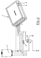
- Figure 2 illustrates diagrammatically the connection of the device of the invention to the power stage of the ignition system of the engine;
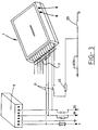
- Figure 3 illustrates diagrammatically the connection of the device of the invention to the alarm unit in vehicles equipped with centralised locks and in those in which the alarm unit sends negative pulses to the small unit of the locks;
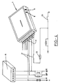
- Figure 4 illustrates diagrammatically the connection of the device of the invention to the alarm unit in vehicles equipped with centralised locks and in those in which the alarm unit sends positive pulses to the small unit of the locks;
- Figure 5 illustrates diagrammatically the connection of the device of the invention to the alarm unit in vehicles not equipped with centralised locks and provided with electromagnetic or motor-operated locks, in which the alarm unit delivers an electrical supply for opening, lock and the same supply, but reversed, for locking;
- Figure 6 illustrates diagrammatically the connection of the device of the invention to the alarm unit in vehicles with electropneumatic door actuation; and
- Figure 7 offers a perspective view of the present embodiment of the device of the invention, in which the lines for connection with operational parts of the vehicle have been eliminated.
- As may be seen particularly in Figure 1, the device of the invention comprises a
housing 1 inside which is mounted a printedcircuit plate 2 from which start, via one end, severalterminal pins 3 provided for connection to electrical lines which go to theignition 4 of the engine, to thealarm unit 5 and to other operational parts, such as the heating, the fan or the air conditioning. Saidplate 2 carries an integratedmodule 6 which, together with a potentiometer 6', constitutes the timer for the activation of the starting motor. Likewise, theplate 2 includes anothertimer 7 with its corresponding potentiometer 7' for regulating the time delay before the engine starts. Both potentiometers 6' and 7' may be adjusted from outside viaindividual orifices housing 1. Theplate 2 also includes arelay 13 connected to the system, which is designed to act only if the handbrake of the vehicle is actuated and the gear change lever is in the neutral position. A pair ofignition relays relay 10 serves to deenergise the circuit of the device of the invention when stopping the vehicle or engaging a gear. Theplate 2 also carries a normallyopen relay 14 which is intended to impede actuation of the starting motor of the vehicle if the contact key is in the running position, there also being on the plate 2 arelay 15 which has the task of activating the starting motor of the vehicle. - The device of the invention requires an electrical supply of 10 to 16 volts, with a load on the contacts of 30 A. Consumption at rest is zero (0 A) and the operating temperature may oscillate between -30°C and +70°C.
- The device of the invention may be mounted in any model of vehicle which is equipped with a remote control alarm system, and the fitting operations present no particular problem. During these operations, the negative pole of the battery must be disconnected and this will have to be reconnected after completing the fitting of the device at any suitable point inside the interior of the vehicle, for example under the dashboard. As illustrated in Figures 2 to 6, fitting is performed in two parts, the first of which corresponds to the connection of the power stage (Figure 2), which must be effected with 26-mm cable, whilst the second part relates to the connection with the alarm unit 5 (Figures 3 to 6), which can be effected with 10- or 16-mm cable.
- The connection illustrated in a diagrammatic manner in Figure 2 shows how the electrical lines emerging from the first five
pins 3 of thehousing 1 go to the lines which emerge from theignition lock 4 of the vehicle as well as to the startingmotor 16, aprotection fuse 17 and an auxiliary 30-A relay 18 being inserted in the circuit. The installation of thisauxiliary relay 18 is advisable since it contributes to facilitating the actuation of the startingmotor 16. - The connection illustrated in diagrammatic form in Figure 3 is provided for vehicles equipped with centralised locks, in which the
alarm unit 5 sends negative pulses to the small unit of the locks, the pulses arriving at the doors via the lines denoted 19 and 20. As may be observed in this figure, there is aswitch 21 inserted in the lines emerging from theterminal pins 3 which makes it possible to place the device of the invention out of service, as a result of which the vehicle will operate the same as any other vehicle equipped with a normal alarm. Likewise, there is aswitch 22 at the gear change lever and anotherswitch 23 for the handbrake. Theswitch 22 may be a mercury switch or any other suitable type of switch and its closed or open position depends, respectively, on said lever being in the neutral position or with a gear engaged. - The connection layout illustrated in Figure 4 is intended for vehicles equipped with centralised locks, in which the
alarm unit 5 sends positive pulses to the small unit of the locks, the reference numbers in this figure having the same meanings as in Figure 3. - The connection layout in Figure 5 is intended for vehicles which are not equipped with centralised locks and which are provided with electromagnetic or motor-operated locks, the
alarm unit 5 of these vehicles delivering an electrical supply of one sign for opening the doors, and the same supply, but reversed, for locking the doors. The reference numbers included in this figure have the same meanings as in Figures 3 and 4. - The connection layout in Figure 6 is suitable for vehicles with electropneumatic door activation, such as is employed in vehicles of the Mercedes, Audi, etc. type. This layout corresponds basically to that of Figure 3, except that, herein, the
lines module 24 of the alarm which, in turn, is connected to the compressor/decompressor 25 of the vehicle. - The connections of the layouts in Figures 2 to 6 will have to be effected in accordance with the pulses supplied by the alarm to the actuation module of the centralised system. Activation of the device of the invention may be based both on radio pulses and on infrared waves.
- Finally, the connection of the device of the invention is completed with a green light-emitting diode (LED) which indicates the neutral position of the gear change lever and which at the same time provides information on the satisfactory operating of the change sensor. The red cable of this diode will be connected to a constant positive and the black to the output of the abovementioned sensor.
- The device according to the invention makes it possible to obtain, in a simple and economical manner, the various advantages referred to hereinabove, foremost among which is clearly additional security in view of possible terrorist actions. In addition, another considerable advantage of the device of the invention is that, since its consumption at rest is zero, there is no risk that, as a result of the vehicle being immobilised for several days, it will be possible to produce the discharge of the battery.
- Moreover, given that the device of the invention does not have to be combined with any special type of alarm system, it is possible to fit it to any vehicle provided with an alarm without having to incur the additional expense which would be represented by the replacement of the original alarm of the vehicle with another which is compatible with the device of the invention.
- The aforesaid sets out what is regarded as the preferred embodiment of the device of the invention. Nevertheless, as will be obvious to experts in the field, it would be possible to modify or substitute some of the operational components of said device with other equivalent components without thereby adversely affecting the basic characteristics and structure of the device. Consequently, it is claimed that the invention is limited only by the contents of the following claims.
Claims (5)
- Remote control device for starting and stopping diesel and petrol engines, which comprises a housing inside which are arranged the various electrical and electronic components of the operating system and which interacts with an alarm unit installed in the vehicle and activated by means of a corresponding remote control, characterised in that it includes, inside said housing (1), a printed circuit plate (2) from which emerge, via one end, several terminal pins (3) provided for connection to electrical lines which go to the ignition of the engine, to the alarm unit and to other operational parts, such as heating, fan or air conditioning, the following components being mounted on said plate (2): an integrated electronic circuit (6) which, together with a potentiometer (6') which can be adjusted from outside via an orifice (8) made in a side of said housing (1), constitutes the timer for the activation of the starting motor; another timer (7) with its corresponding potentiometer (7') for regulating the time delay before the engine starts, it being possible for the potentiometer (7') to be adjusted from outside via an orifice (9) made in the same side of said housing (1) as the orifice (8) previously mentioned; a relay (13) connected to the system, designed in order to act only if the handbrake of the vehicle is actuated and the gear change lever is in the neutral position; a pair of ignition relays (11, 12); a relay (10) intended to deenergise the circuit when stopping the vehicle or engaging a gear; a relay (14), which is normally open, intended to impede actuation of the starting motor of the vehicle if the contact key is in the running position; and a relay (15) for activating the starting motor.
- A device according to Claim 1, characterised in that the housing (1) consists of a prismatic body of rectangular cross section.
- A device according to either of Claims 1 or 2, characterised in that, in the circuit which starts from the terminal pins (3), is inserted a switch means (21) for placing the remote control automatic starting function of the engine of the vehicle out of service, another switch (22) being fitted at the gear change lever.
- A device according to Claim 3, characterised in that the switch (22) is a mercury switch or the like, whose closed or open position depends, respectively, on the gear change lever being in the neutral position or with a gear engaged.
- A device according to any of Claims 1 to 4, characterised in that it is structured so that it can be fitted to alarms activated both by infrared controls and by radiofrequency controls, and it can also be activated by the pulses received from the locking unit, which are controlled by means of infrared controls incorporated during production in certain vehicles.
Applications Claiming Priority (2)
| Application Number | Priority Date | Filing Date | Title |
|---|---|---|---|
| ES9001405A ES2025388A6 (en) | 1990-05-21 | 1990-05-21 | Remote control device for starting and stopping diesel and petrol engines. |
| ES9001405 | 1990-05-21 |
Publications (1)
| Publication Number | Publication Date |
|---|---|
| EP0483328A1 true EP0483328A1 (en) | 1992-05-06 |
Family
ID=8267389
Family Applications (1)
| Application Number | Title | Priority Date | Filing Date |
|---|---|---|---|
| EP91909715A Withdrawn EP0483328A1 (en) | 1990-05-21 | 1991-05-20 | Remote control device for starting and stopping diesel and petrol engines |
Country Status (6)
| Country | Link |
|---|---|
| EP (1) | EP0483328A1 (en) |
| JP (1) | JPH05501291A (en) |
| KR (1) | KR920704005A (en) |
| CA (1) | CA2064000A1 (en) |
| ES (1) | ES2025388A6 (en) |
| WO (1) | WO1991018201A1 (en) |
Family Cites Families (3)
| Publication number | Priority date | Publication date | Assignee | Title |
|---|---|---|---|---|
| EP0139807A1 (en) * | 1983-05-09 | 1985-05-08 | TECKEL S.r.l. | Device for timed or radio control of warm-up and ignition of the engine of a motor vehicle |
| US4674454A (en) * | 1985-08-22 | 1987-06-23 | Donald Phairr | Remote control engine starter |
| CA1252545A (en) * | 1987-12-09 | 1989-04-11 | Joshua K. Tin | Two way remote controller |
-
1990
- 1990-05-21 ES ES9001405A patent/ES2025388A6/en not_active Expired - Fee Related
-
1991
- 1991-05-20 EP EP91909715A patent/EP0483328A1/en not_active Withdrawn
- 1991-05-20 JP JP3509196A patent/JPH05501291A/en active Pending
- 1991-05-20 CA CA002064000A patent/CA2064000A1/en not_active Abandoned
- 1991-05-20 KR KR1019920700131A patent/KR920704005A/en not_active Application Discontinuation
- 1991-05-20 WO PCT/ES1991/000031 patent/WO1991018201A1/en not_active Application Discontinuation
Non-Patent Citations (1)
| Title |
|---|
| See references of WO9118201A1 * |
Also Published As
| Publication number | Publication date |
|---|---|
| WO1991018201A1 (en) | 1991-11-28 |
| CA2064000A1 (en) | 1991-11-22 |
| KR920704005A (en) | 1992-12-18 |
| JPH05501291A (en) | 1993-03-11 |
| ES2025388A6 (en) | 1992-03-16 |
Similar Documents
| Publication | Publication Date | Title |
|---|---|---|
| US5449957A (en) | Self-contained anti-theft device for motor vehicles | |
| US4227588A (en) | Automatic vehicle starting apparatus | |
| CA1063668A (en) | Interior lighting delay circuit | |
| EP0648380B1 (en) | Security batteries for automotive vehicles | |
| US4063610A (en) | Vehicle theft-prevention system | |
| US4110734A (en) | Anti-theft starting system | |
| US5506562A (en) | Apparatus and method for disabling an internal combustion engine from a remote location | |
| US6396388B1 (en) | Remote starting device for cars | |
| US4278963A (en) | Automotive anti-theft system | |
| US4403675A (en) | Anti-theft device or system for vehicles | |
| US3525414A (en) | Protective automotive ignition circuit | |
| US4354174A (en) | Anti-theft door actuated hazard light and horn circuits for automobiles | |
| US4598209A (en) | Remote control engine starter | |
| US3767932A (en) | Remote vehicle starting system | |
| US3633040A (en) | Remote control vehicle-starting system using a low ac voltage supply | |
| US4745897A (en) | Automatic electronic and mechanical system to avoid vehicle theft | |
| EP0483328A1 (en) | Remote control device for starting and stopping diesel and petrol engines | |
| US2758218A (en) | Protective automatic circuit breaking arrangement for automobiles | |
| US4999562A (en) | Jumper terminal system | |
| CA1177134A (en) | Electronic signalling device associated with the steering lock of a motor vehicle | |
| GB2087969A (en) | Remote control vehicle security system | |
| US3053989A (en) | Means for starting automobiles | |
| GB2268620A (en) | Security starter batteries for automotive vehicles | |
| CA1121034A (en) | Ignition override system for motor vehicles | |
| EP1075989A2 (en) | Improved vehicle antitheft device |
Legal Events
| Date | Code | Title | Description |
|---|---|---|---|
| PUAI | Public reference made under article 153(3) epc to a published international application that has entered the european phase |
Free format text: ORIGINAL CODE: 0009012 |
|
| AK | Designated contracting states |
Kind code of ref document: A1 Designated state(s): AT BE CH DE DK ES FR GB GR IT LI LU NL SE |
|
| 17P | Request for examination filed |
Effective date: 19920530 |
|
| 17Q | First examination report despatched |
Effective date: 19940202 |
|
| STAA | Information on the status of an ep patent application or granted ep patent |
Free format text: STATUS: THE APPLICATION IS DEEMED TO BE WITHDRAWN |
|
| 18D | Application deemed to be withdrawn |
Effective date: 19941201 |